Now that the plane construction and paint job are complete, many new adventures are being to happen. I still practice continually to become a better pilot. This video shows a series of full flap landings. The practice goal was to land and exit the runway at the second turnout – about 1200 feet from the end.
Final Paint
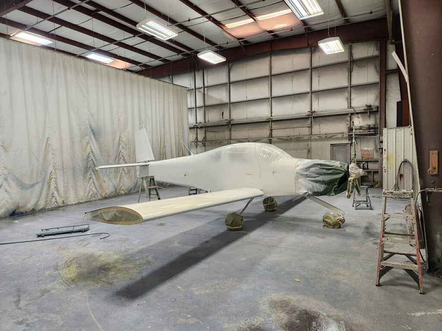
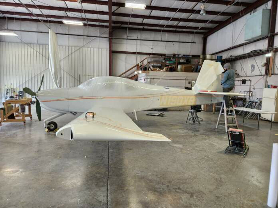
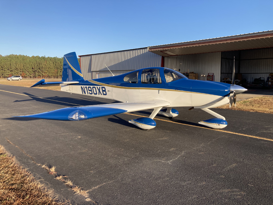
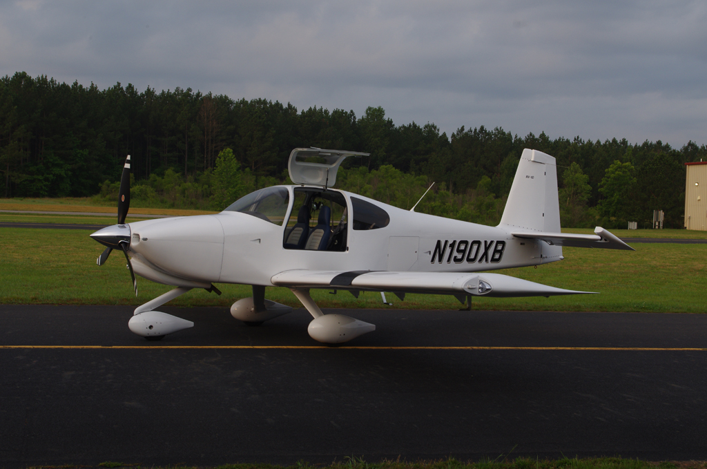
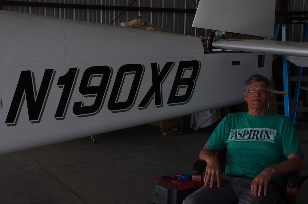
The airplane has been flying about 8 months with over 90 hours accumulated during the Phase 2 period. My scheduled slot has now come due, so N190XB was off to the shop for final painting to include Sapphire Blue upper section and Pharoahs Gold accent striping.
 Chemical Strip
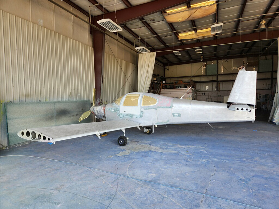 Metal prep and alodine application…
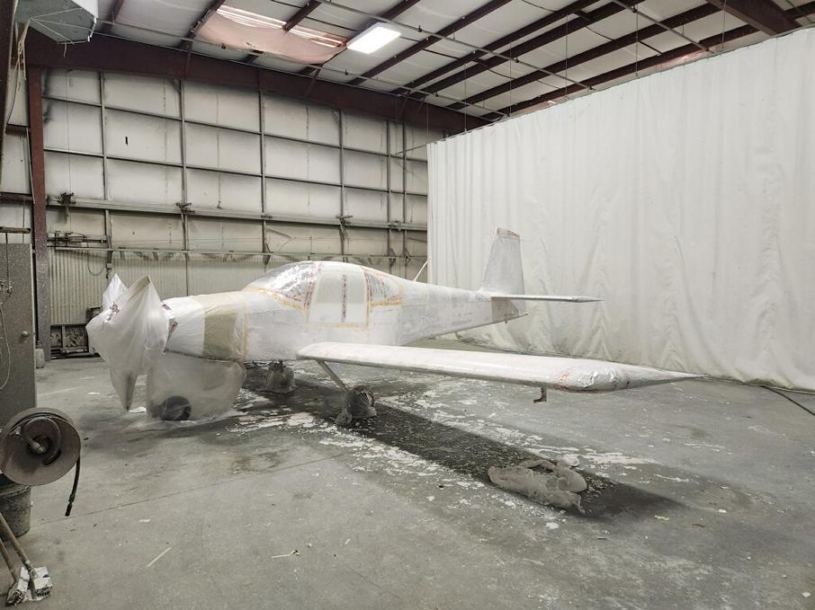
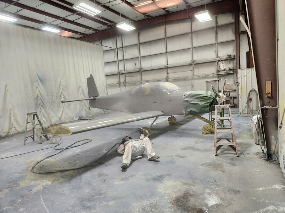 PPG primer applied…
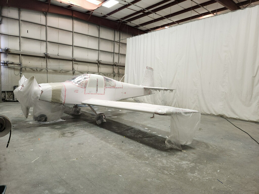
 Base coat of PPG Snow White applied…
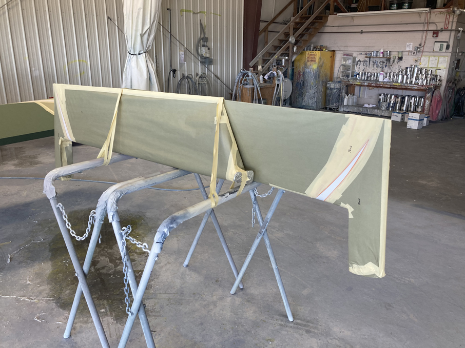
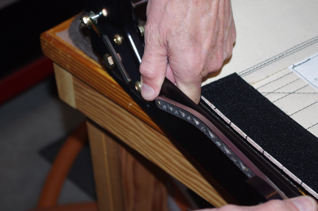
 Elevator and wingtip masking stripe layouts…
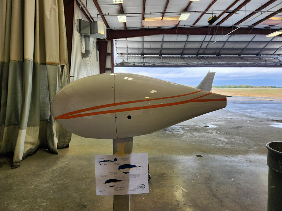
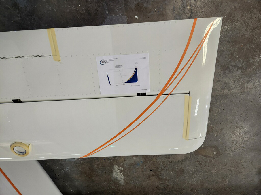
 Wheel pant and fuselage masking stripe layouts…
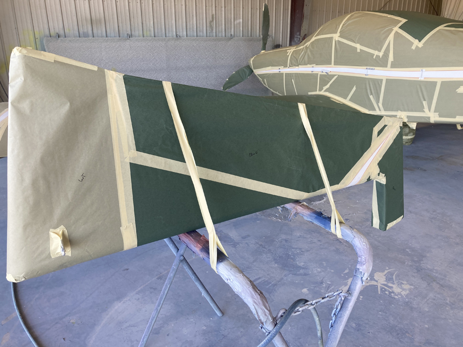
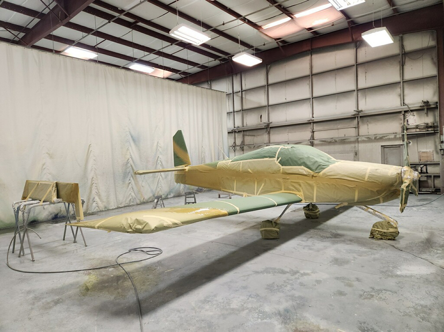
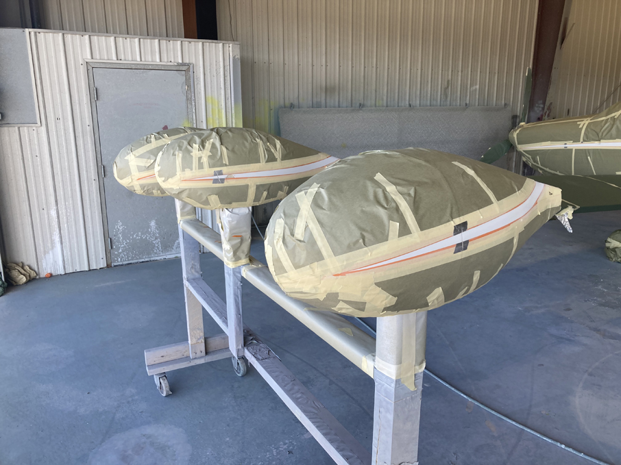 Rudder, elevators and pants masks for gold accent application…
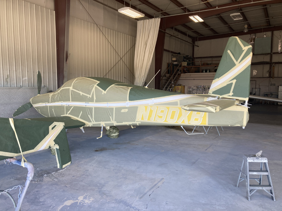
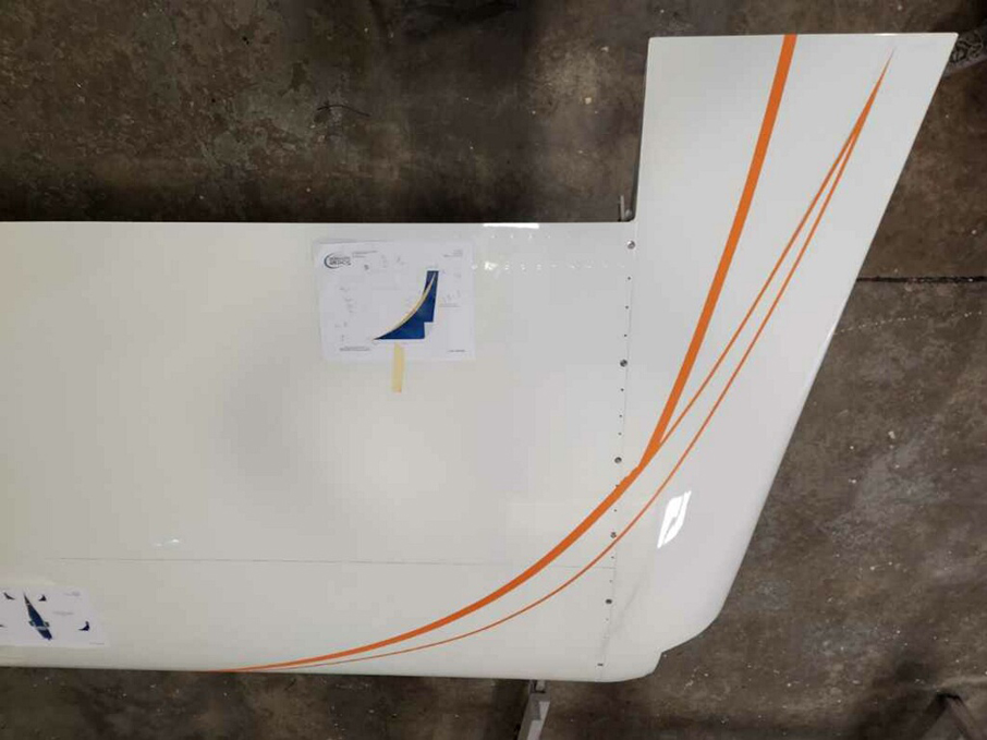
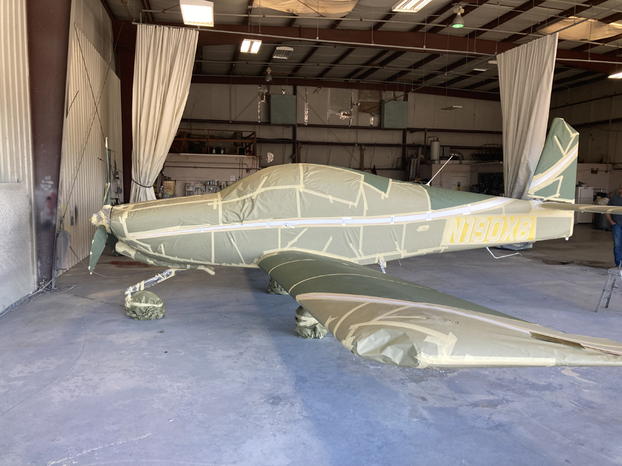 Fuselage masked for gold accent stripe application…
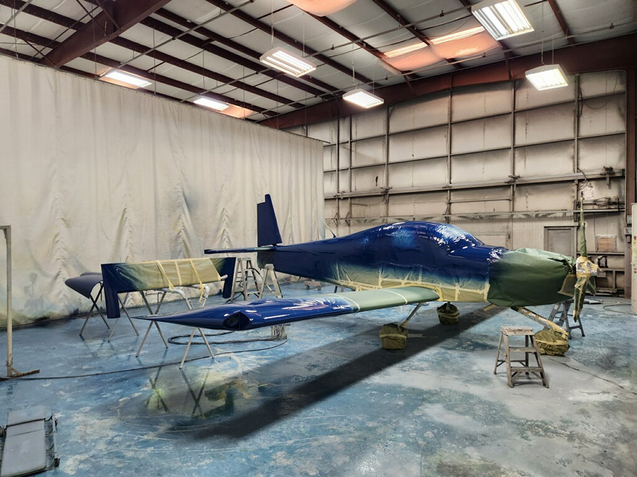 After gold accents, then upper fuselage blue…
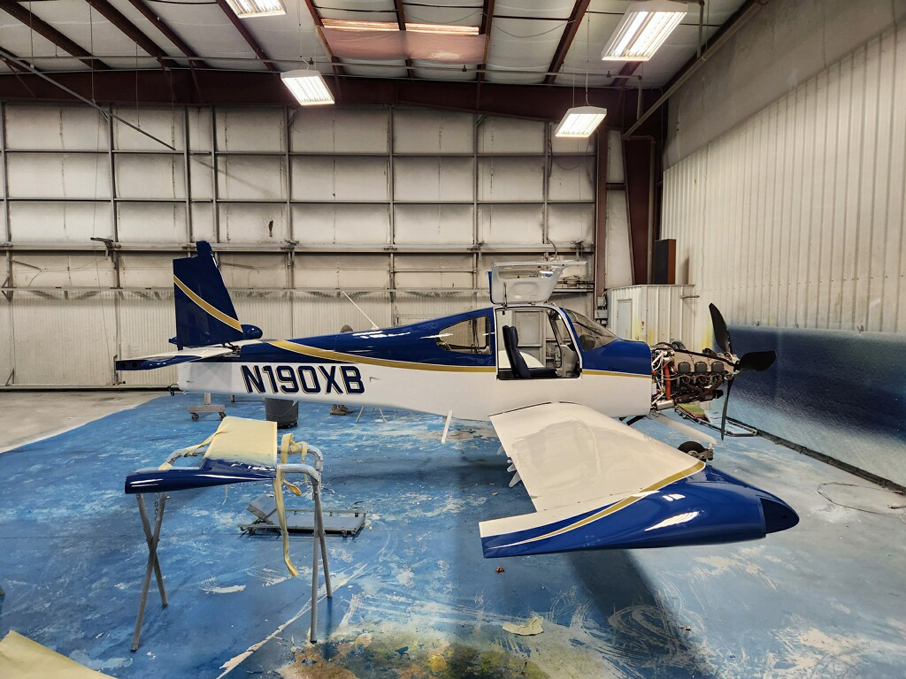 Initial reveal after masks removed…
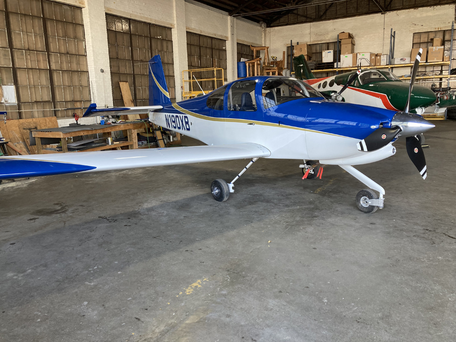 After control surfaces installed. The plane was then ferried back to home base for installation of the wheels pants.
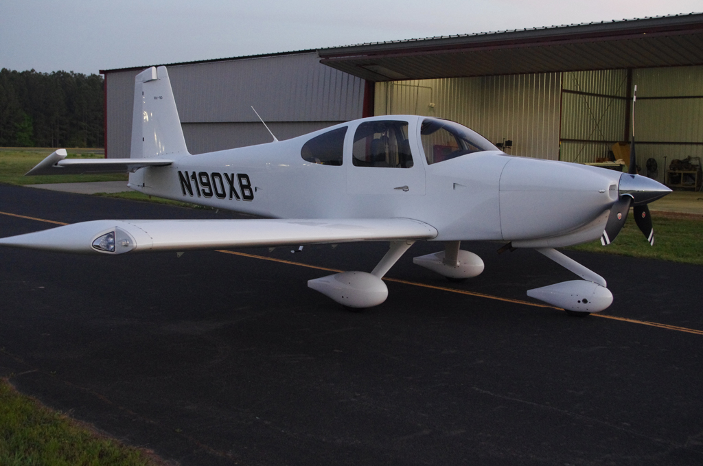
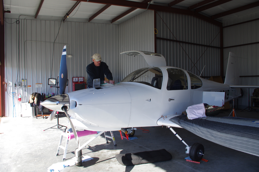
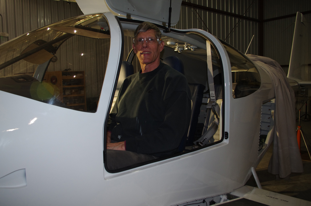
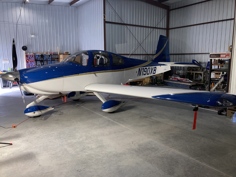 Assembly complete, ready for the next flights…
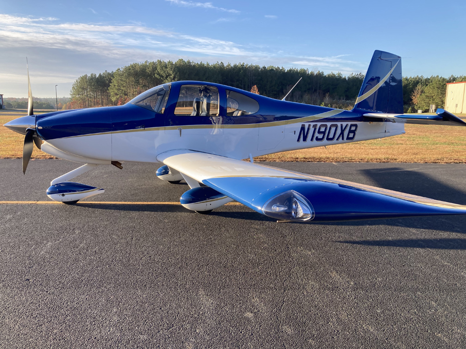
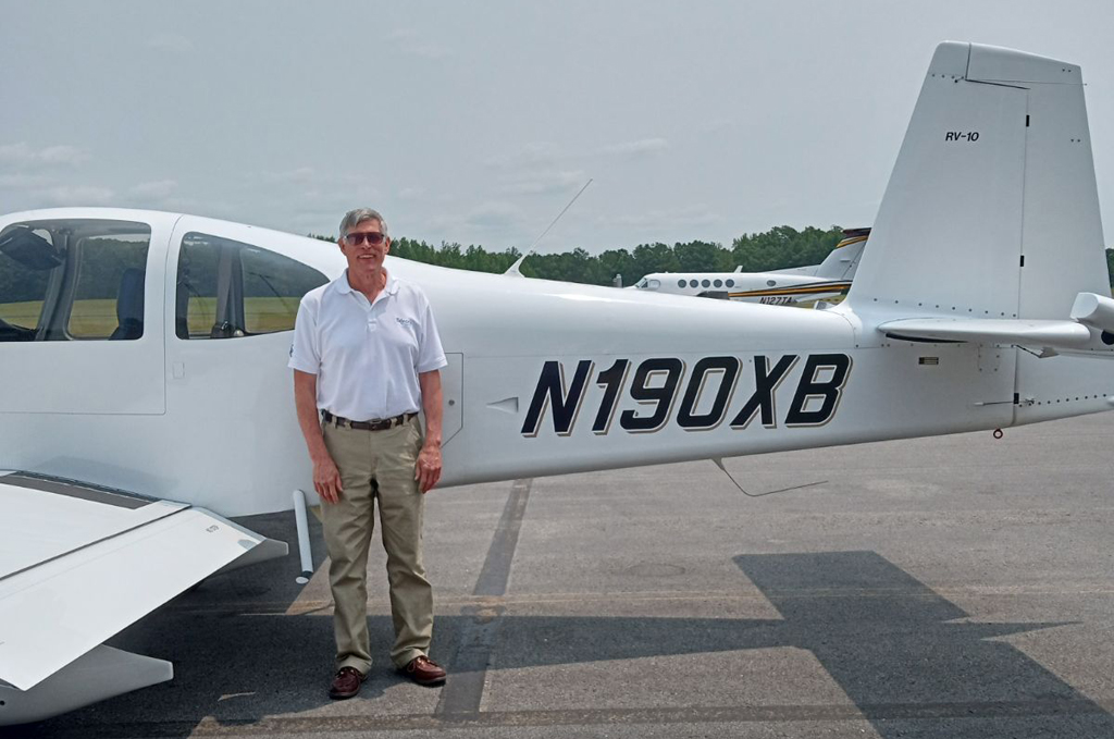
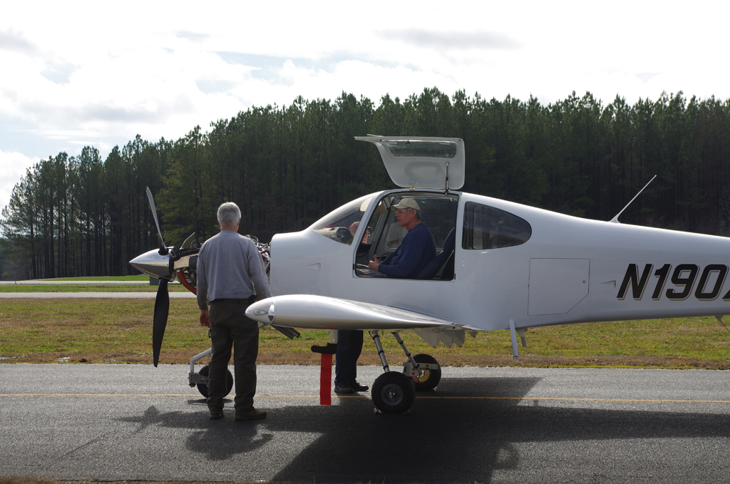
 The day following final assembly was beautiful, just perfect to refresh my instrument rating to get current again. Now the real flying can begin in earnest.
MISC
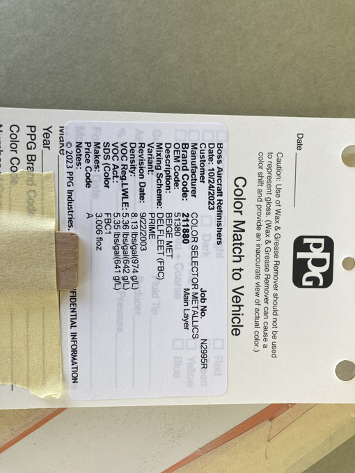
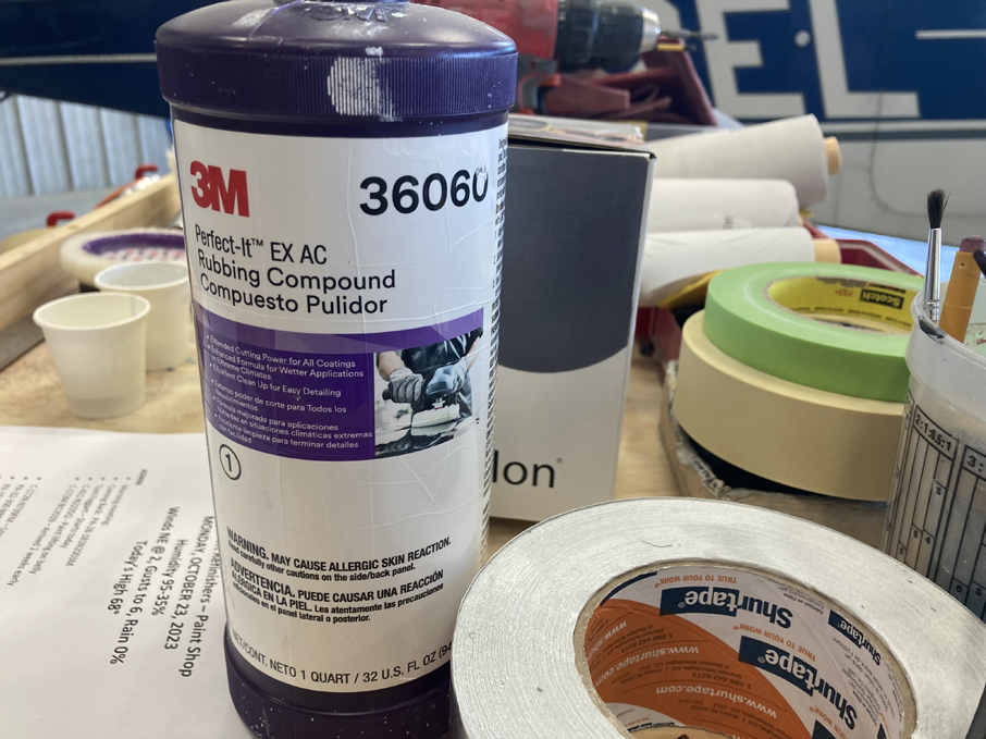 Color match card and 3M buffing compound (for windshield cleanup and repair).
Phase 2
The initial focus of Phase 2 has been short cross-country flights of about an hour for additional practice at ATC communications, enroute navigation, landings under various flap conditions, and final adjustment of avionics settings. It is amazing the number of configurations available on a G3X Touch system. It has taken some time to get comfortable with all the complexity and initial information overload. While still learning the systems every day, my confidence in concluding safe flight has increased.
 I have recently started the ‘$100 hamburger lunch’ flights, which includes meeting colleagues at airports with on-field restaurants. I have looked forward to this type of flight for many years. Next step in expansion of my flying horizons will be refresh my instrument skills and get current again with an Instrument Proficiency Check (IPC). Then longer trips may be forthcoming.
Phase 1
The Phase 1 period began immediately after receipt of the Airworthiness Certificate. First flight occurred on March 15, 2023. Many thanks to Tal for his support during the fly-off period. Could not have done it without him.
 Because of the hot weather in this part of the country, many of the initial flights occurred around sunrise in the morning. This was beneficial to get cooler air for engine break-in, better lift, and pilot comfort. It also helped avoid local traffic, as most activity started later in the morning.
The 40 hour milestone was reached on May 3, 2023. I utilized the EAA Flight Test Manual as the basis for establishing the flight characteristics of the aircraft. The test cards were completed on June 16, 2023 with 57.3 hours on the engine. There were no major issues to resolve during this period.
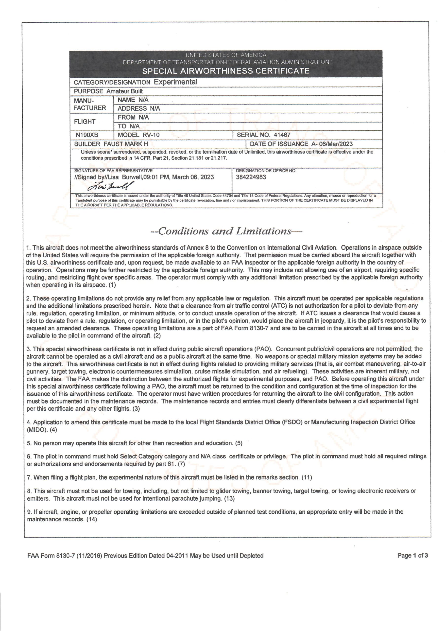
Airworthiness Certificate
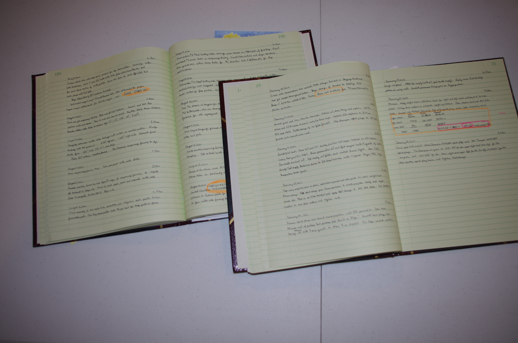
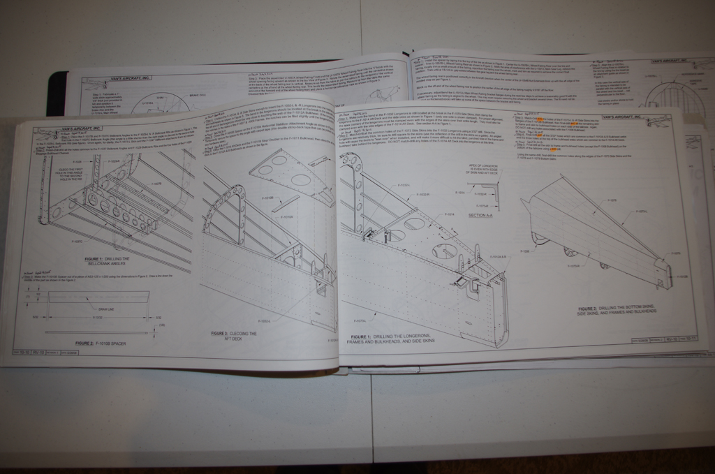
The day has finally arrived for the DAR to inspect the airplane. All my logbooks, build plans, photos and other documentation were laid out for review. There were no paperwork issues, but a few minor items to address on the airplane. Overall a successful inspection!
Certificate issued on March 6, 2023 for N190XB!
First Engine Start
Here is a brief video of the first engine start from January 30, 2023. This was an exciting day and a huge milestone in the project. The engine started right away and everything ran great. Looking forward soon to the airworthiness inspection and first flight!
Click this link to see the video: N190XB-FirstStart-2023-0130v1
Many thanks to Terry, Mark, and especially Tal for their unwavering support helping to make this project happen.
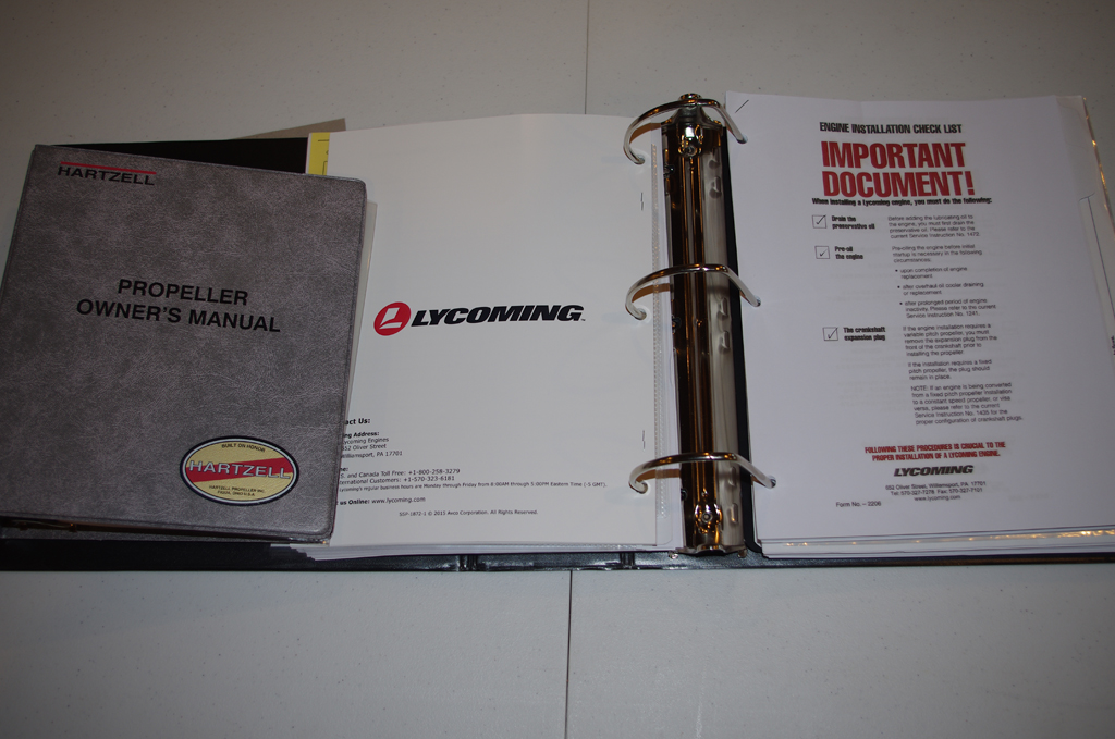
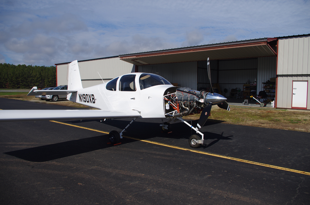
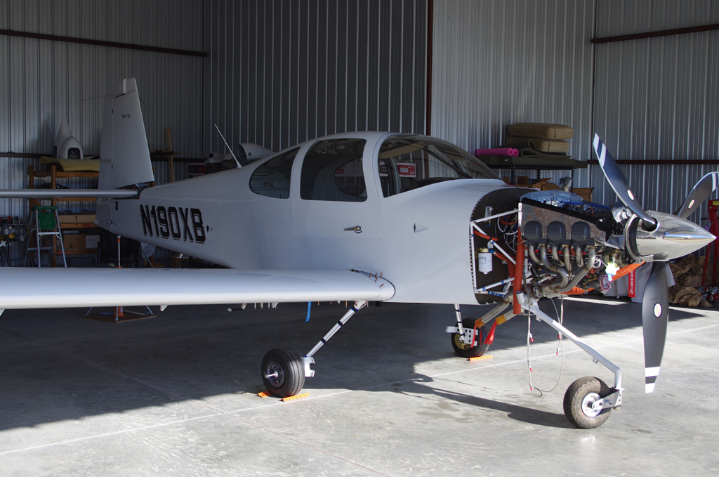
Engine, Propeller and Final Preparations
The final installations have begun after many years of component fabrication.
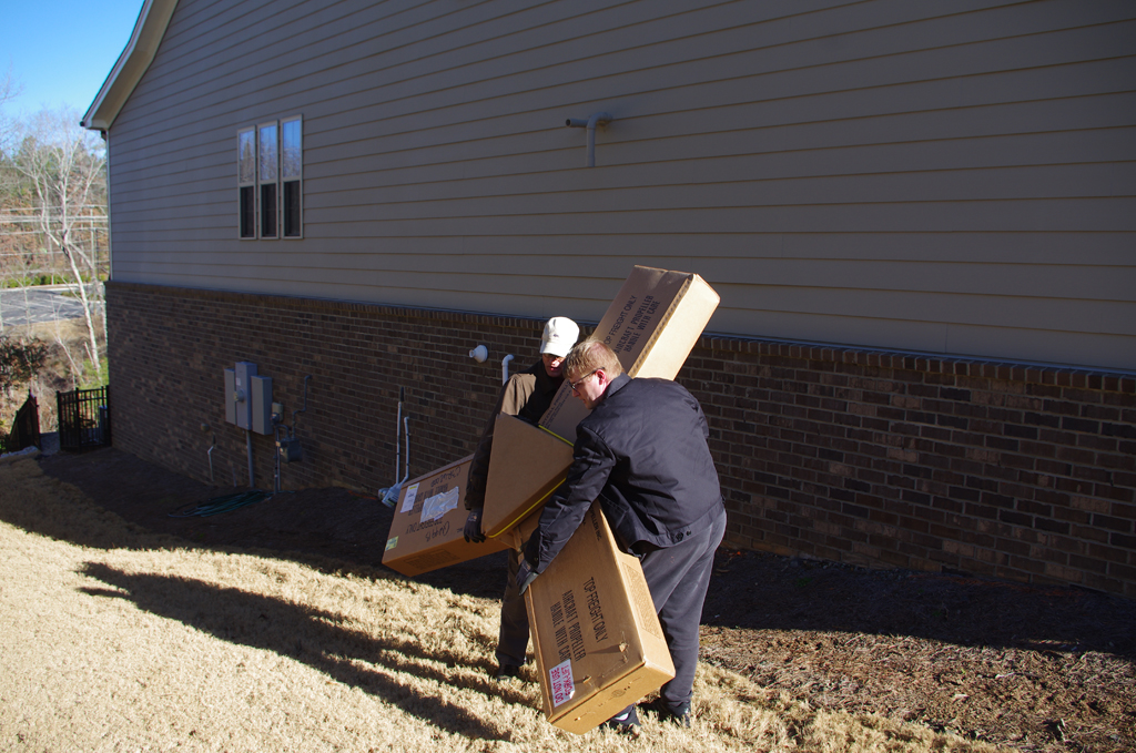
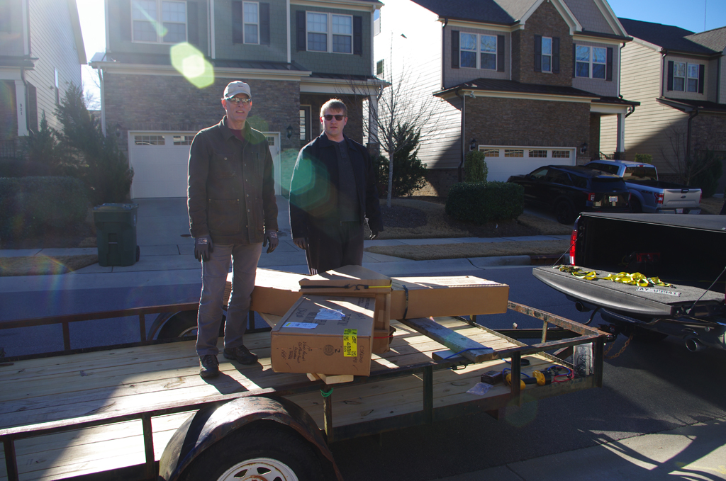 My son and I carried the propeller out of basement storage for transport to the airport.
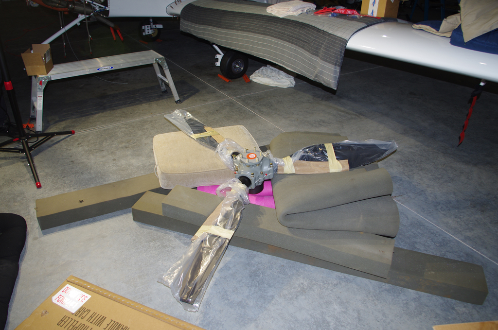
 The unwrapped propeller on the floor was checked, then hung by Terry, Eric and I. Sorry no photos were taken during that process. Needless to say, everything went well and the prop looks great. Easily the best looking thing about the aircraft!
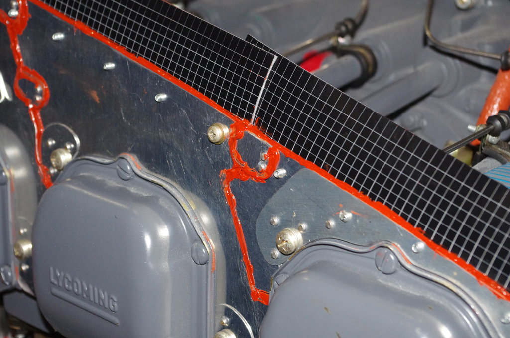
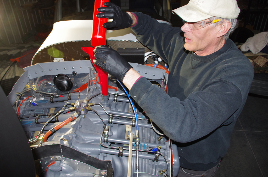 High temperature RTV was applied to gaps in the baffling and between cylinder heads. The engine was then filled with 12qts of Aeroshell 100 mineral oil, which will be used for the 25-30hour engine break-in period.
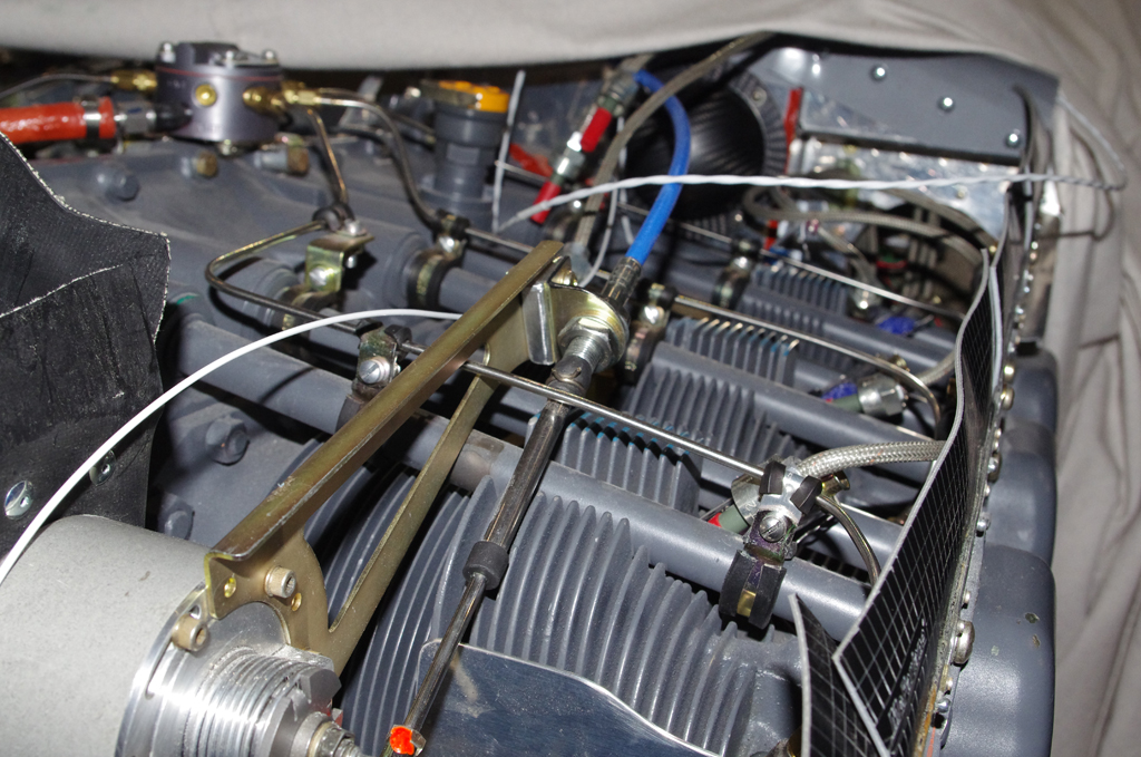
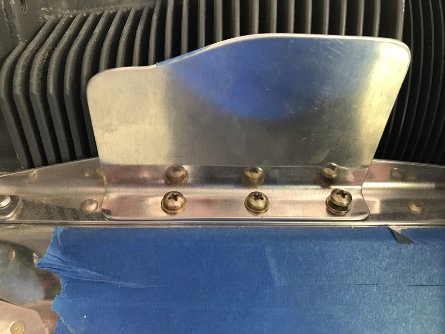 Final connections of the propeller governor cable and bracket adjustments were made. The air dams with their original heights were installed. These were later reduced in size after some initial flight tests were performed.
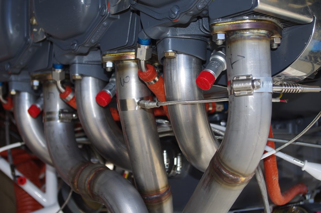
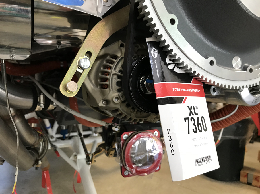 EGT probes were installed in the exhaust manifold, then bundled with their corresponding CHT probe wires. The alternator belt was tensioned and Safe-T-Wired secure.
 Measuring the leading edge of the wing provided a reference point for the CG calculations.
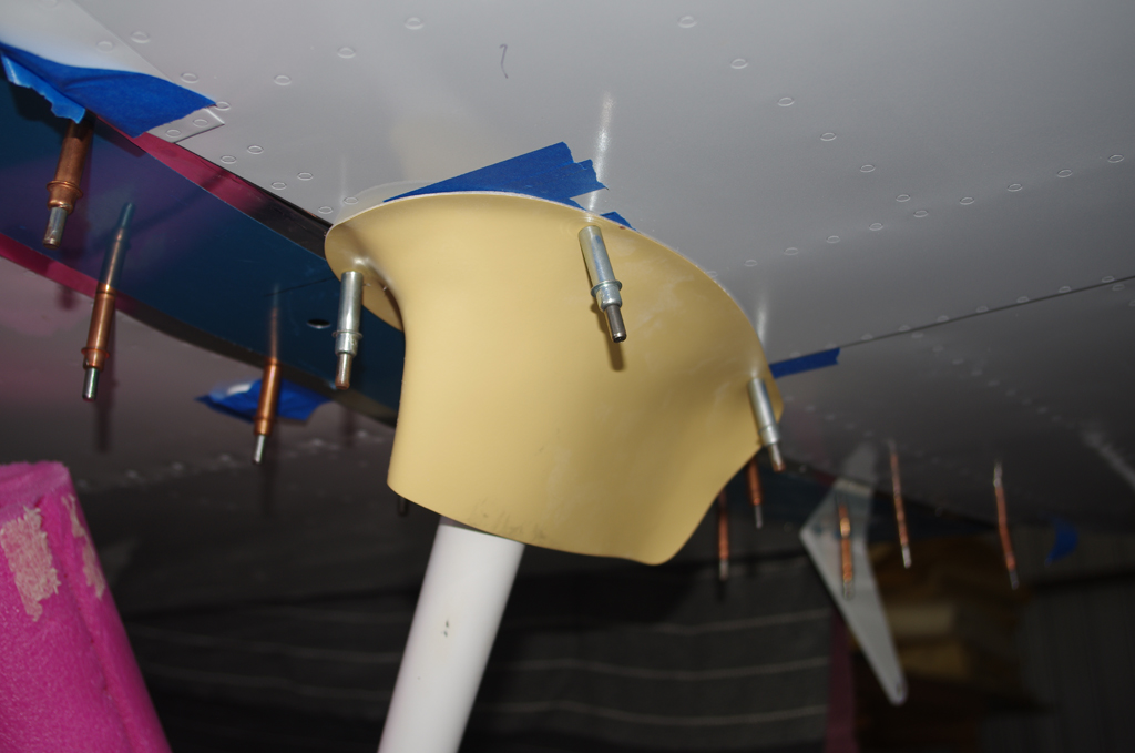
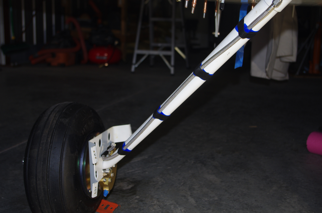 Intersection fairings for the gear legs were initially fit, then later painted and installed after the TS Flightlines stainless braided brake lines.
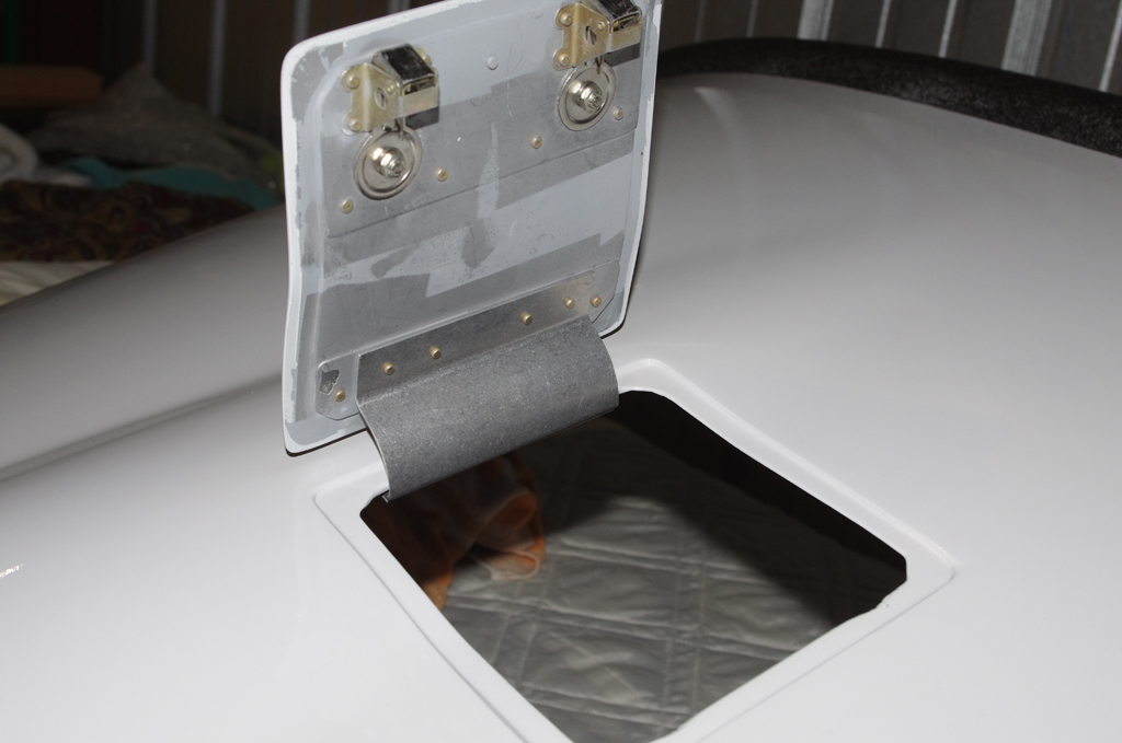
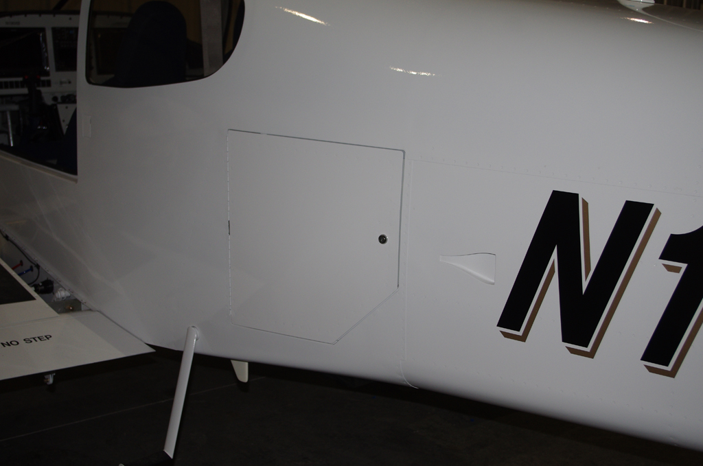
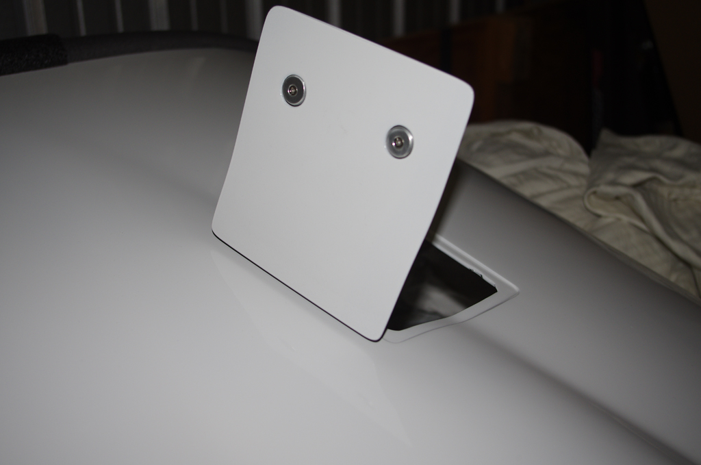 Final installation of the oil door with hidden hinge…
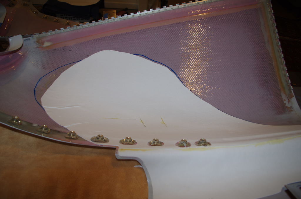
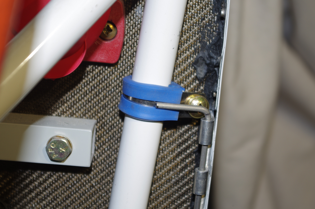 A 1/16″ ceramic mat was contact cemented in the lower cowl, then covered with Vans aluminum heat shielding. This combination should prevent the cowl paint from being scorched by the exhaust manifold heat. Lower cowl pins will be secured against these Adel clamps with tie wraps.
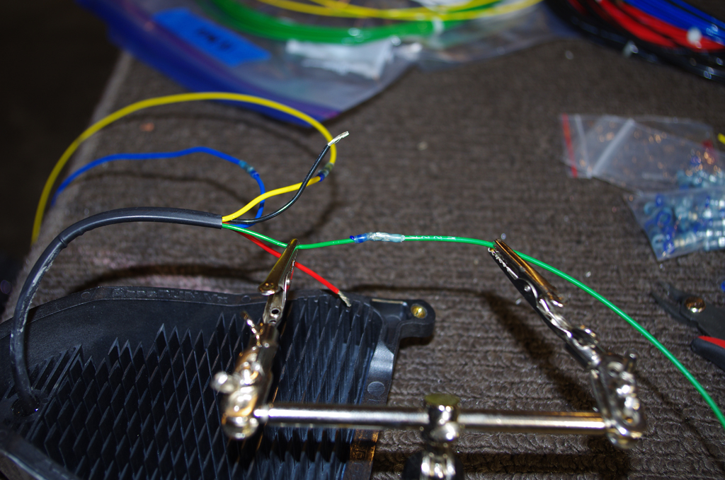
 Final wiring for AeroLED VX landing lights were Solder Sealed, then run through conduit to the wingtips.
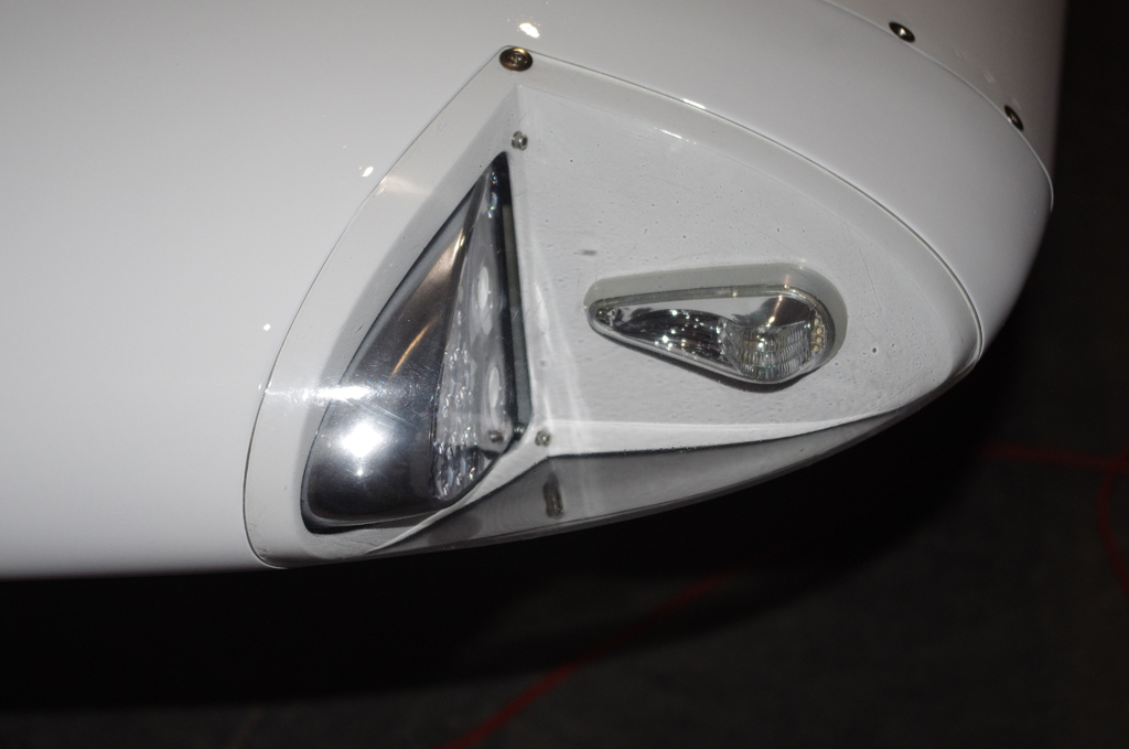
 AeroLED VX landing and NS position lights/strobes…
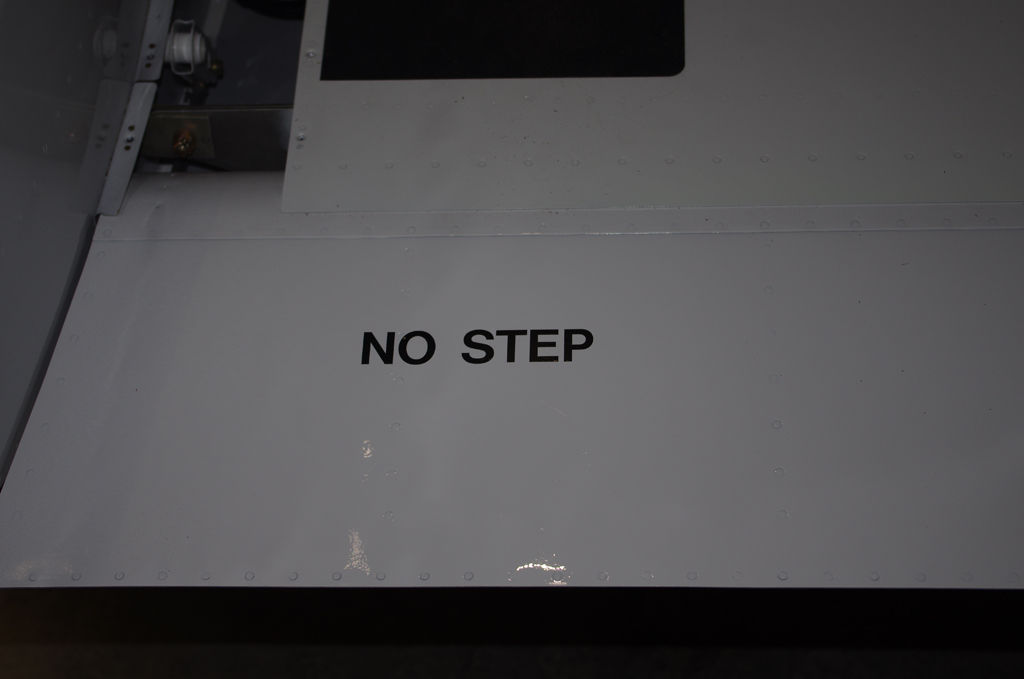
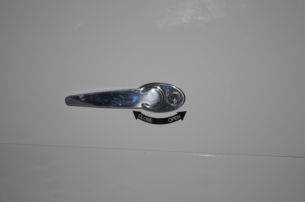 Decals applied to flaps and doors…
 Wiring from control sticks to system buses used DB15 connections for easy maintenance or removal.
 Ground wires were covered in thick rubber fuel lines to prevent chaffing, then seat pans were installed.
 Aerosport auxiliary seat handles were installed for easier operation. Then final inspection and review of everything to date.
All that’s left before first engine start is sit back and wait for good weather outside. It certainly has been a long time coming. Very excited about this next major milestone.
Walk Around (1)
Here is a walk-around of progress made in the last few weeks. These shows the left side review, which essentially mirrors the right side components.
Right Side
Left Side
Data Plate
Last week the data plate was installed on the left rear fuselage under the horizontal stabilizer. Together with the FAA registration I understand this combination means I have a real airplane!
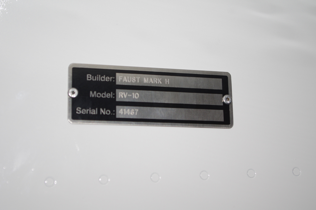
I selected the simplest data plate possible: Builder, model and serial number.
VS Attach and Misc.
Much of the finalized assembly was not photographed in-progress, as fabrication of the parts was generally covered in previous posts. Plus I really wanted to get done without taking further time on the website. A greater reliance on video content was made as the build headed for completion.
VERTICAL STABILIZER
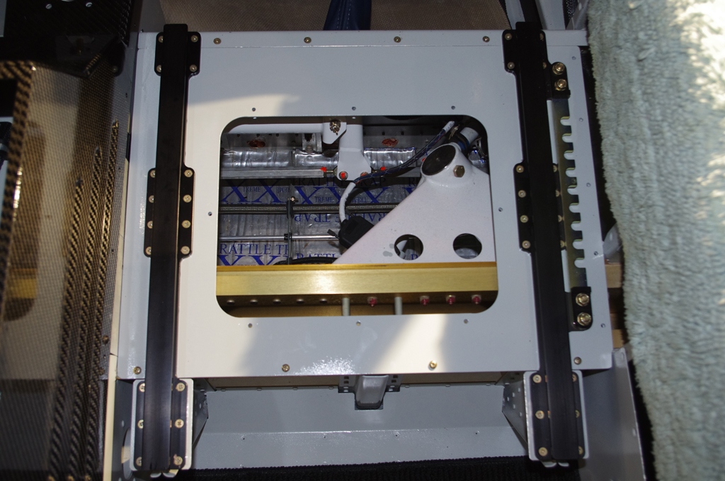
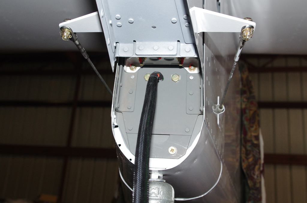
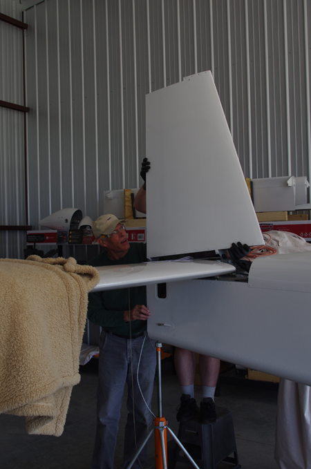 Here the vertical stabilizer was being attached to the empennage – hopefully for the last time.
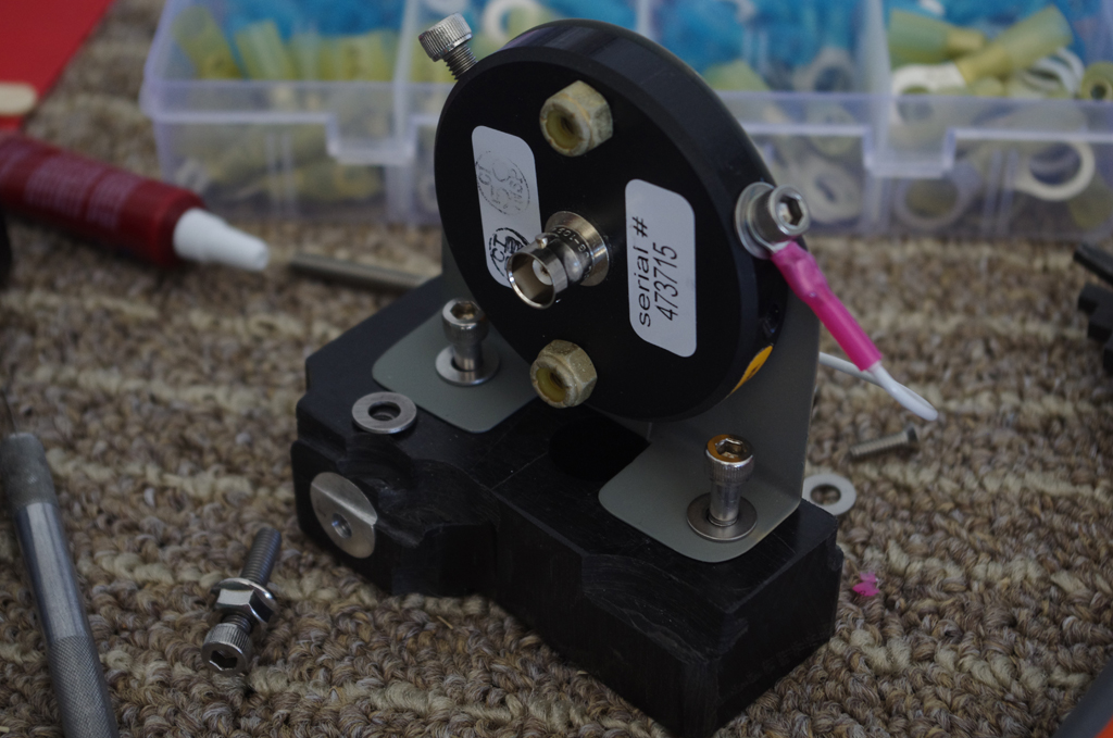
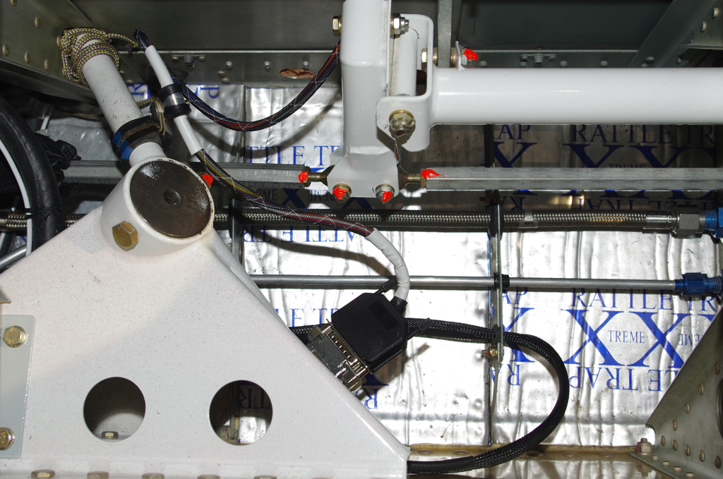
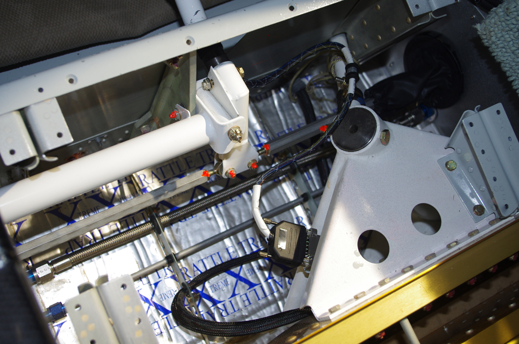
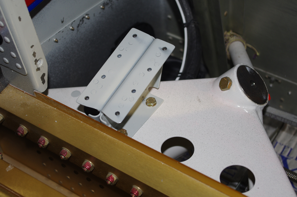
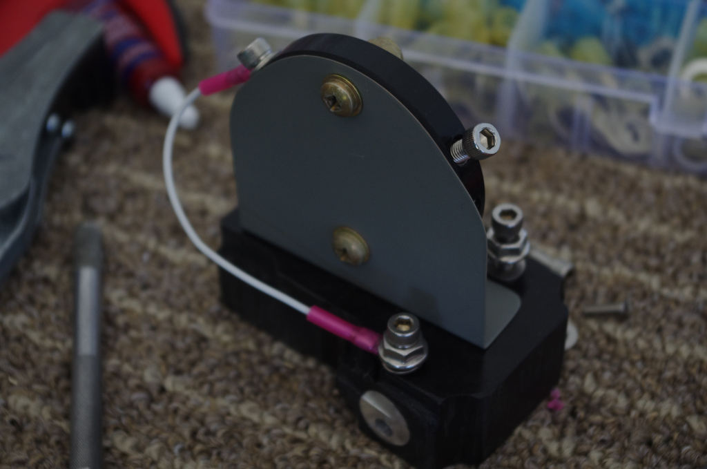 I made this custom NAV antenna bracket many moons ago. In retrospect, I would probably forgo this bracket and mount the antenna directly under the fuselage.
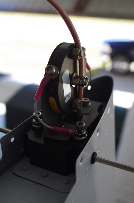
 Anyway – here was the final connection and covering by the VS cap.
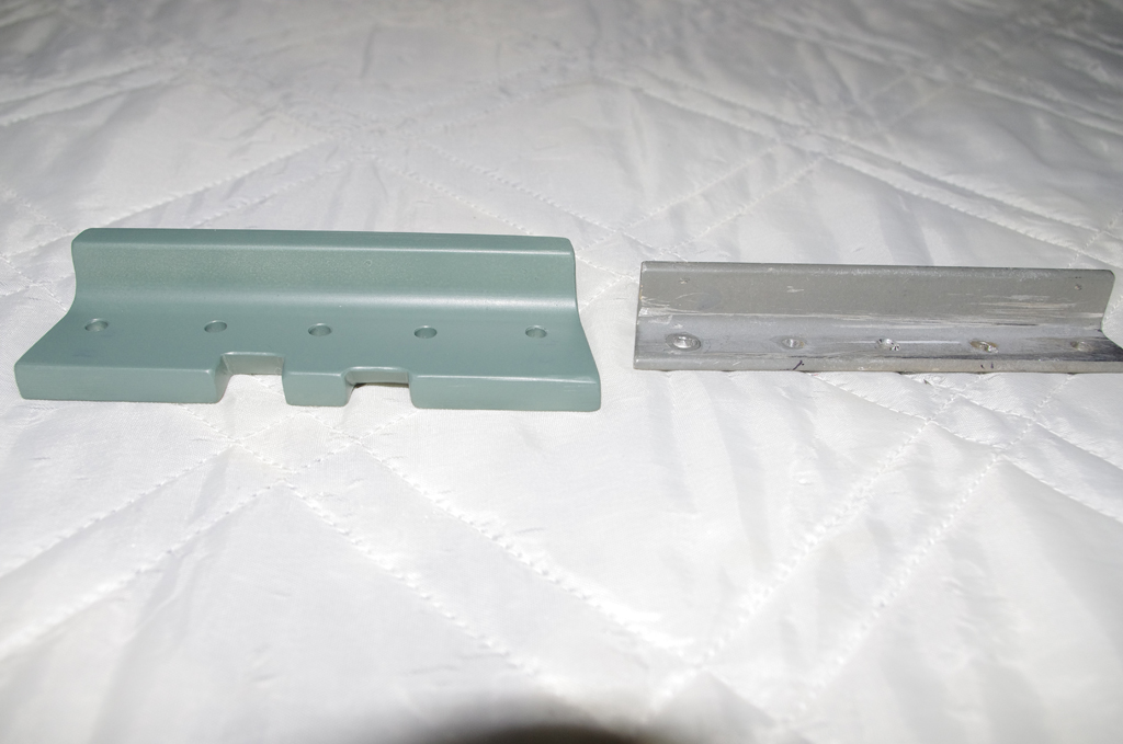 The left photo shows the Suntail Strobe/Nav wiring exit between the rear fuselage and the rudder bottom. On the right is the original elevator stop replaced with a much heavier and larger alternate means to comply with Service Bulletin SB18-03-30 from Vans. This modification prevents over-rotation of UP elevator.
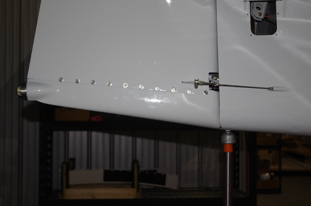
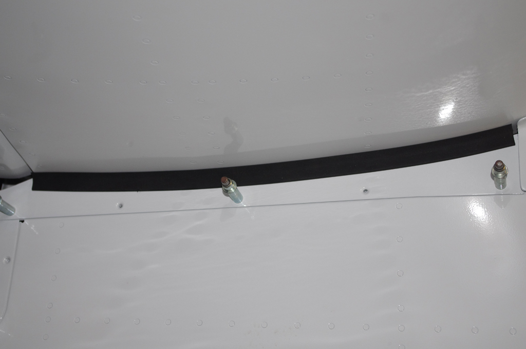 Following attachment of the rudder bottom, intersection fairings around the VS and HS were installed. Thin rubber edging protects the HS paint from the elevator trim covering. Note the elevator horn to elevator push rod assembly in the upper right of the first photo.
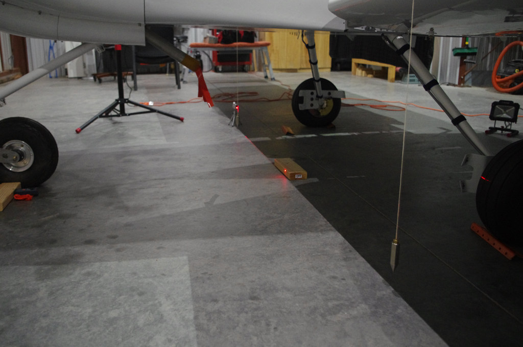
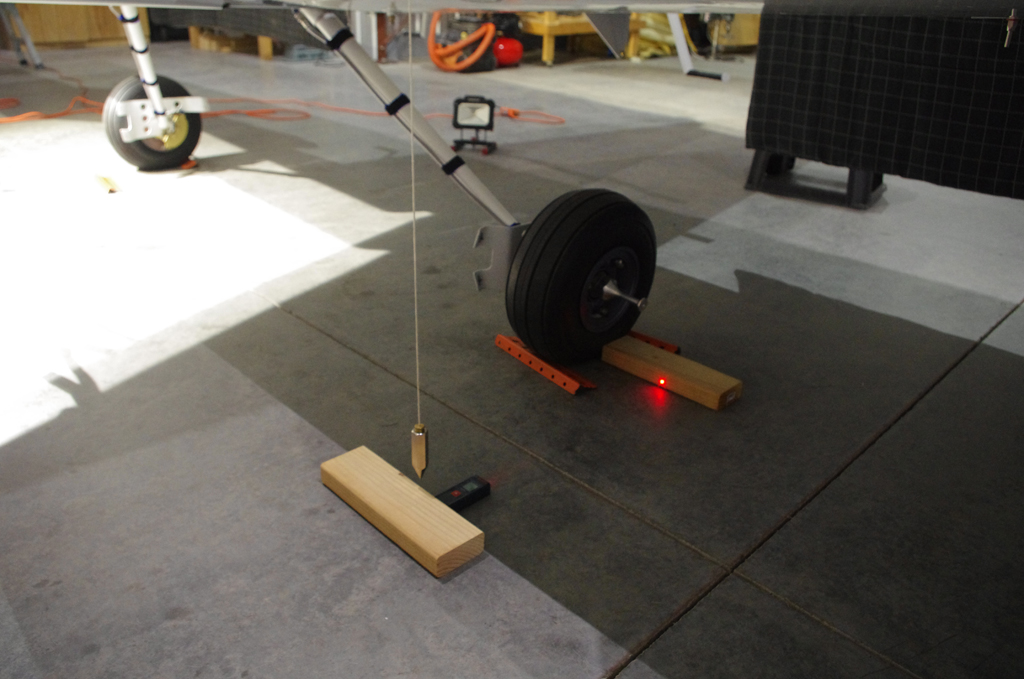
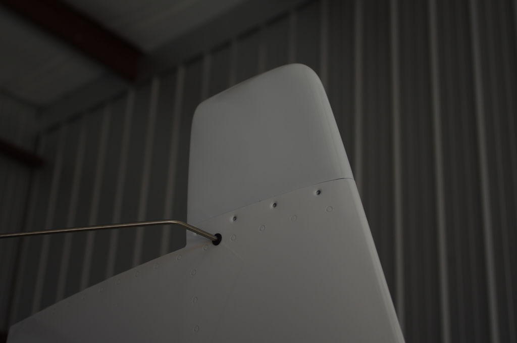
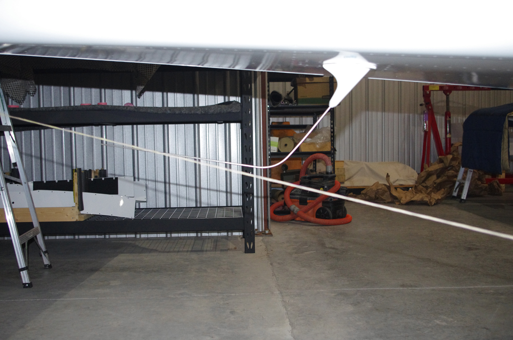 This photo shows a taut line extending from the main wheels at ground level to the rear tie down point. This confirms the COM1 antenna will not scrape on the runway during takeoffs or landings.
BATTERY BOXES
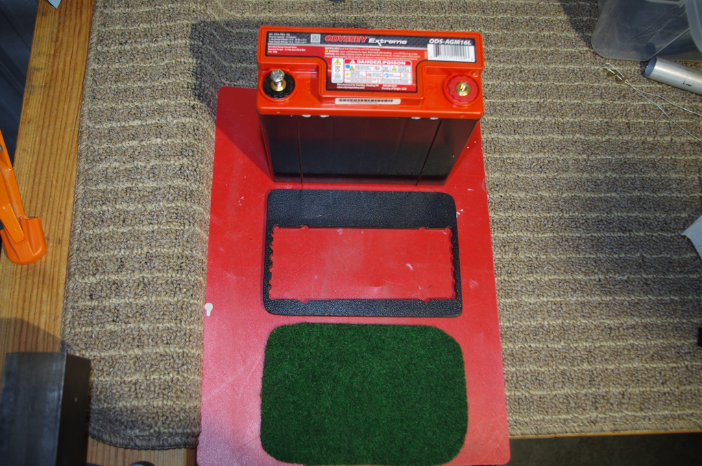
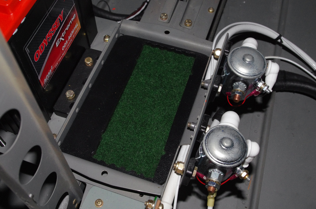 The Odessey 680 batteries were secured with a Delrin-like polymer frame with a felt underlayment for protection. Here are the components before assembly.
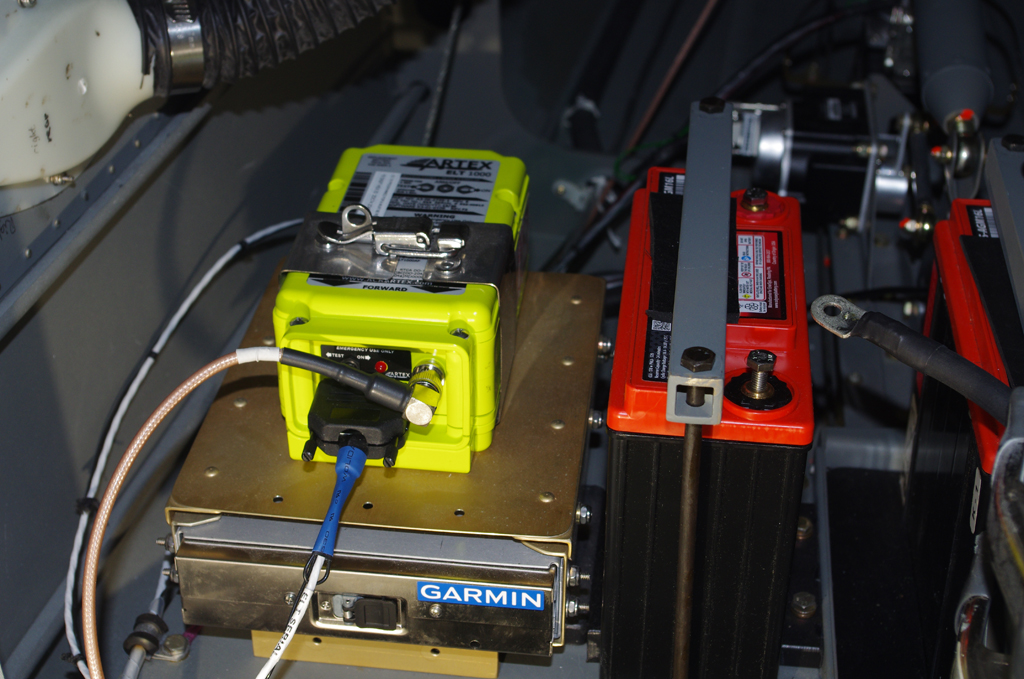
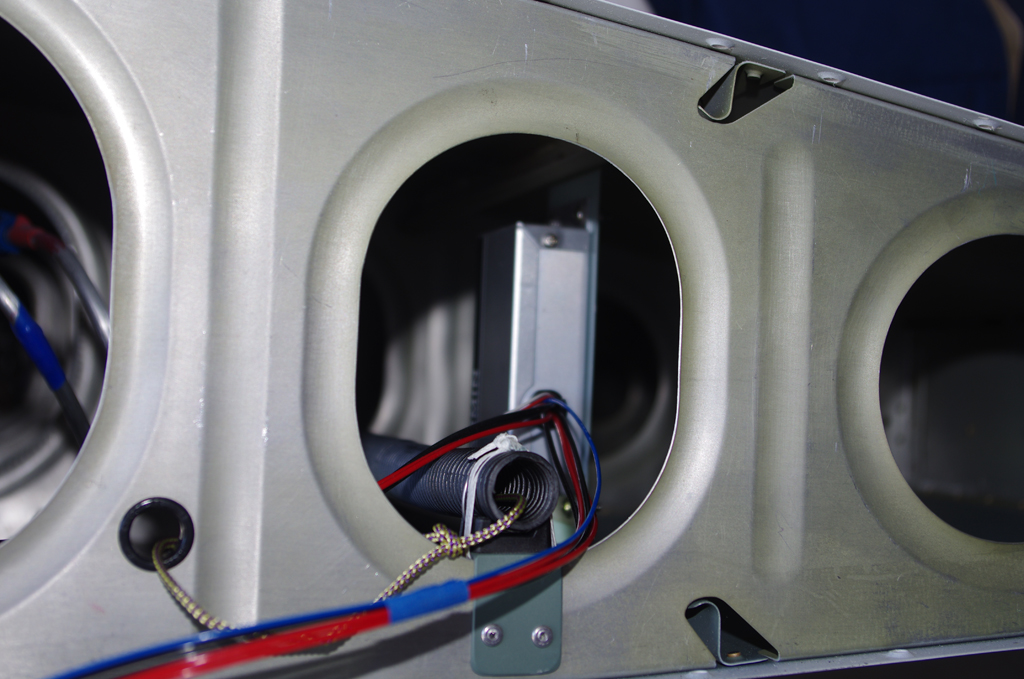
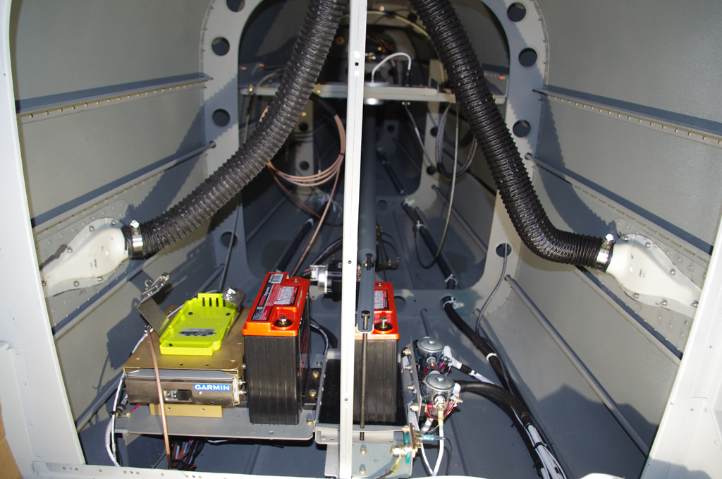 The final configurations of the battery boxes, Artex 1000 ELT, and the Garmin GTX45R transponder/ADSB behind the baggage bulkhead is show here.