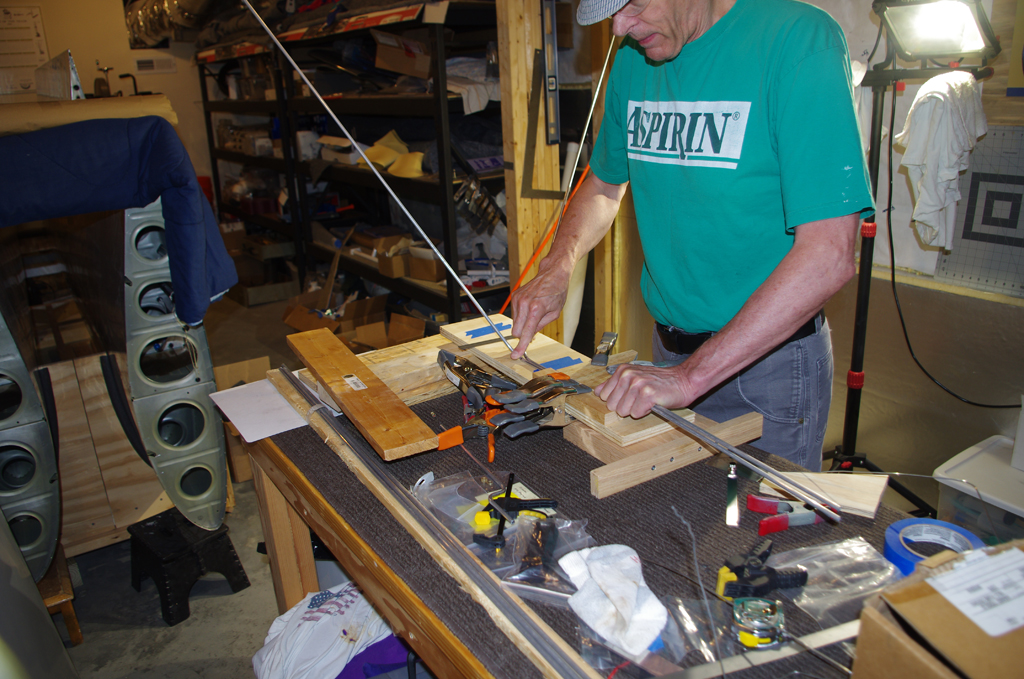
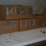
The continuation from the brake line fabrication is preparation of the rudder pedal system.
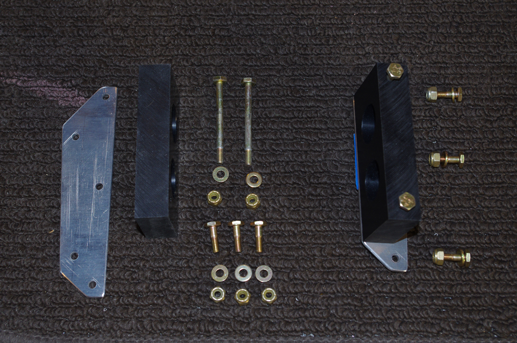
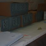
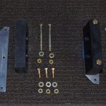 The bearing blocks and mount plate were laid out with the corresponding hardware ready for processing. The blocks appear to be black Delrin (or equivalent).
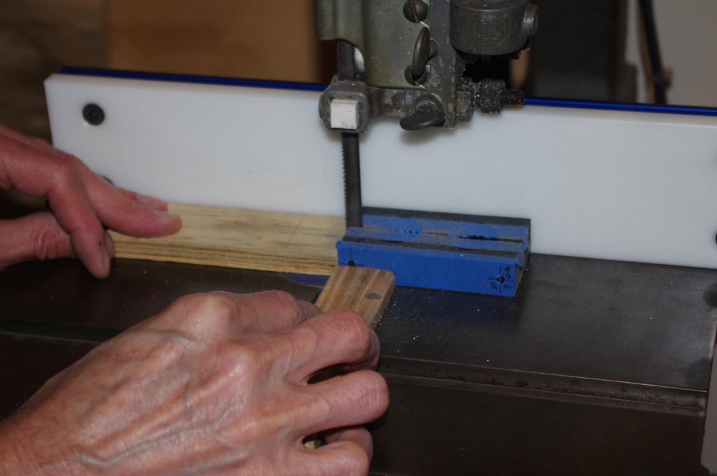
 The center bearing block was measured, then drilled with a #10 drill to accept AN3-22A bolts. The block was then cut in half for later mounting to the rudder pedal brace.
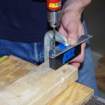
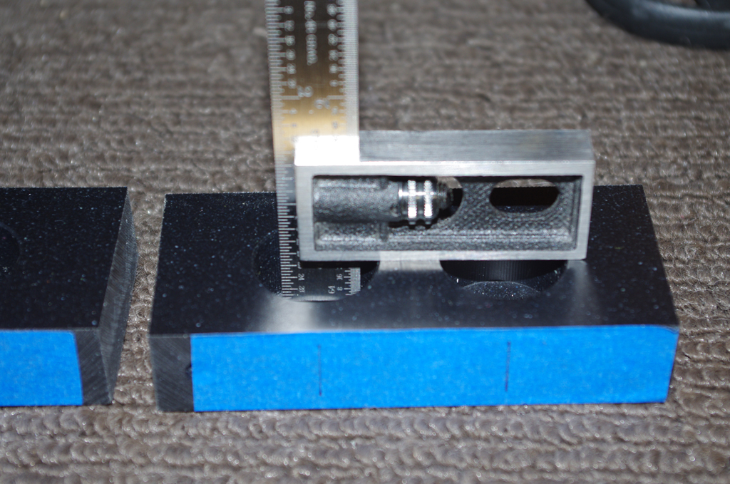
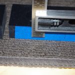
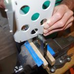
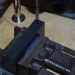 The side bearing blocks were drilled about 1/8″ deep using the mount plates as a template. The remainder of the hole was completed in the drill press to achieve perpendicular alignment.
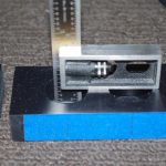
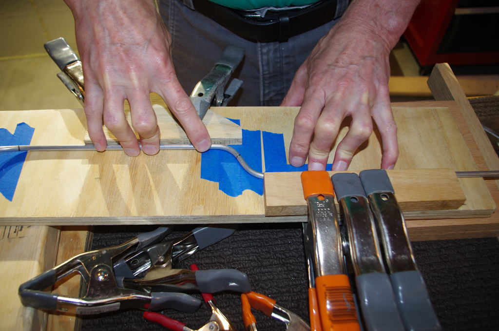
 A feature recommended by other builders for the side bearing were oil holes added to the bearing blocks. These facilitate lubricating the friction points after installation. The depth and location are first checked before going to the drill press.
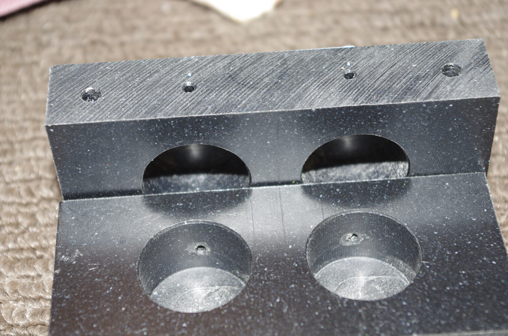
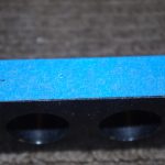
 This photo shows the completed bearing blocks after addition of the oil holes. Deburring the Delrin on the inside of the bearing hole required the use of a Dremel tool.
 Spacers for the lower brake cylinder attachment point were made from AT6-058×5/16 tube. These are sized to accommodate AN3-12 bolts.
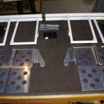
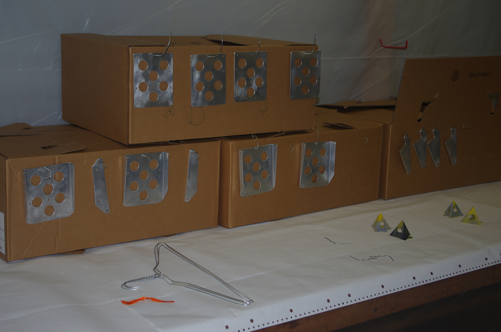
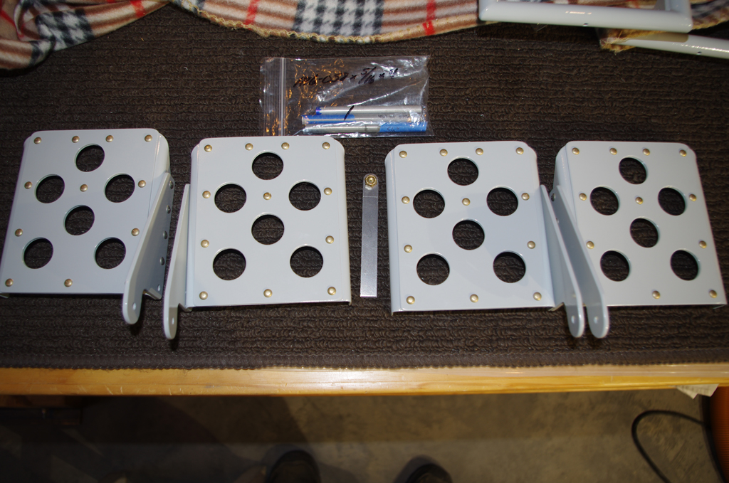
 The main pedal parts were staged for match drilling and preparation for priming (SEM Self-Etch Primer) and final paint (PPG Concept – Boeing Grey).
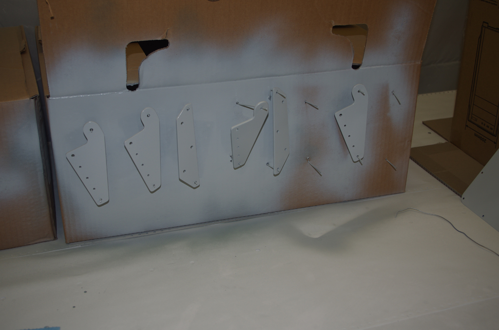
 Parts staged, primed and painted.
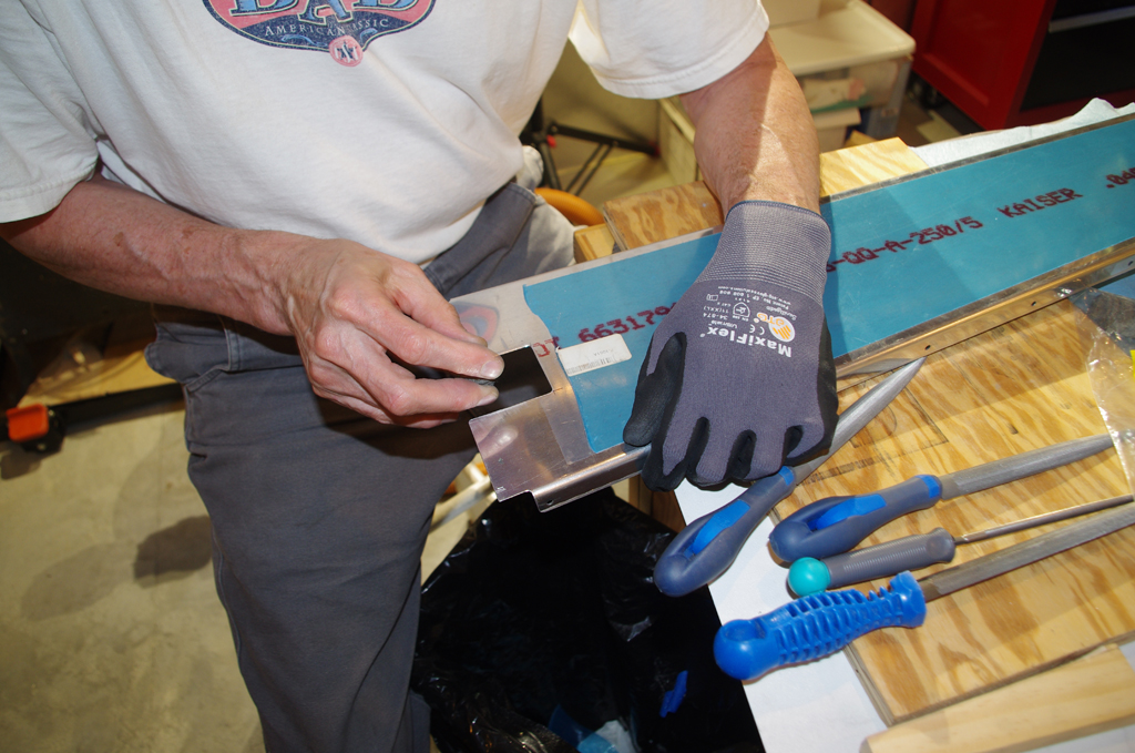
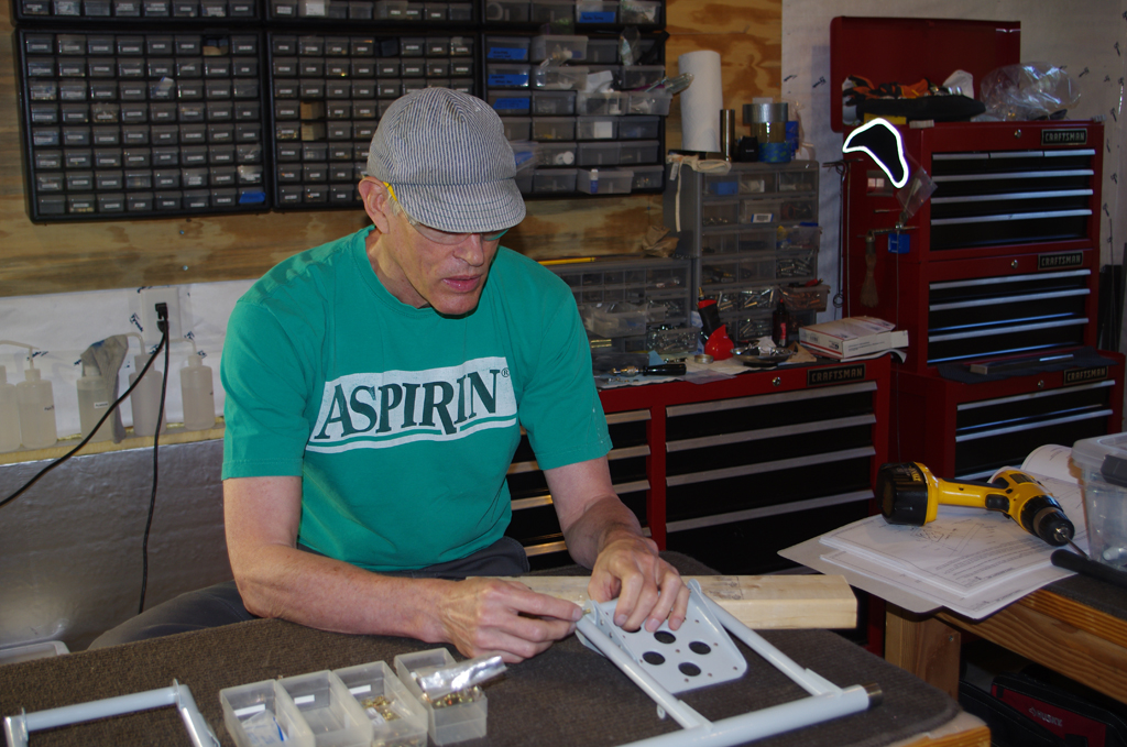
 The brake doubler plates and brake pedal side plates were riveted together to make the brake pedal subassemblies.
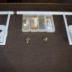
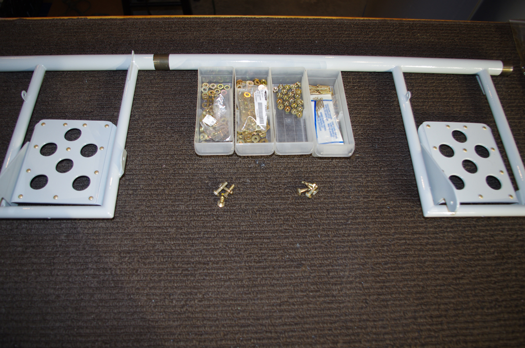
 All the prepared parts and hardware were stage for attachment to the pedal levers.
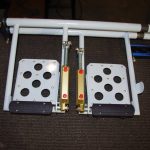
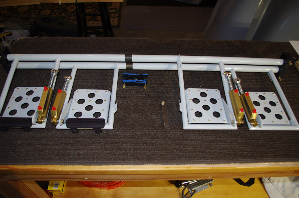
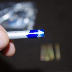
 The Vans kit uses Matco brake components. Here the completed pedals are enhanced with AeroSport pedal extensions 3D imprinted with N190XB. Next actions are to fit these units into the fuselage, then attach soft brake lines.
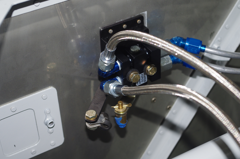
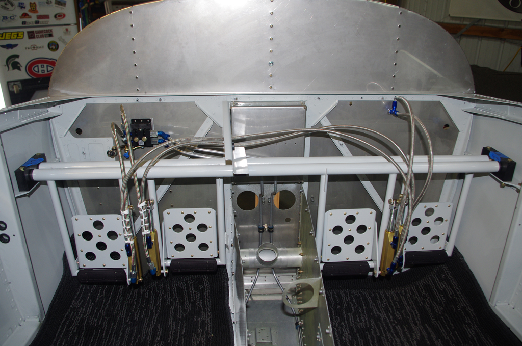
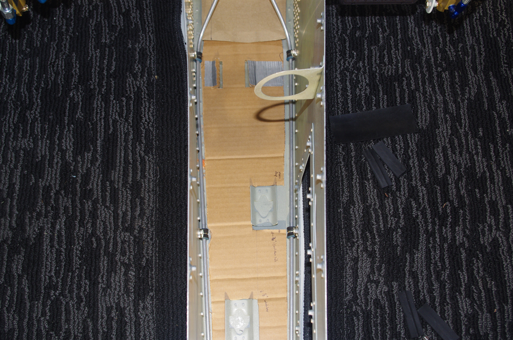
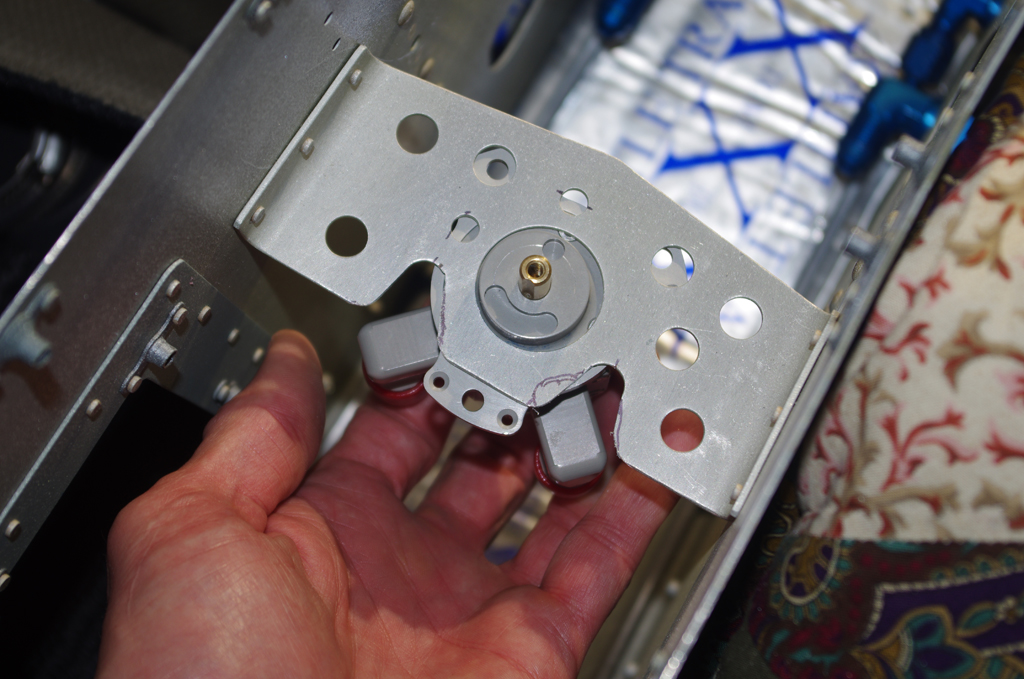
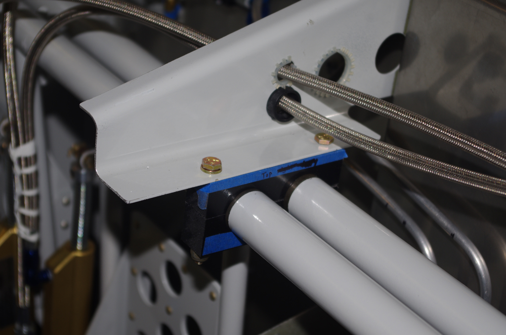 The parking brake connected with heavy duty stainless lines to the master cylinders on the pilot’s pedals. The Bonaco coated, flexible lines were then run through the center lever bracket to the copilot side.
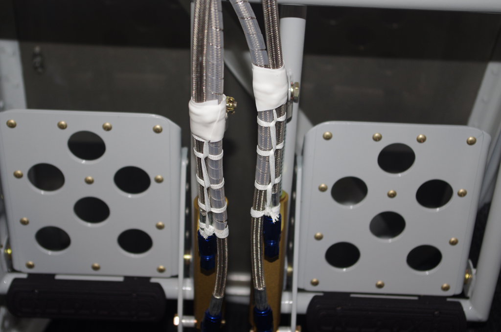
 Here are details about the cable lace and rescue tape applied to hold the lines in place.
 In researching the fuel level sensors, many recommendations were made to replace the regular gasket material with Viton. Here are pictures of the McFarlane product to be installed at a later date. In addition, I also ordered Viton Fluoroelastomer O-rings for the #8 screws which hold the fuel sensor base plate onto the wing tanks. These were obtained from McMaster part number 9464K12.