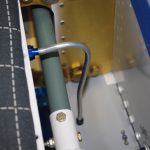
Much of the finalized assembly was not photographed in-progress, as fabrication of the parts was generally covered in previous posts. Plus I really wanted to get done without taking further time on the website. A greater reliance on video content was made as the build headed for completion.
VERTICAL STABILIZER
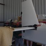 Here the vertical stabilizer was being attached to the empennage – hopefully for the last time.
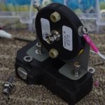
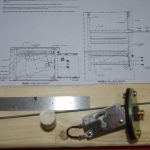
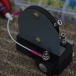 I made this custom NAV antenna bracket many moons ago. In retrospect, I would probably forgo this bracket and mount the antenna directly under the fuselage.
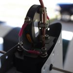
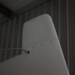 Anyway – here was the final connection and covering by the VS cap.
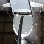
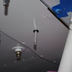
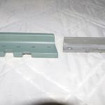 The left photo shows the Suntail Strobe/Nav wiring exit between the rear fuselage and the rudder bottom. On the right is the original elevator stop replaced with a much heavier and larger alternate means to comply with Service Bulletin SB18-03-30 from Vans. This modification prevents over-rotation of UP elevator.
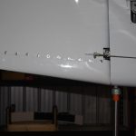
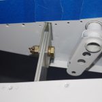
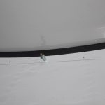 Following attachment of the rudder bottom, intersection fairings around the VS and HS were installed. Thin rubber edging protects the HS paint from the elevator trim covering. Note the elevator horn to elevator push rod assembly in the upper right of the first photo.
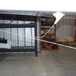 This photo shows a taut line extending from the main wheels at ground level to the rear tie down point. This confirms the COM1 antenna will not scrape on the runway during takeoffs or landings.
BATTERY BOXES
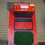
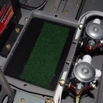 The Odessey 680 batteries were secured with a Delrin-like polymer frame with a felt underlayment for protection. Here are the components before assembly.
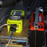
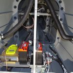 The final configurations of the battery boxes, Artex 1000 ELT, and the Garmin GTX45R transponder/ADSB behind the baggage bulkhead is show here.

