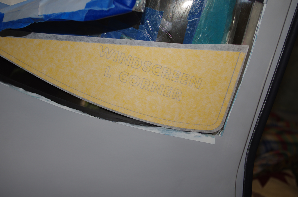
The templates for masking the window transparencies have finally arrived. The Avery Dennision BriteLine+ vinyl sheets were custom cut by Moody Aerographics specifically for this purpose. I originally intended to mask off each window with just one vinyl piece, but matching the template profile on the curved surfaces with the exposed sticky adhesive proved too difficult for an amateur installer. Instead I chose just to use the corners which lay flat, with electrical tape filling in the straight or slightly curves intermediate sections.

 The left photo shows the raw templates on the main roll. Before applying to the windows, an outline of each corner was traced on acetyl sheets. The reason for retaining this contour will be shown later…

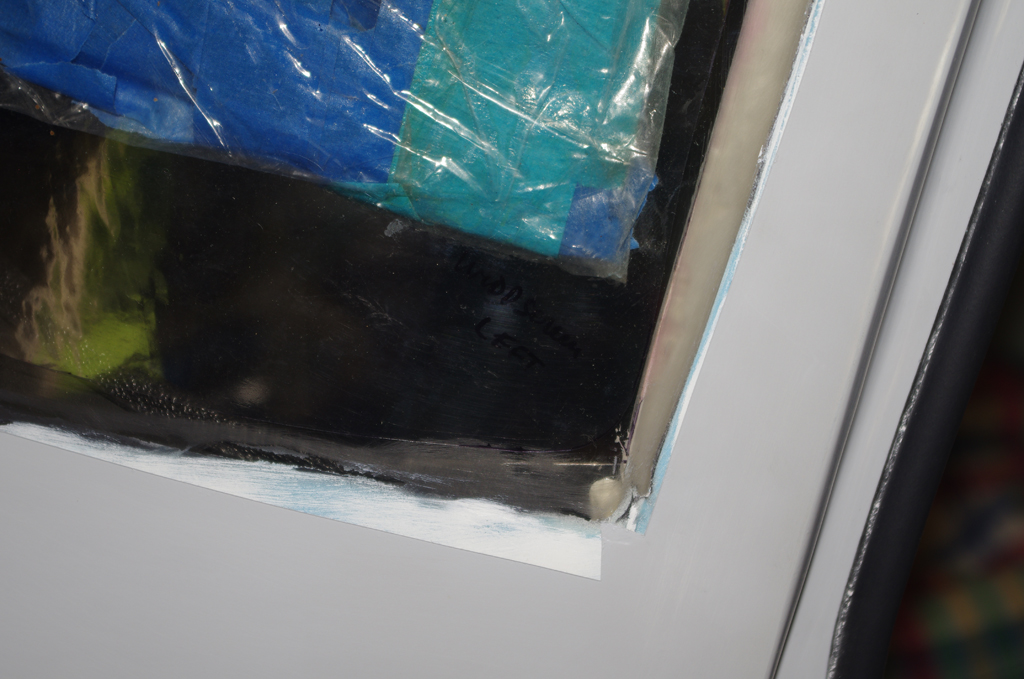
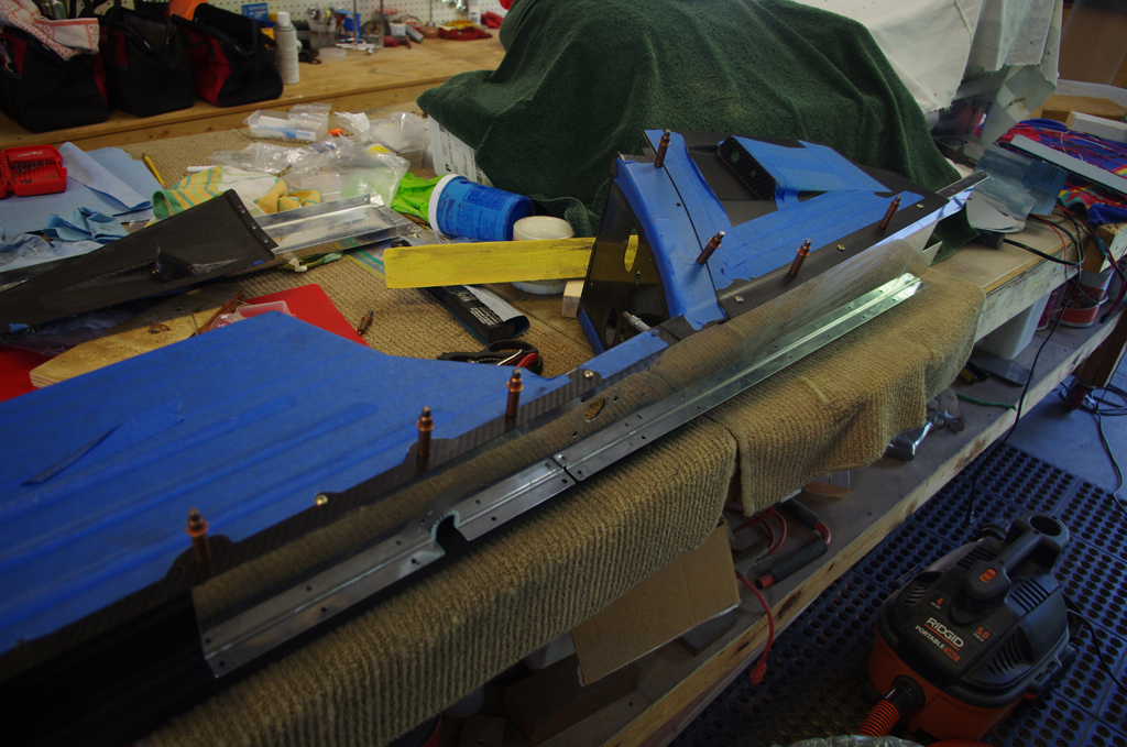
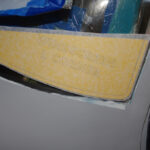 The left lower windscreen corner was raw fit with epoxy resin and SuperFil before priming. The corner template mask was laid into the corner with about 1/8″ – 1/4″ offset from the underlaying canopy frame. This offset will present a clean edge visible from within the cockpit.

 The smoothly cut template mask was covered with two layers of electrical tape. Each tape layer provided an additional 0.0063″ height for when the AlumiLite black dyed and glass bead infused West Marine two part epoxy resin was applied to the edge gap. The resin will then be sanded carefully from layer to layer to reach the final height of the template mask.
TAPING DETAILS
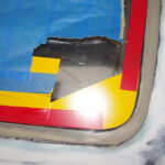
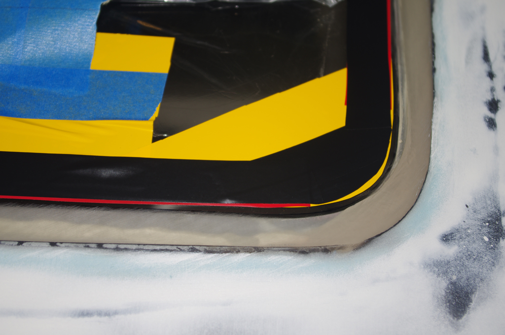
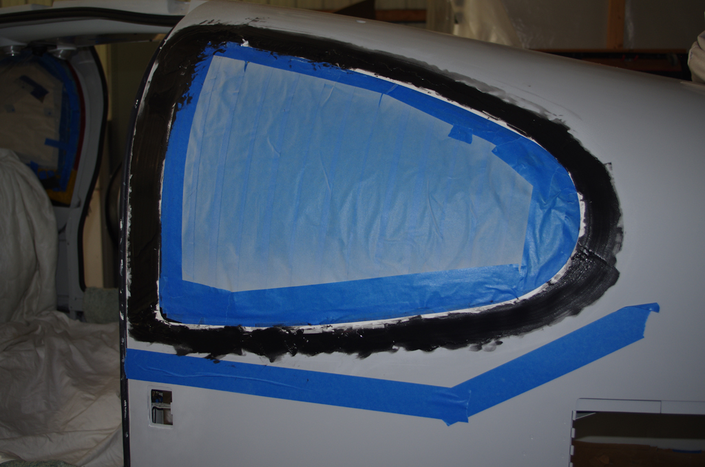
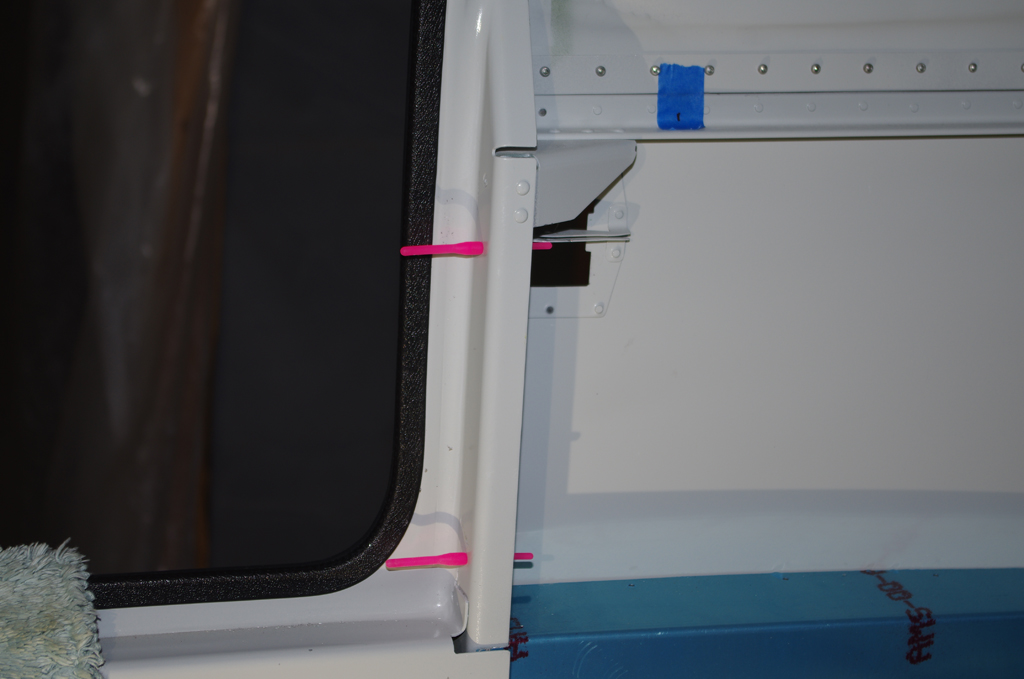
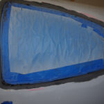
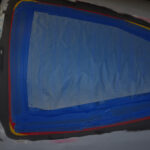
 The same general taping process was then applied to doors and windows. The raw template mask in the corner was connected to other corners with red electrical tape. The bright colors for the final tape layer were used to enhance visibility while sanding. Notice the curved black electrical tape second layer. This shape was rough cut using the acetyl sheet contour described above. Cutting the electrical tape in this manner helps it stay flat, as compared with trying to bend the tape around a tight corner.
 Additional black electrical tape was applied above the straight sections, followed by general masking and one more layer of vinyl tape roughly laid around the perimeter.

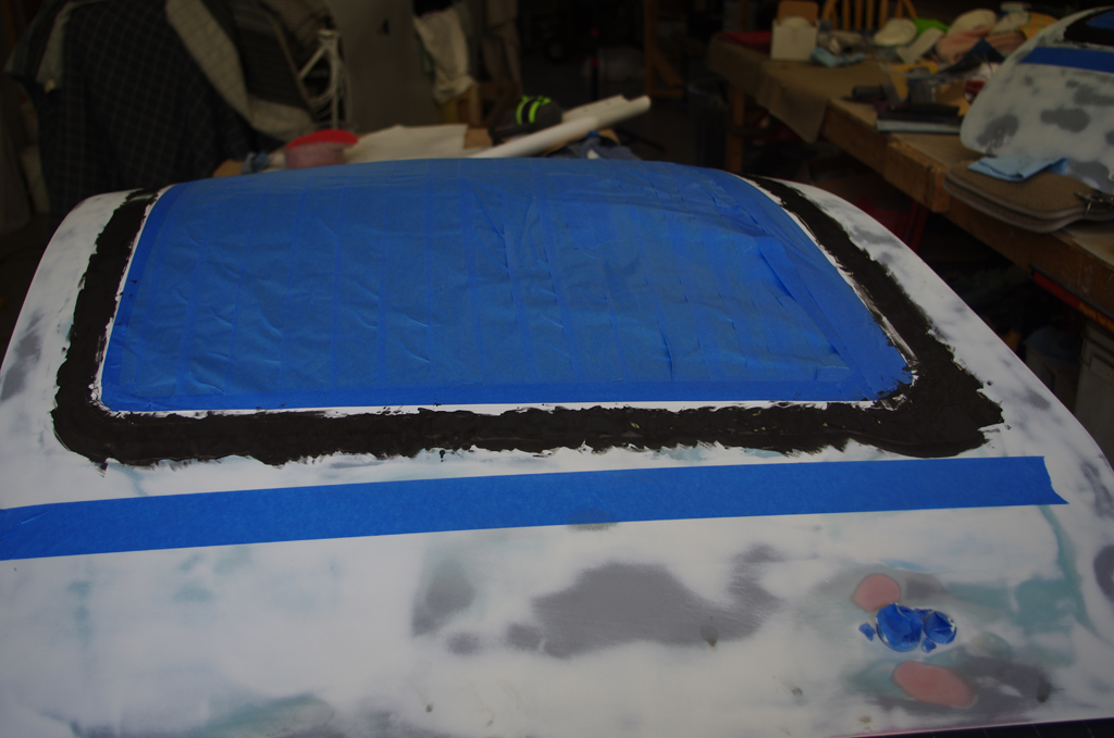
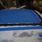 These photos show the before and after initial application of the dyed resin for the front left door.
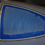
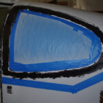 These photos show the rear left window progressing from taped outline, dyed resin applied, initial rough sanding, and final edge sanding.
 The last sanding step levels the lowest tape layer with the resin material. Since this is only about .006″ thick, the care needed to not rub through to the Plexiglass window is extreme. It took quite some time to achieve this on the windscreen, doors and windows. The sanding outcome so far looks good, but application of the primer and paint will show whether the preparations were sufficient.
OIL DOOR LATCH BUTTONS
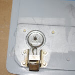
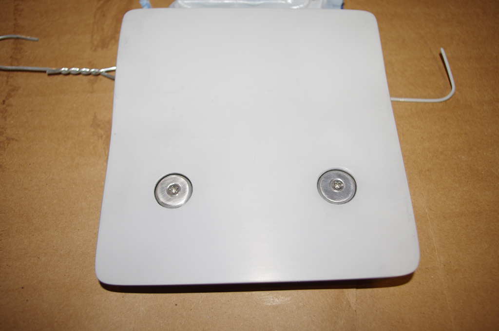
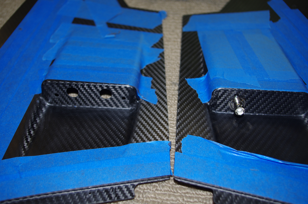
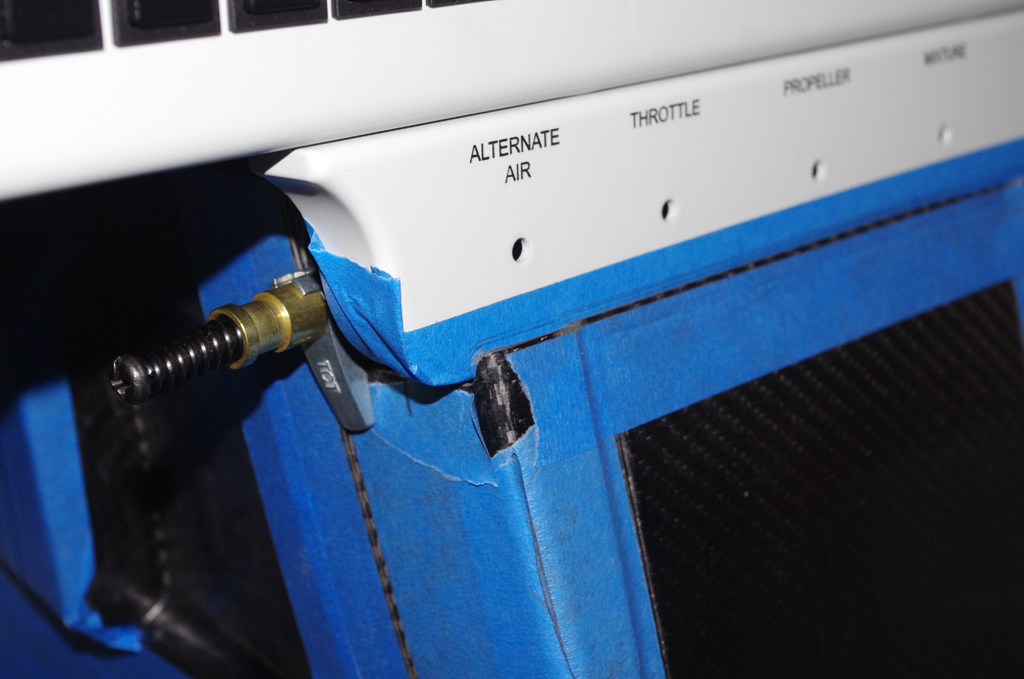
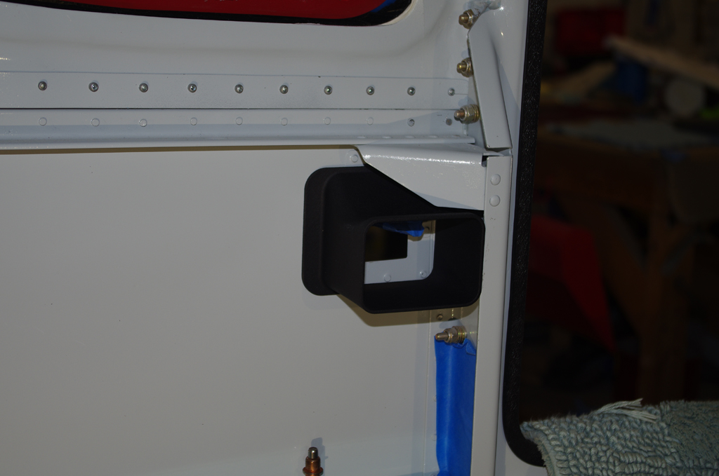
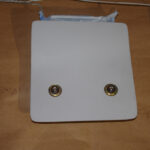 The issue of the push buttons for the oil door has finally been addressed. A #30 hole was drilled into the Camlock latch plate, then taped for a #6 screw. A mock-up of the final buttons (yet to be fabricated) are represented by the washers on the right.
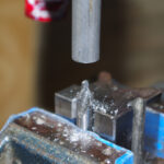
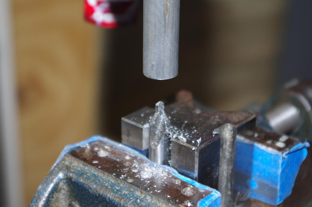
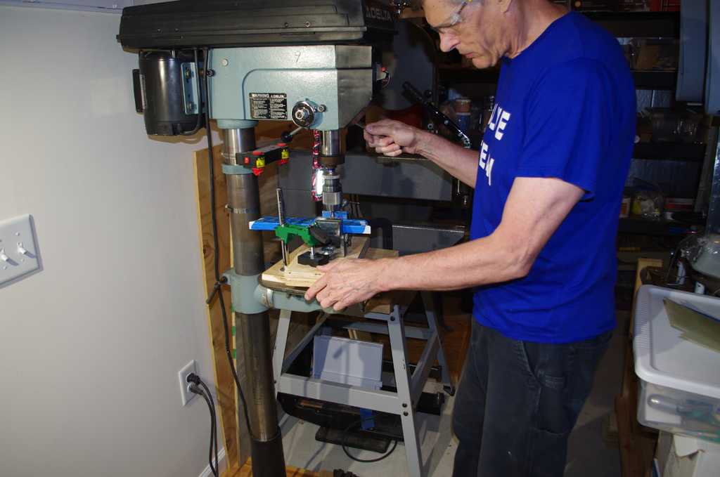
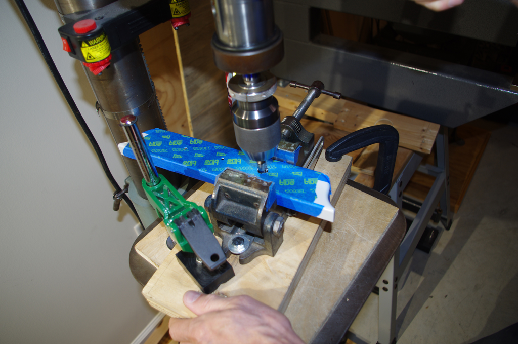
 The Delta drill press and a V-block were used to drill a 1/2″ steel bar with a center hole. That hole was then taped for a #6 screw. The taped post held a piece of 1/8″ aluminum flat bar for shaping.

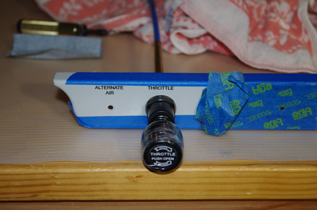
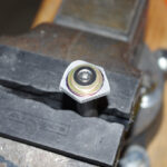
 The blank was hand filed and then sanded to exactly fit into each latch hole. The sides were slightly rounded to self-center the button when the latch springs back to the closed position. The final buttons were polished with 2000 grit sandpaper and fastened with #6 stainless screws. They will probably will be left as-is and not be painted, but that decision will be made later.
MISCELLANEOUS

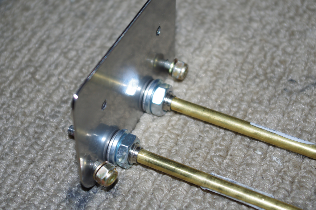
 The original plans call for an AN3 bolt to hold the steps in their cradle. I wanted a stronger connection, so the steps and the cradles were drilled and reemed to 1/4″ to hold thicker AN4 bolts. (NAS-
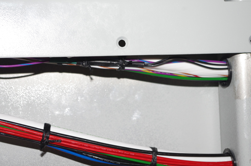
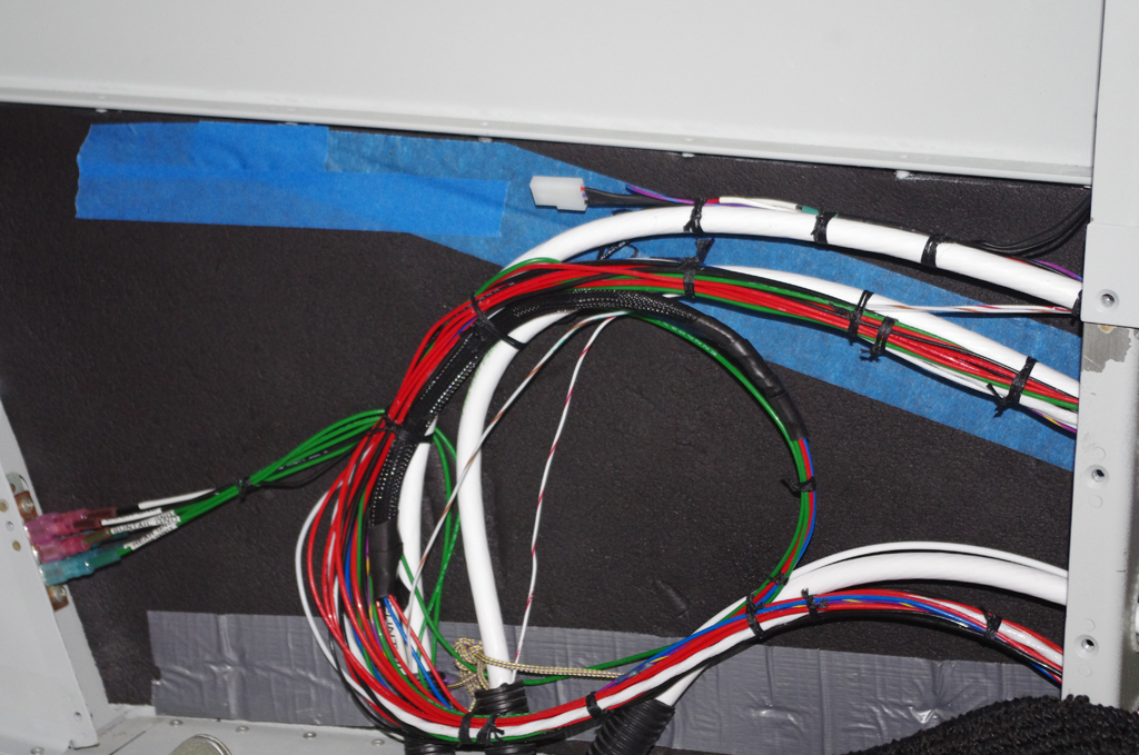
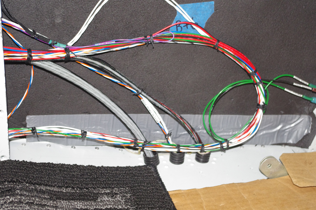
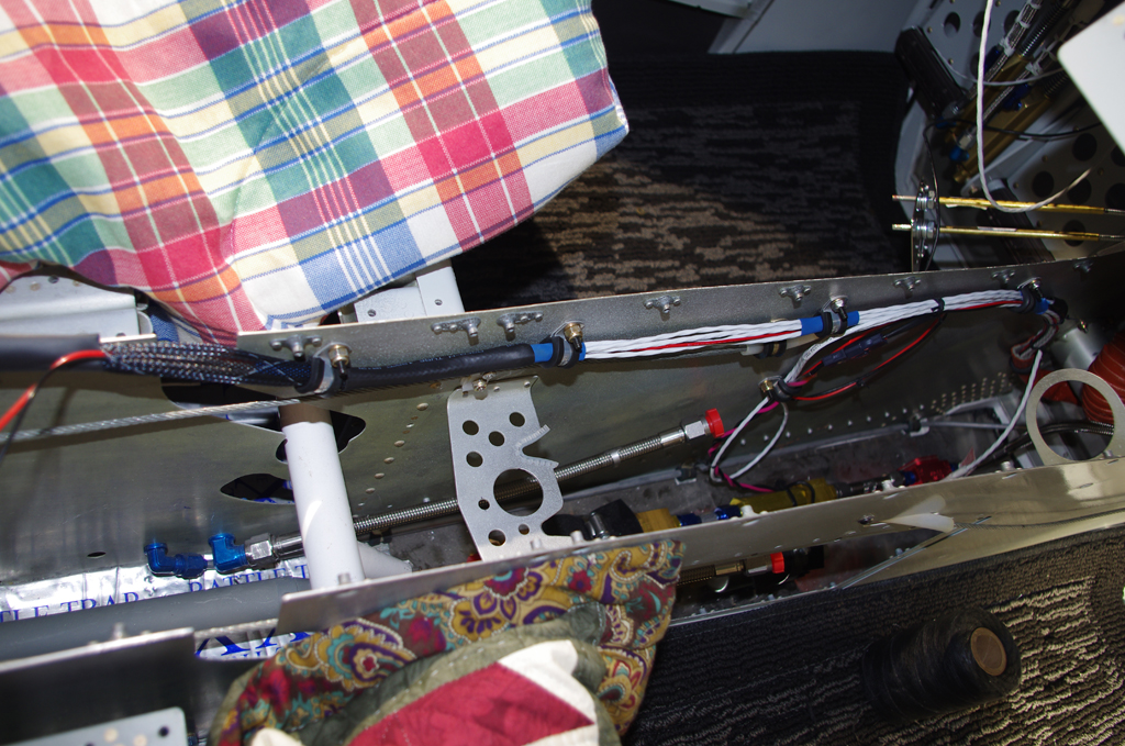
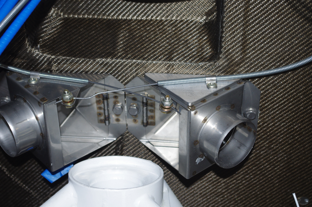
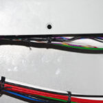 The door alarm reed switches were connected to the main electrical bundle via DSUB connectors. They are held together with heat shrink, then laced into place.

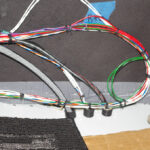
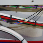
The main wiring bundles on left and right sides under the rear seat panels were laced together. In retrospect I would probably rearrange some of the wire runs for a cleaner look, but the final result is secure and will be serviceable as needed for future maintenance.

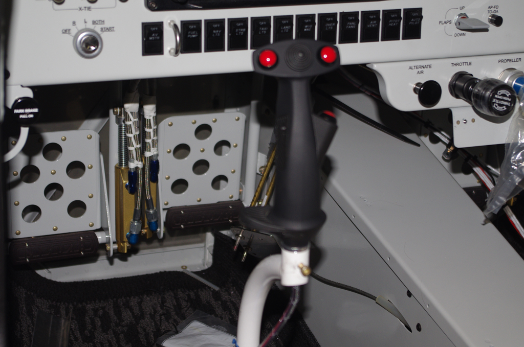
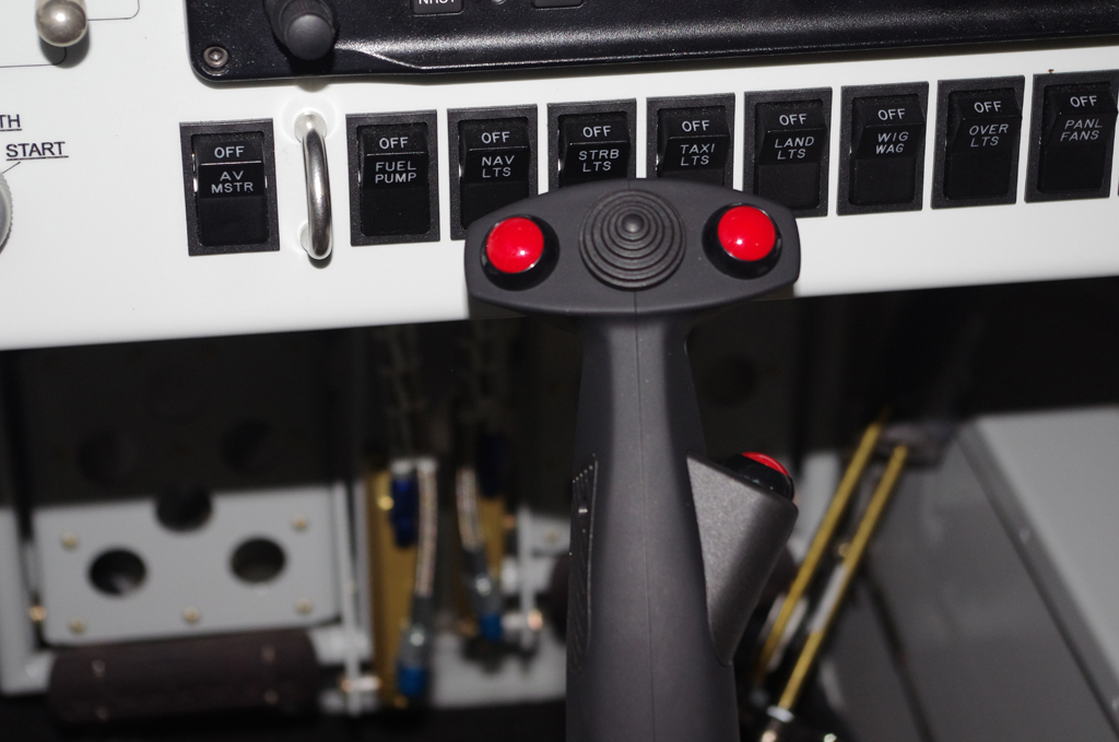
 The control sticks were cut to length to provide the maximum height without touching the instrument panel or switches.

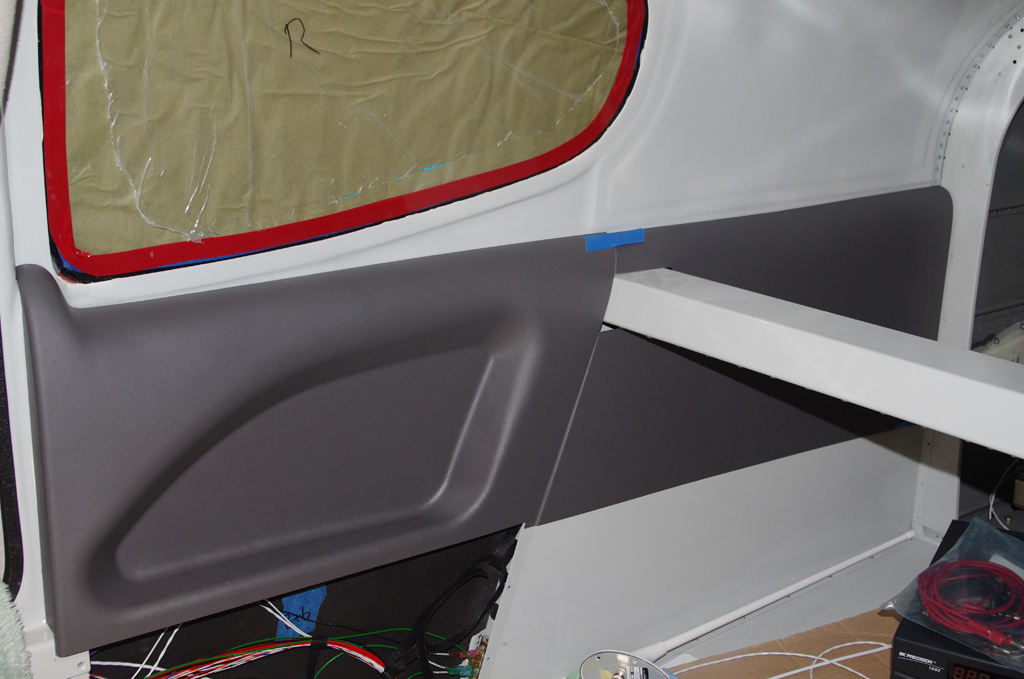
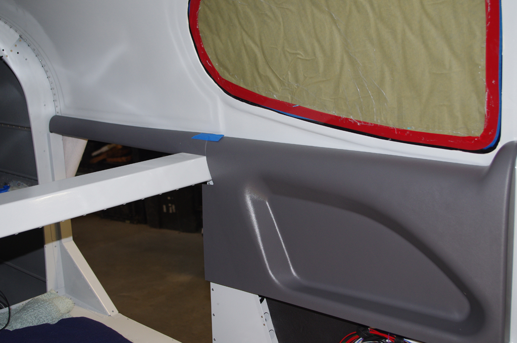
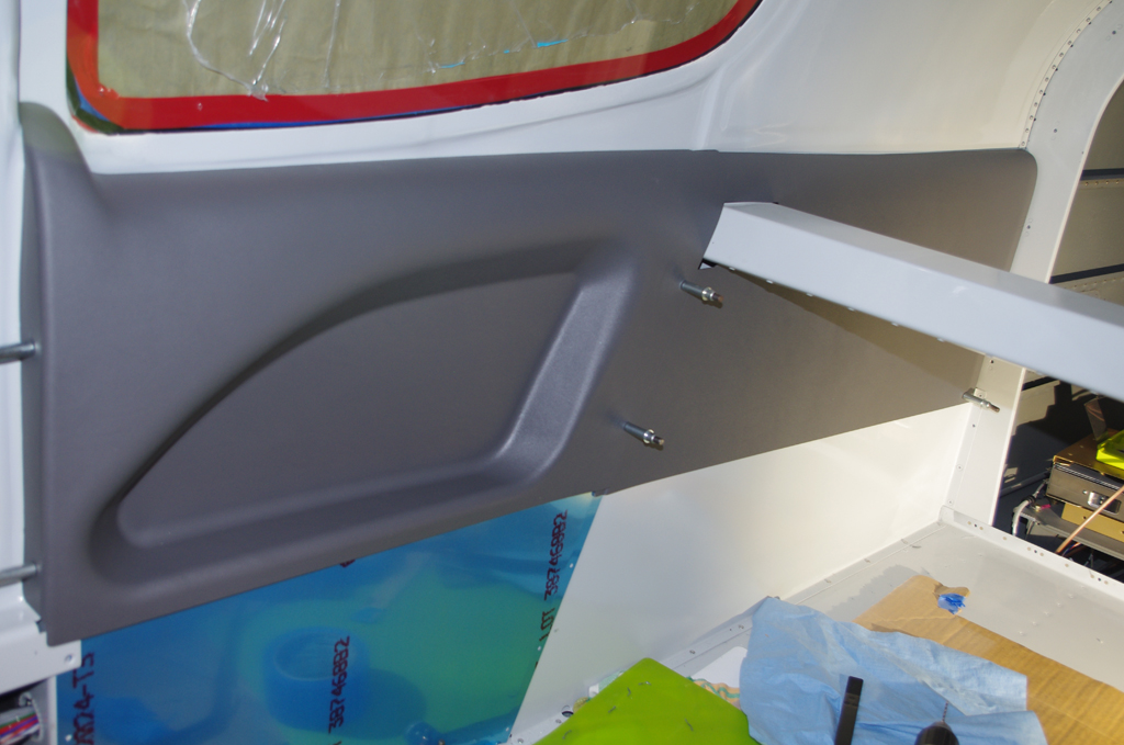
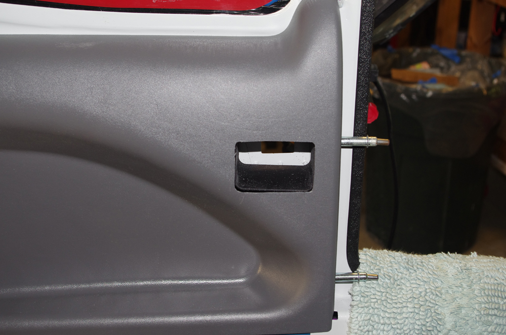
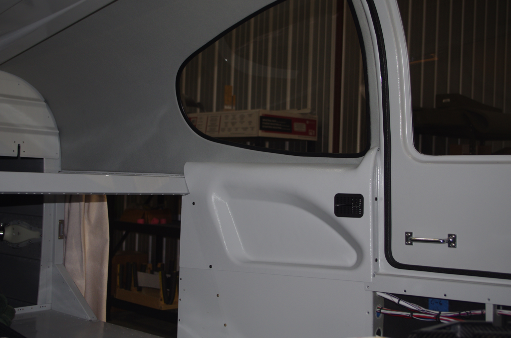
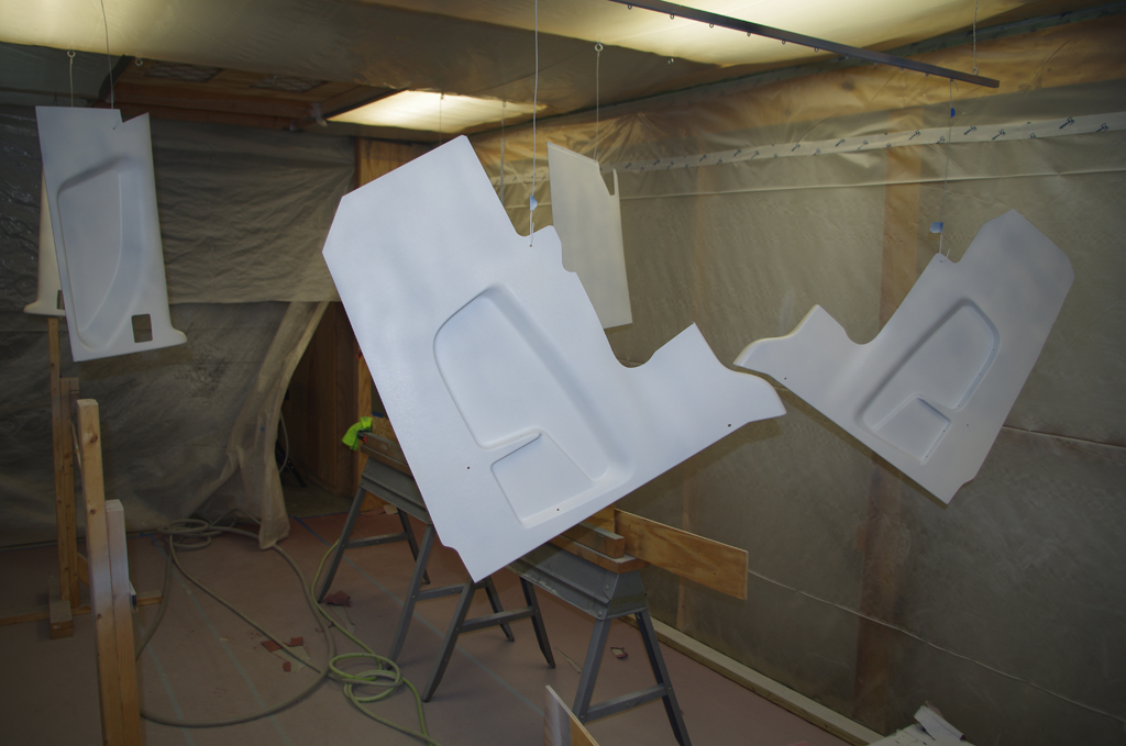 Interior panels from Aerosport Products were primed with PPG DP48LF white primer. Later the panels were painted PPG Concept Boeing Grey.
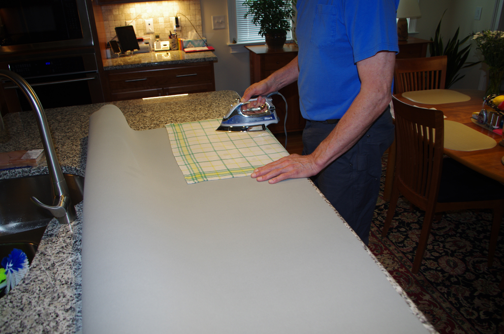
 The foam backed, fabric material was glued into place on the Aerosport headliner with contact cement by professional auto specialists. (Don’t ask why I did not do this myself). The backing fiberglass was then fitted with Velcro strips and attached to corresponding strips on the canopy.
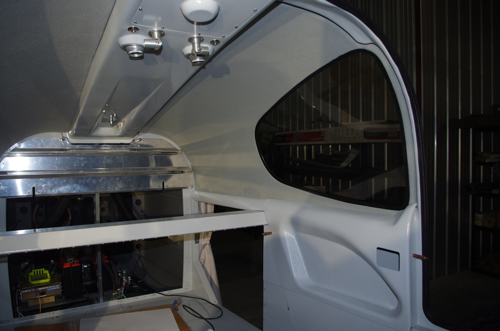
 More views of the overhead console and installed headliner..
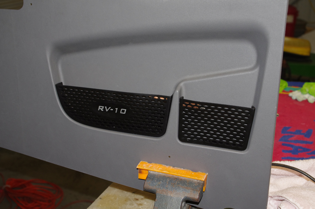
 The left photo shows fitting the map pockets on the forward interior panels prior to prime/paint. The right photo shows the baggage bulkhead after painting.
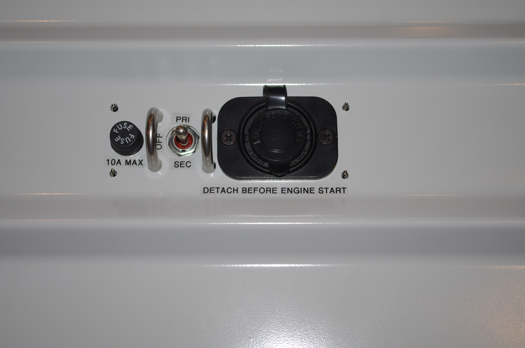
 A Blue Seas power outlet was fitted onto the baggage bulkhead. A 10A fuse and toggle switch for directing trickle charge power to either PRI or SEC battery were installed with switch guards. This outlet is not intended for ever jump starting the aircraft. The required EXPERIMENTAL decal was installed on the upper bulkhead cover.
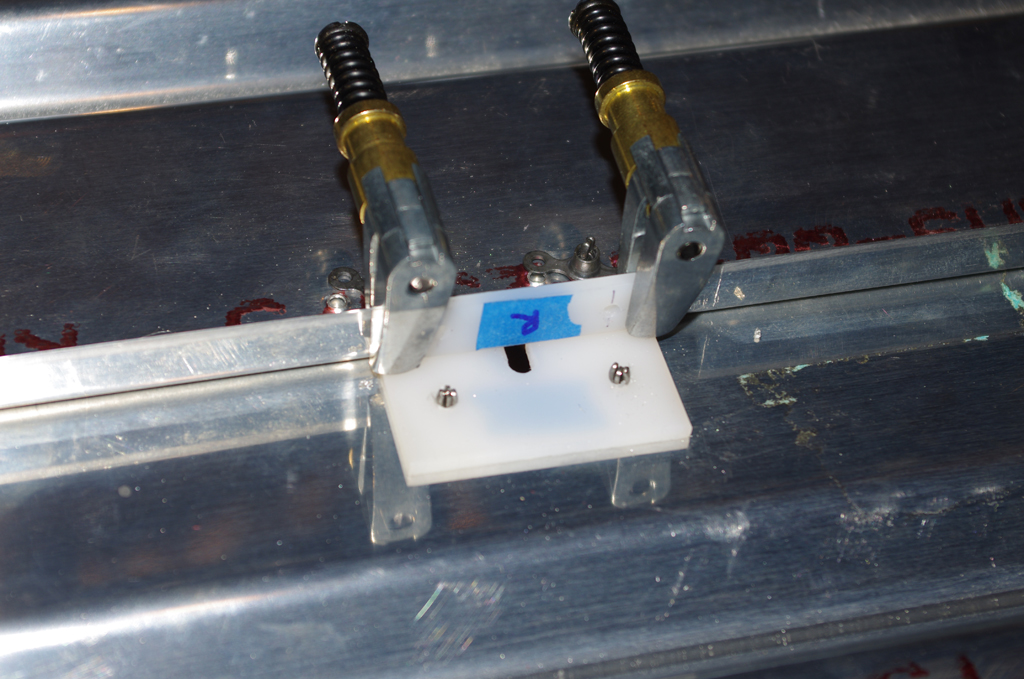
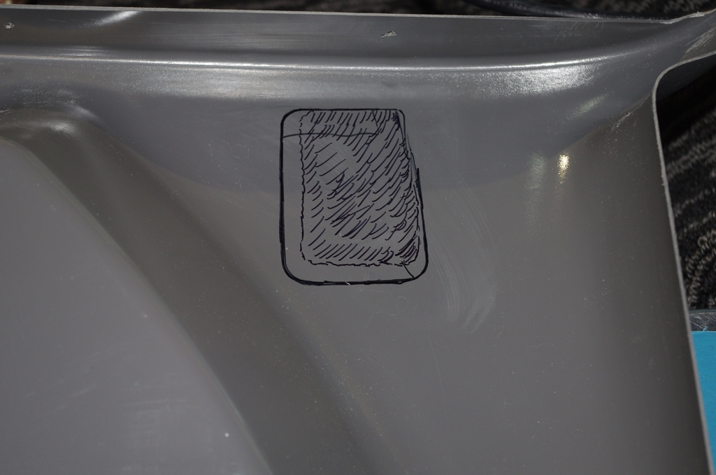
 The lower bulkhead cover was fitted with UHDP wear blocks for the rear shoulder harness cables. The right picture shows a rear interior panel with the air vent cover installed.
 Preparation of the Aerosport dashboard cover included installation of covers for the panel fan outlets and trimming the edges for fit. After trim, I used my fledgling sewing skills to dress the edges against fraying.
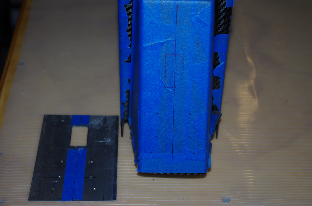
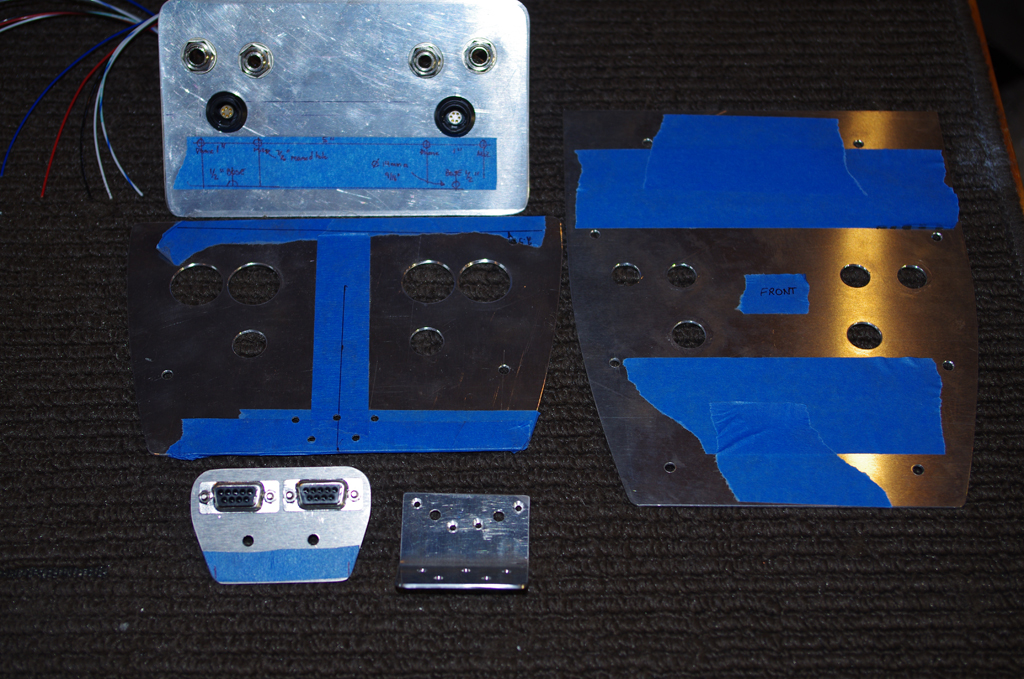
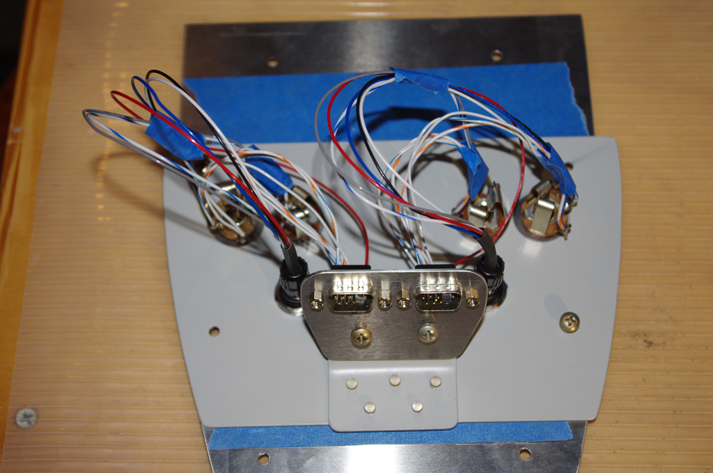
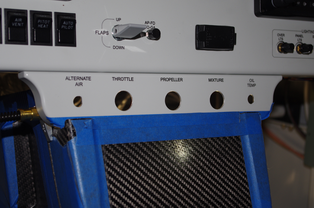
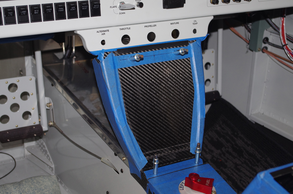
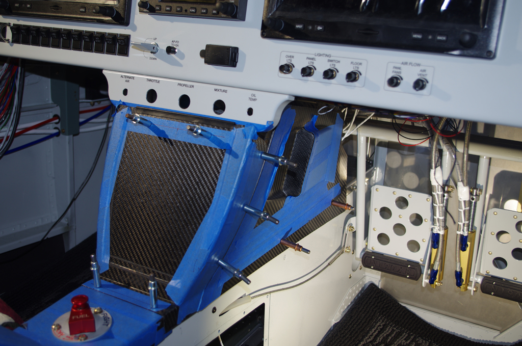
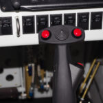
 The center console and control stick wiring was completed and tested. Labelling of the jack ports was with a Brother P-touch. I would have preferred a laser etched alternative, but maybe than can be a future project.
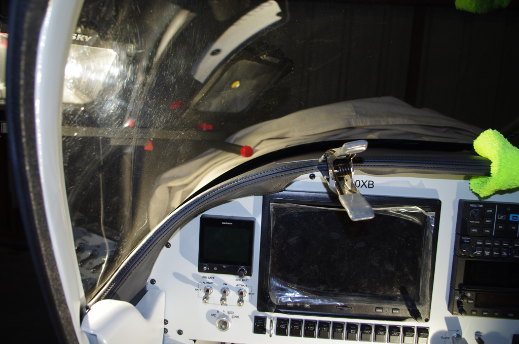 The dashboard cover was secured with 1″ and 2″ Velcro strips.
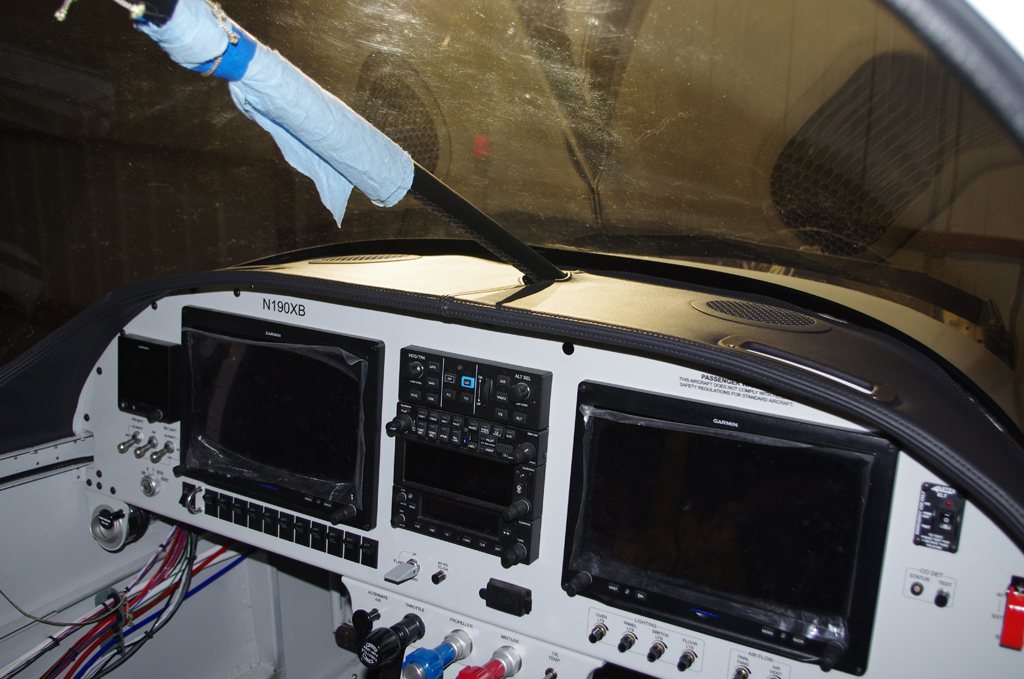
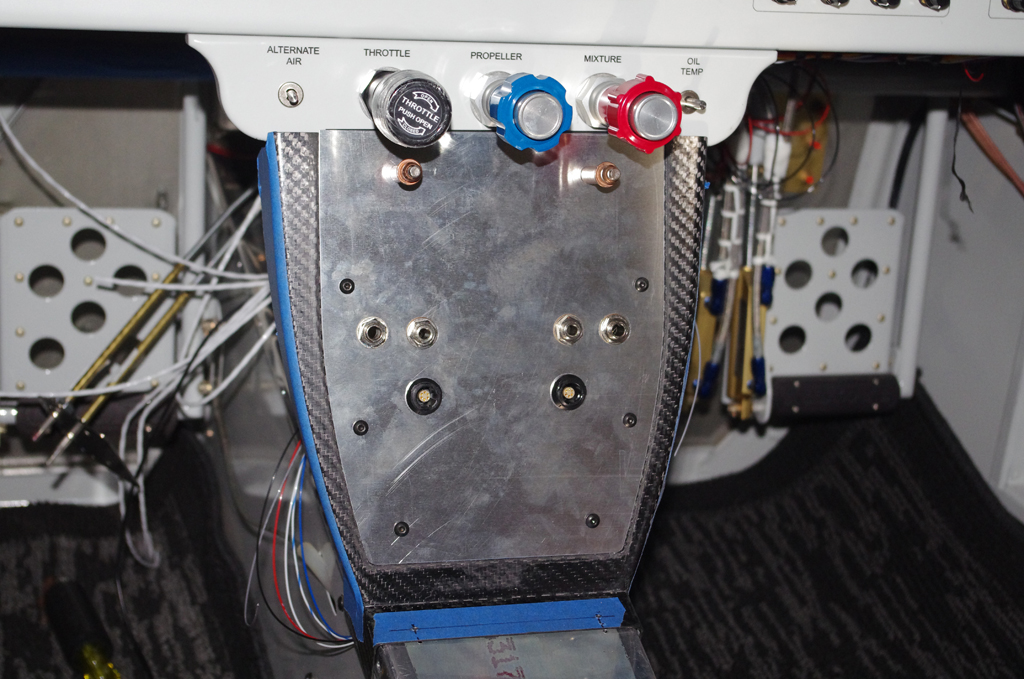
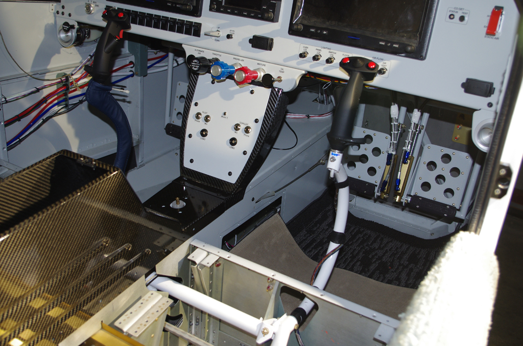 Final dashboard cover, center console and control sticks installed…
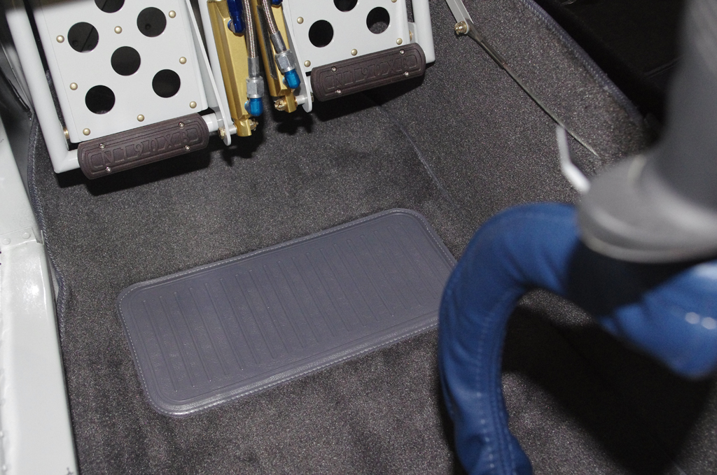
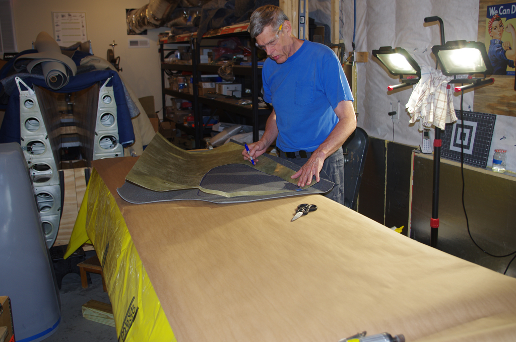
 Front and rear footwell carpet…
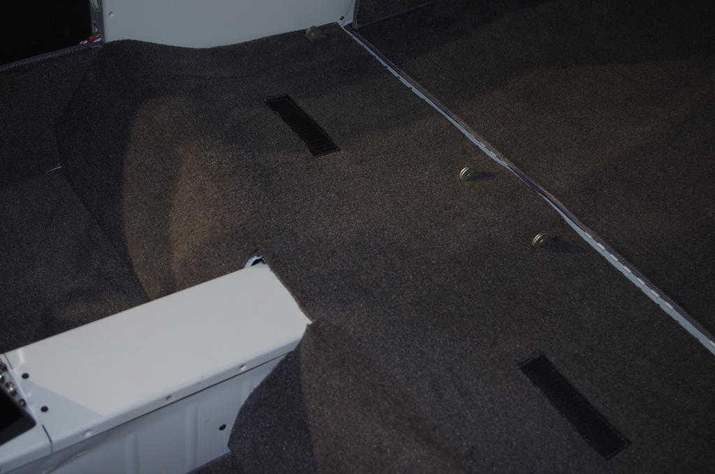
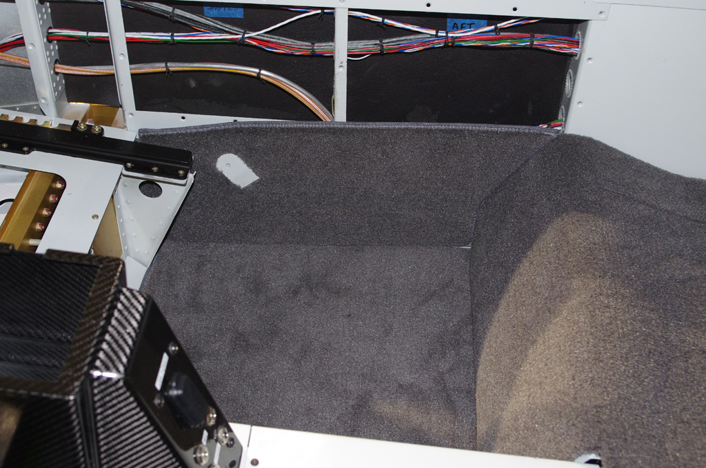
 Rear seat and baggage compartment carpet…