Monthly Archives: September 2022

You are browsing the site archives by month.

Wing Attachment (2)

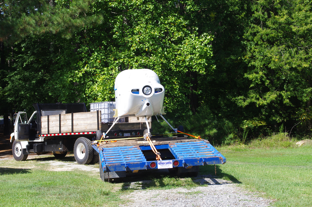
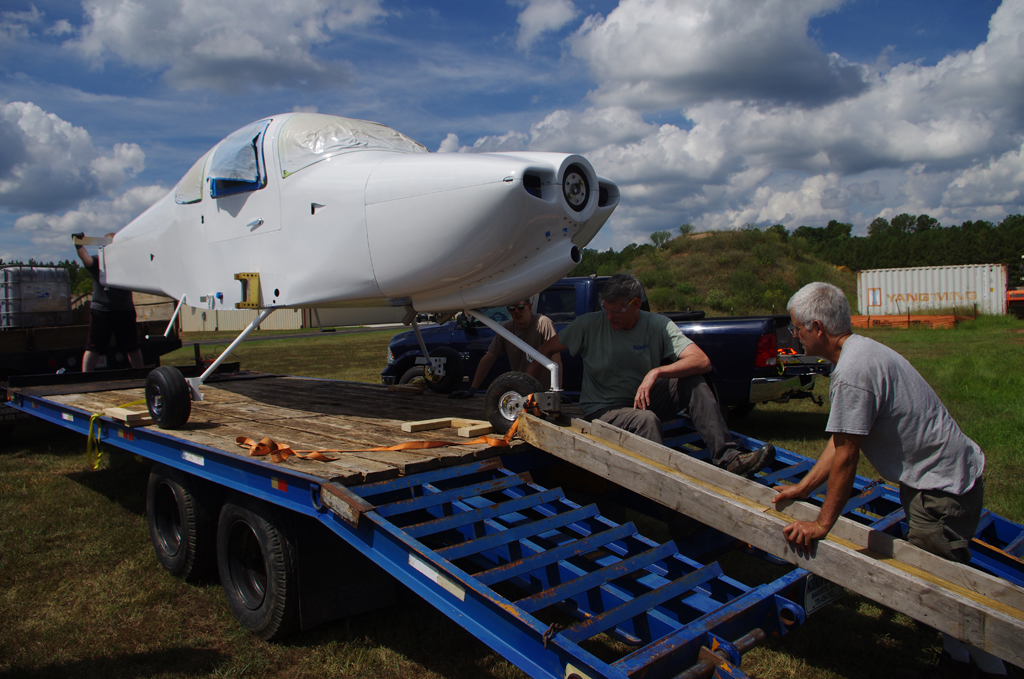
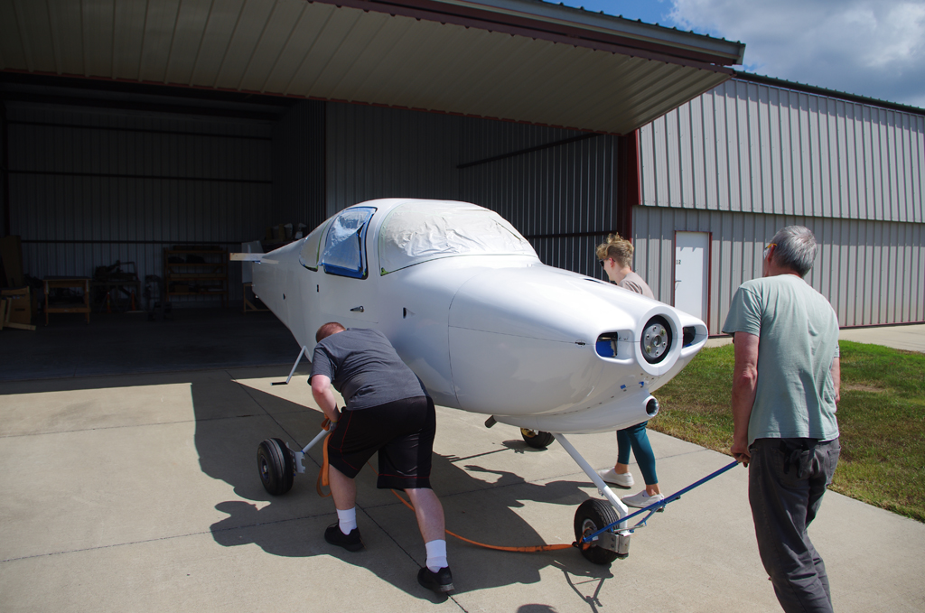
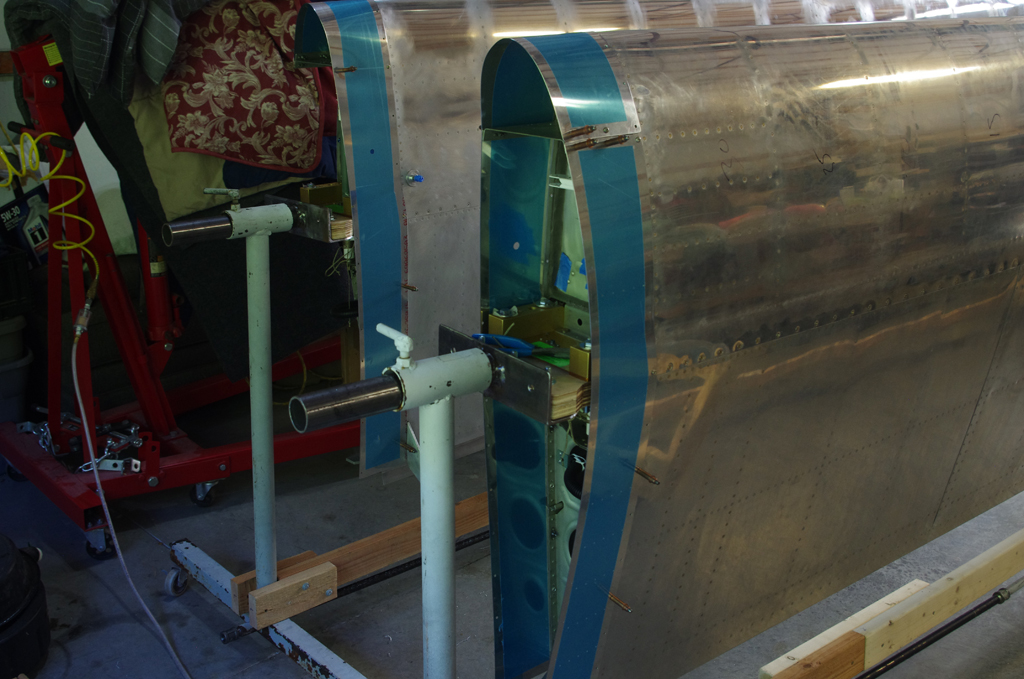
The same day as ‘the big move’, we attached the wings with provisional fasteners, then began work fitting the wing root fairings.

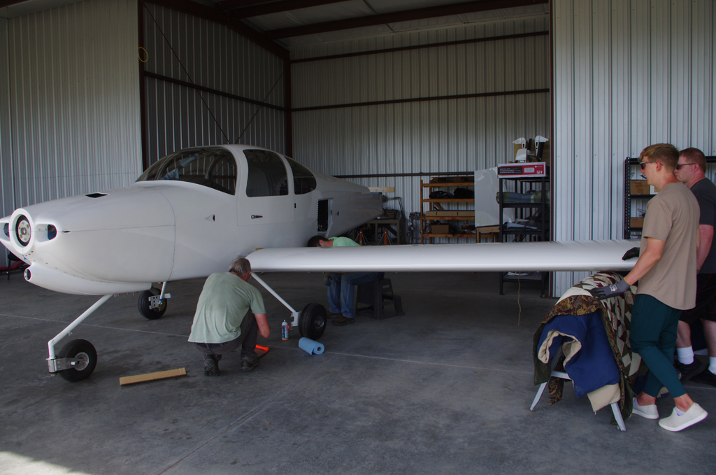
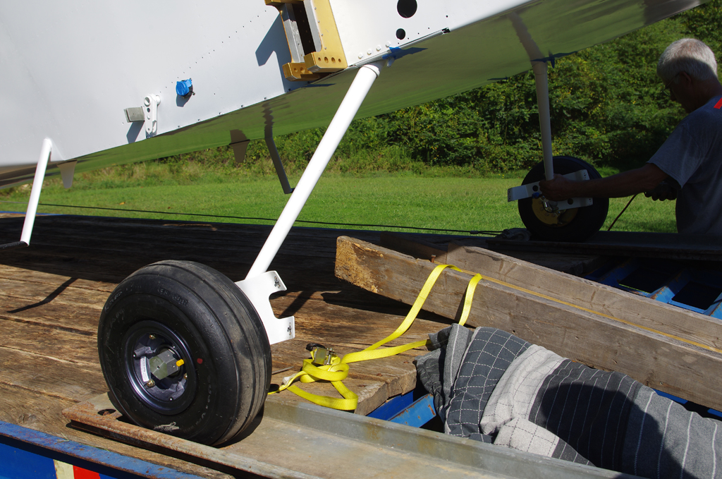
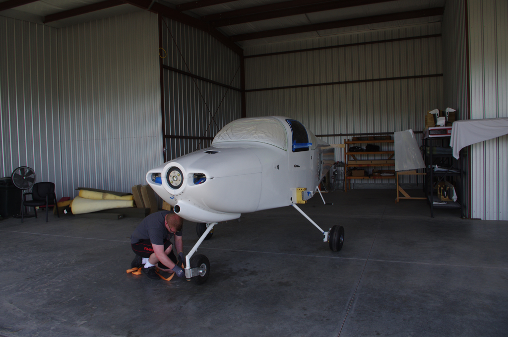
Following the Van’s instructions, the wings were first pinned into place with drift pins and hardware store 3/8″ bolts. These bolts have much looser tolerances (~.010 “) as compared to the high precision NAS1309-58 and NAS1306-58 bolts called for final insertions (done at a later date).


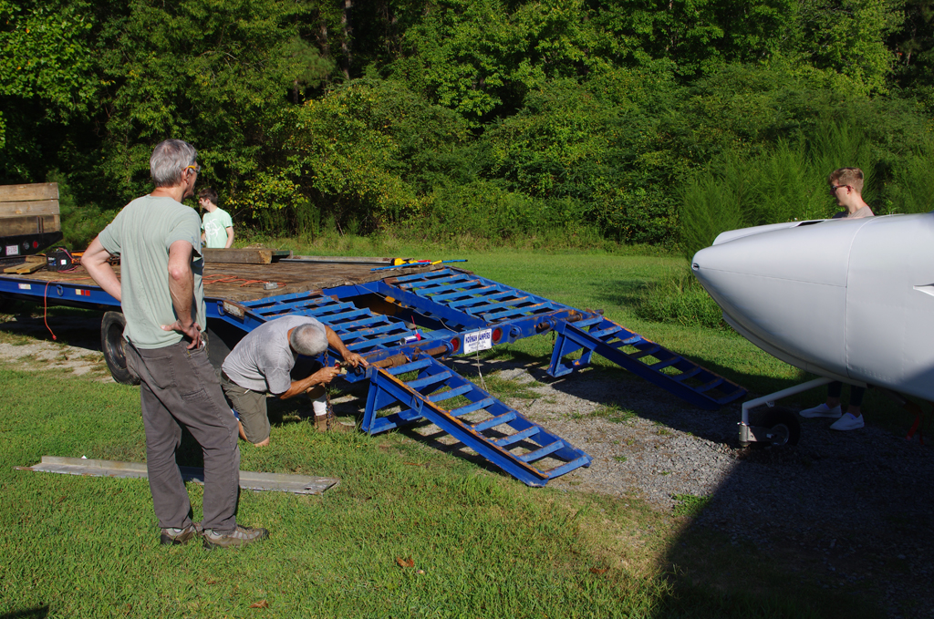
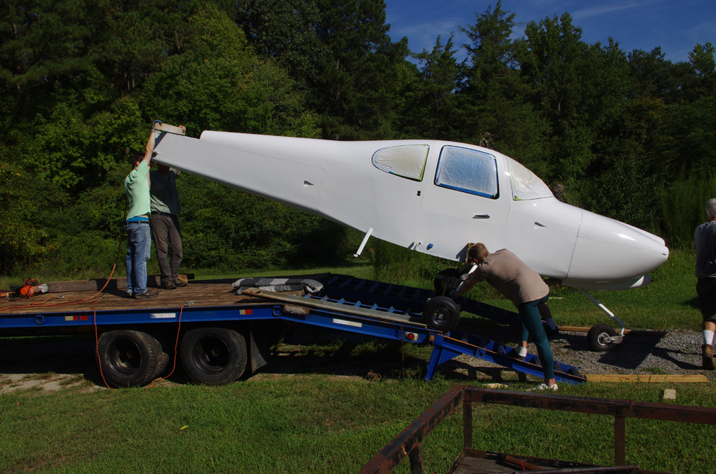
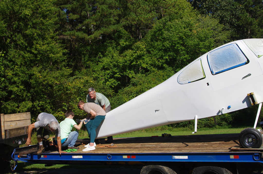
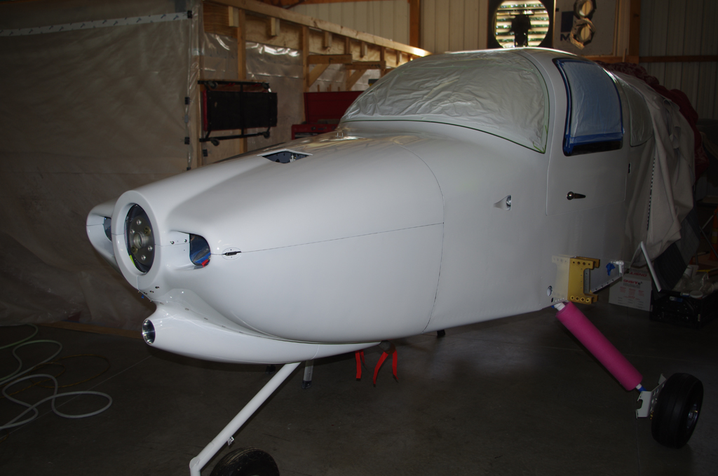
Both wings were provisionally attached with just a few main bolts. Thanks to Eric, Peter and Aaron for help during the wing transport and attachment activities.


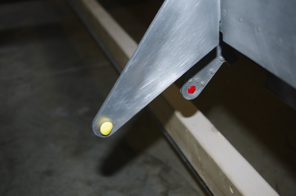
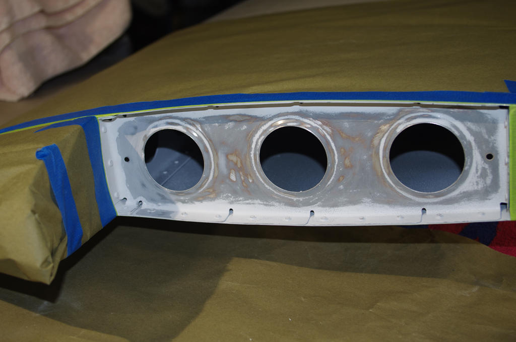
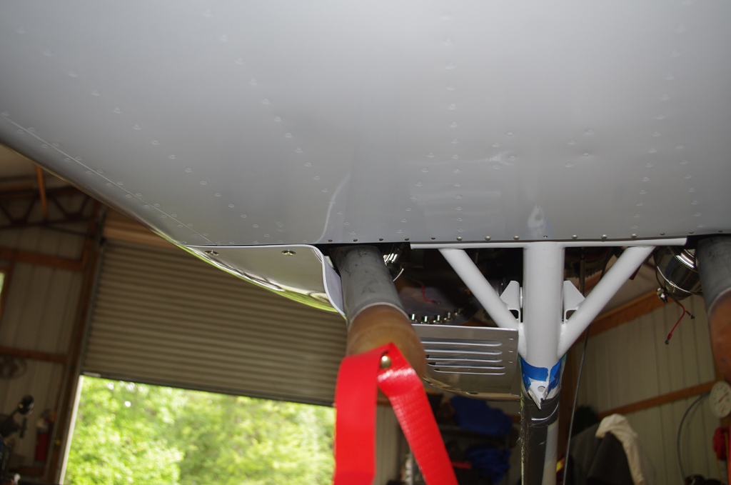
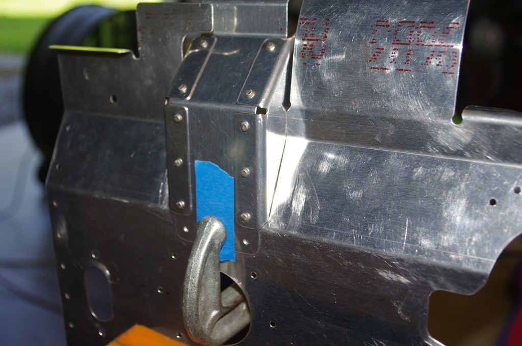
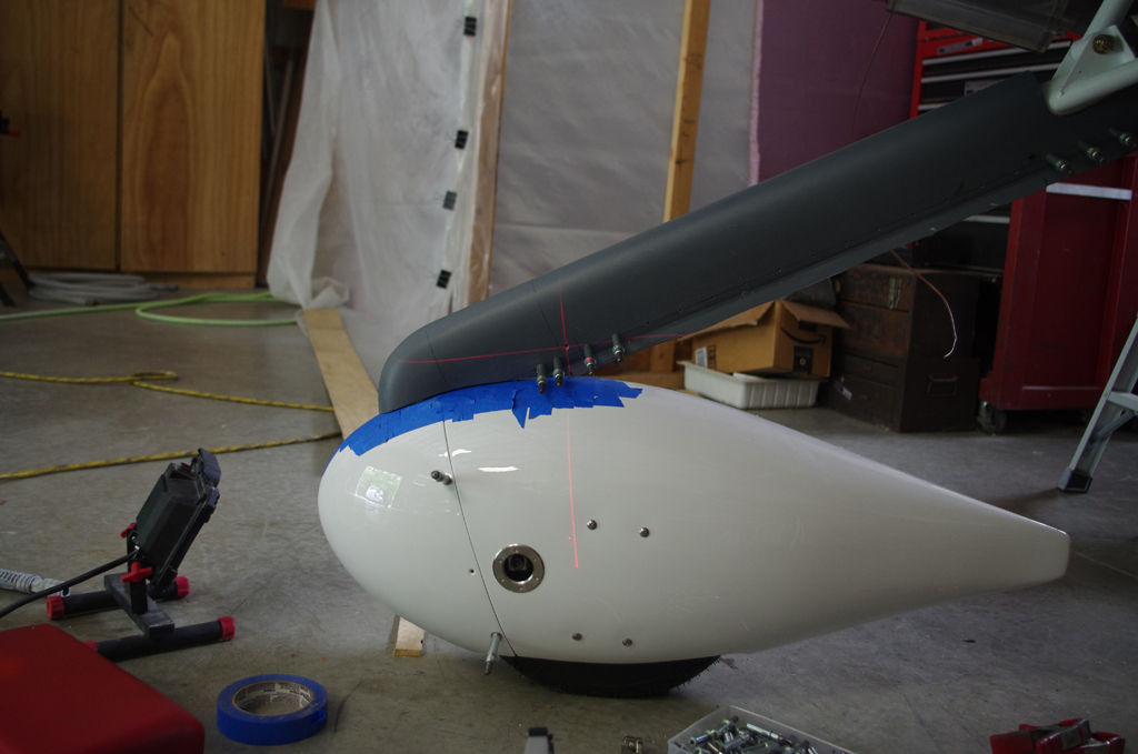
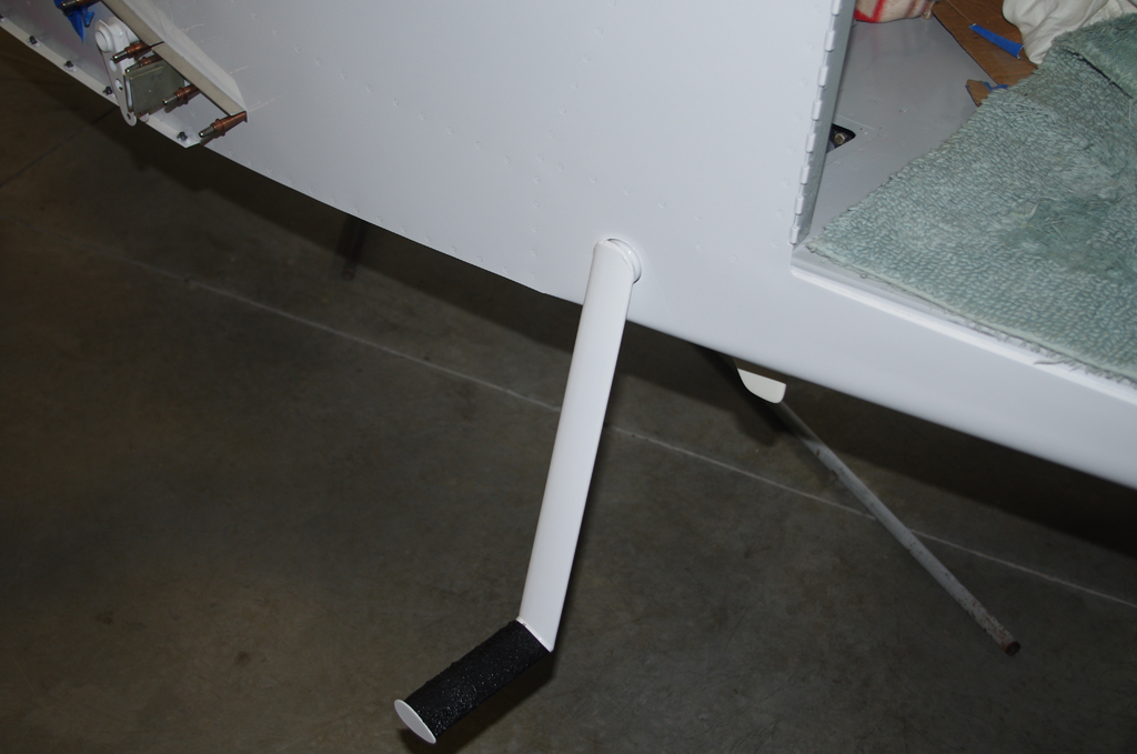
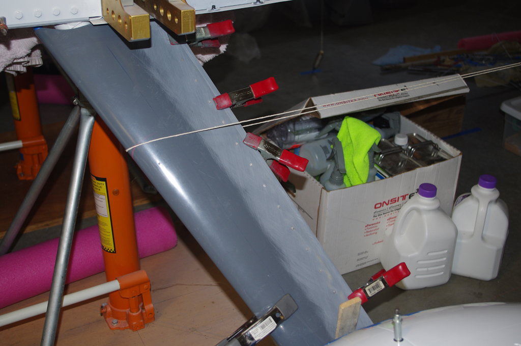
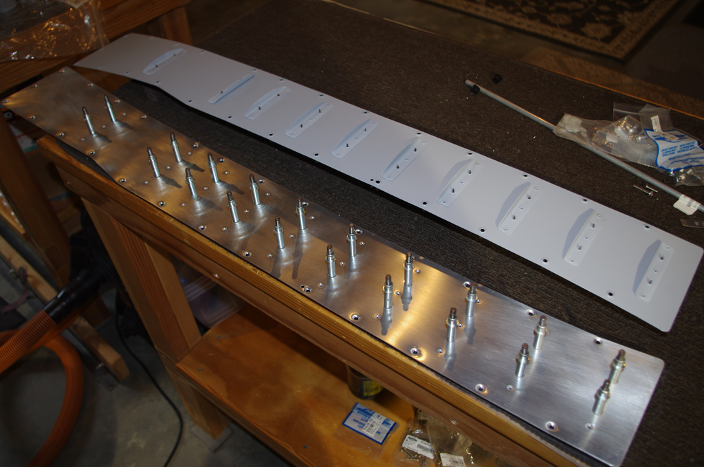
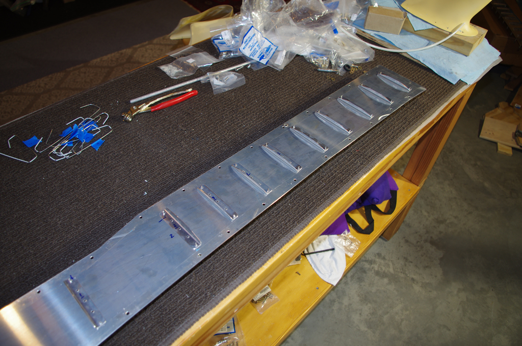
The wing root fairings were trimmed to match the contour of the fuselage. This left about a 3/16″ gap between the fairing and fuselage. This gap will be filled with black rubber edge molding as some vibration and flexing of the wing will be expected during flight.  On the right stiffeners, upon which people will stand when entering the cabin, are clecoed then riveted onto the upper fairing panels.


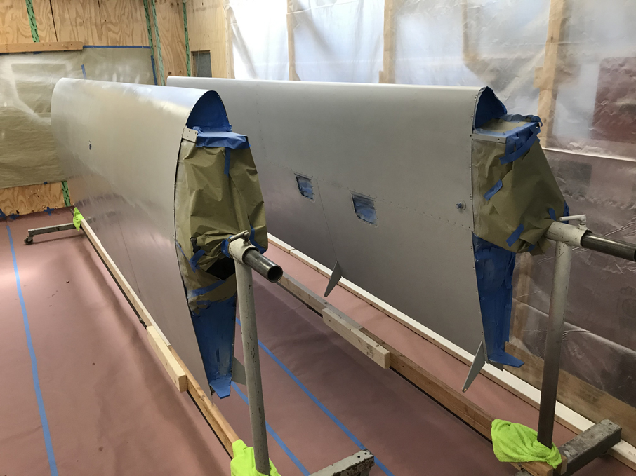
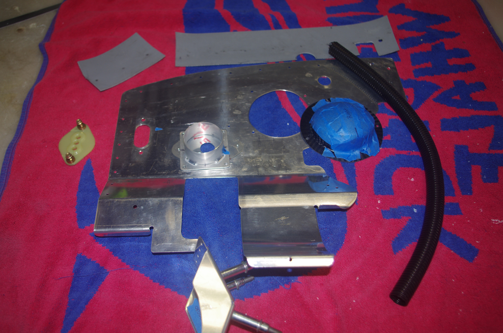
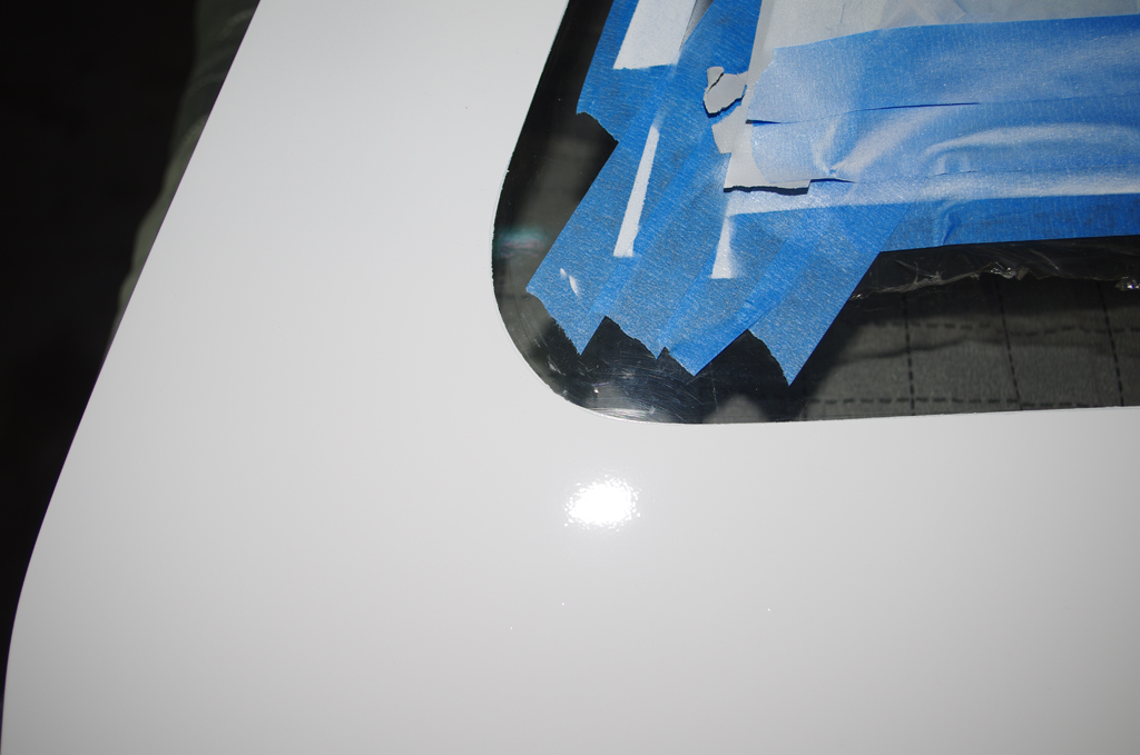
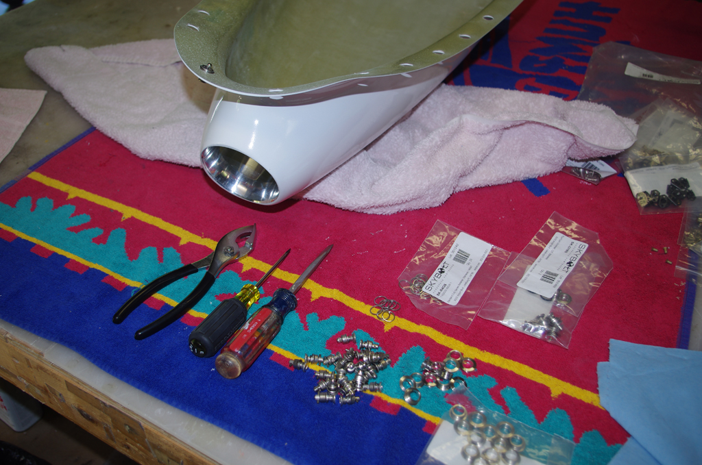
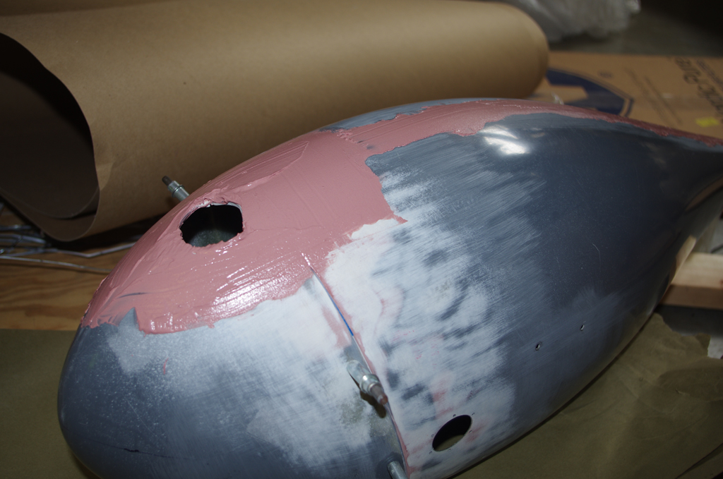
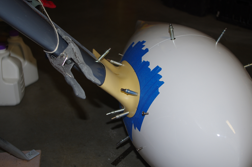
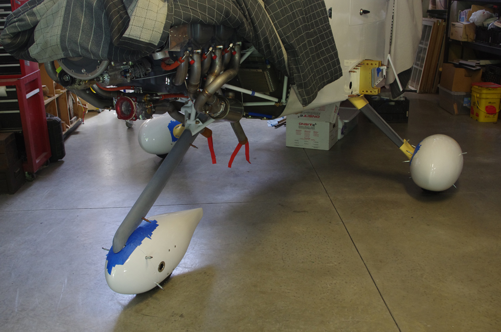
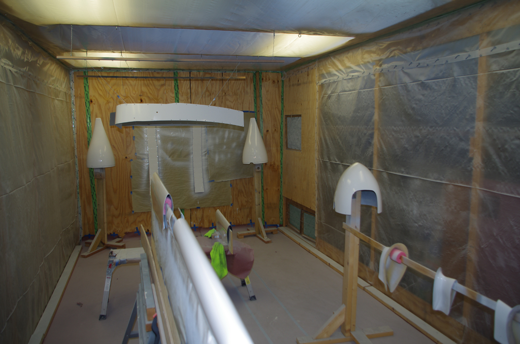
The inner sides of the fairings were scuffed, washed and then sprayed with SEM Self-etching primer (grey 39683). The outer sides were scuffed, treated with Prekote, then primed with DesoPrime followed by application of Snow White Desothane CA8800 paint. Wheel pants and fairings were painted at the same time.

Logistics (Fuselage and Wing Moves)

The 2022 Labor Day weekend saw the transportation of fuselage and wings to the final assembly location in my hangar at KTTA.  Many thanks to Terry G. for the use of his equipment, his expertise and patience in dealing with a very nervous builder (me) during the “Big Move”.

The cowl was attached to the fuselage for transport, then pushed outside the shop to be loaded onto a 22′ heavy equipment trailer. Initially we intended to load the plane facing forward, but found rolling it on backwards would be much easier.


The trailer was about 8’6″ wide, but the main landing gear wheels were about 8′ even.  As a result, the movable ramps had to be relocated outwards to accommodate loading the plane. An electrical winch attached to the tail cone started pulling the fuselage up the ramp.  Eventually the pull angles were wrong, so we used the body weight of two people to hold down the tail while others pushed the main wheels between grates on the loading ramp.


Loading was a very slow, deliberate process as the leeway between main wheels and edge of the trailer was only about 3″ on either side. The fuselage was carefully inched backwards up the ramp and into position.  A wheel coming off the trailer would have spelled disaster and could have ruined the entire fuselage.


More photos inching the fuselage onto the trailer.


Eventually the main wheels were chocked close to each edge.  Multiple ratchet straps held down the main and front wheels. These were tightened into a very stable configuration; one secured from movement in all directions (left, right, forward, backwards, and up).


Rolling down the highway towards the airport!  The actual road transport went without any issues with a safe arrival at the end.


Multiple volunteers helped unload the fuselage – basically the reverse of the load process, but much easier with the gravity assist.  Here the fuselage was moved off the trailer…


… and into the hangar.


Now that the ‘big move” was complete, the protective film on the windows was removed.


WING TRANSPORT

The wings were moved to the airport with Tal’s trailer just as previously posted from house to shop.


Wing Attachment (1) (Paint)

Painting the wings required about three weeks of preparation, surface treatment, and priming prior to paint application.

Custom wing rotisseries were created by Terry G. specifically for RV wings.  I created some special attach plates to directly accommodate the RV10 wing bolt patterns. Here the wings are mounted, scuffed with maroon Scotchbrite pads, and treated with Prekote before priming with DesoPrime Grey.


Prior to scuffing the wings I fitted the outboard side of the wing root fairings, but made a mistake by dimpling one of the nutplate holes in the wrong location. The nutplate still went on fine, but did not align perfectly with the pre-drilled holes in the Vans cover piece.  In the long term this is not a big issue, especially since this area will be covered by wing walk material anyway.  However, it was aggravating not to have paid close enough attention to the plans.


Fastener holes for the flaps and ailerons are filled with ear plugs or electrical tape to prevent covering with primer or paint.


After initial prime and paint a few runs and poor coverage were discovered.  As a result the wings were wet sanded with 600 grit, then repainted.  The final results were very good.


Here the wings were ready for the move to the airport.  They had been painted 2 weeks before and were allowed to cure completely before being taken on the highway.


HS RESPRAY

The original quality of the HS tip bulkhead paint did not meet expectations.  So while there was extra paint available from repeat covering the wings, I decided to redo the ends.  Here the ends are shown sanded and ready for another coat of primer and paint.

Firewall Forward (1)

A variety of firewall forward components were added between paint preparation stages.

Here the standard oil plug was replaced with a quick-change unit.  Note the new unit is secured with .032 Safe-T wire tool.


Next the throttle and mixture levers were adjusted and tightened to final configuration. Castle nuts secure the levers and jam nuts immobilize the push-pull cables.


The sensor manifold contains units for oil (150psi), fuel (75psi) and MAP pressure (30psi).  All sensors were sealed with fuel resistant lubricant and torqued to appropriate tightness.  The manifold block was then fastened to the firewall through pre-installed (QB kit) AN3 nutplates.


The oil cooler unit was installed and feed lines attached from the engine block.  The right photo shows the manifold pressure line teed for a line to the Surefly magneto, which has the ability to adjust ignition timing based on MAP pressures.


A further complaint from many builders is oil leaking from the standard tube/hose/clamp configuration on Lycoming engines from cylinder heads to oil sump. I obtained the flexible SS hose kit from TSflightlines, then added fire sleeve myself prior to installation.  Two notes – the fire sleeve was probably not necessary (overkill on my part), and access to the oil sump fittings was much easier without the exhaust headers being installed.


This shows a provisional install of the primary alternator drive belt (Gates XL 7360). Final tightening of the belt and torquing the retainer bolts will occur once the propeller has been mounted.


The right photo shows the open ports for CHT probes in the cylinder head, plus the .032″ safety wire approach used to hold the forward cylinder baffle flange. The other photo shows the CHT probe installed with 30 lb-in torque (as per manufacturer instructions). The probes still need to be attached to the GEA24 engine monitoring system.


Exhaust headers and exhaust pipes with heat muffs were installed. Then 2″ SCAT tubes were connected between the engine baffles and the exhaust muffs.  Finally additional SCAT tubing was run to the heater vent distribution box.


The exhaust pipes have a flexible ball connection with the rigid exhaust headers. An isolation kit resides between the engine mount and exhaust stack to correctly position the output orientation. It also serves to keep high temperatures off the engine mount.  About 1/2″ – 3/4″ separation was achieved between the exhaust pipes and the lower cowl sections. Later the cowls will be covered with a thin ceramic blanket and reflective aluminum shielding to keep engine heat from discoloring the cowl paint.

Cowl Baffling (3) and Miscellaneous

The cowl attachment points, pins and finalized baffling were performed throughout the last three month period as time permitted and was available between paint/prime sessions.

Many RV10 builders have reported the #5 cylinder chronically has the highest CHT temperatures – mainly due to the lack of airflow over the cylinder head.  One of the solutions mentioned in the forums is apply the RV14 baffle mod to correct this situation.  Here the mod is laid out and provisionally fit on the standard right-rear baffle.


These photos show front and rear views of the installed RV14 mod.  Note the carbon fiber motor mount covers from Aerosport Products.


Another issue reported by many builders is the extreme heat generated by the heater muff during normal operations. One solution is throttle the intake air flowing to going to the heater access tubes.  I added restricting plates to the front and rear heater inlets which can be removed by loosening only two screws..  The volume of air going through these openings can now be easily adjusted.


Attachment of the Aerosport low profile handles started with the base plate install (left). The handle with an enclosed return spring was then secured with a 1/8 x 3/4″ spring pin.  Later the center locking cam wheels of the PlaneAround latching system were as secured with spring pins. (not shown)


Here the edge tape from the door painting session was removed. The inner coverings were left attached in anticipation of the fuselage move on the highway from the shop to the airport.  The final door configuration is shown on the right.


.

Adding Skybolt Camlocks to the lower cowl was a simple activity. In retrospect I would probably use that fastening system instead of piano hinges on all cowling parts. The cowl parts are MUCH easier to attach/remove with the Camlocks over inserting hinge pins in curved channels.


The Camlocks still needed depth adjustments on the cowl scoop before actual flight operations, but they were serviceable as-is for purposes of transporting the fuselage.

Gear Leg and Wheel Fairings (2)

The last few months have been focused on completing any prime/paint activities, as the paint booth facilities will not be available to me after October 31

The front wheel fairing needed some AwlGrip filler to even the transition from fore to aft section. The final painted assembly looks very good.


The right photo shows the initial shaping of the leg fairing. A construction laser was then used to locate the nutplate holes through the fiberglass web for accurate drilling.


Then .063 Piano Hinge was attached and a pin fabricated to length.  The final configuration is shown on the right.  Subsequent steps related to smoothing the rivet lines (namely resin fill, followed by SuperFil, Smooth Prime, spot putty, prime and then paint.)


The steps were powdered coated and painted in previous posts.  Here the tread portion was treated with UltraWing Walk anti-slip compound.  This material contains heavy duty grit particles and cured to a rock hard surface.  This will provide an excellent surface on the installed steps for getting into the airplane.


The steps then served as a reference point for leveling the fuselage and horizontal alignment with the ground to set the appropriate angle on the main gear fairings.  Again construction lasers were used for accuracy.  The left photo aligns the step reference parallel to the fuselage centerline, while the right ensure vertical alignment to a plumb bob hung from the step.


With references now vertical and horizontally aligned with the fuselage, the fairing back-sweep angle was set to direct point backwards to the step reference point.  This should ensure minimized wind resistance during flight.


After setting the proper sweep angle on the leg pieces, the intersection fairings were drilled to the same orientation. Eventually these parts will be secured with nutplates and will constrain the leg fairly in the correct configuration.


Here were two views of the final setups.


After completing the fairing alignments, I decided to complete blending the intersections to the wheel fairings. I had originally thought to do this after the flight testing phase, but moved forward with the repainting due to the paint booth access limitations.