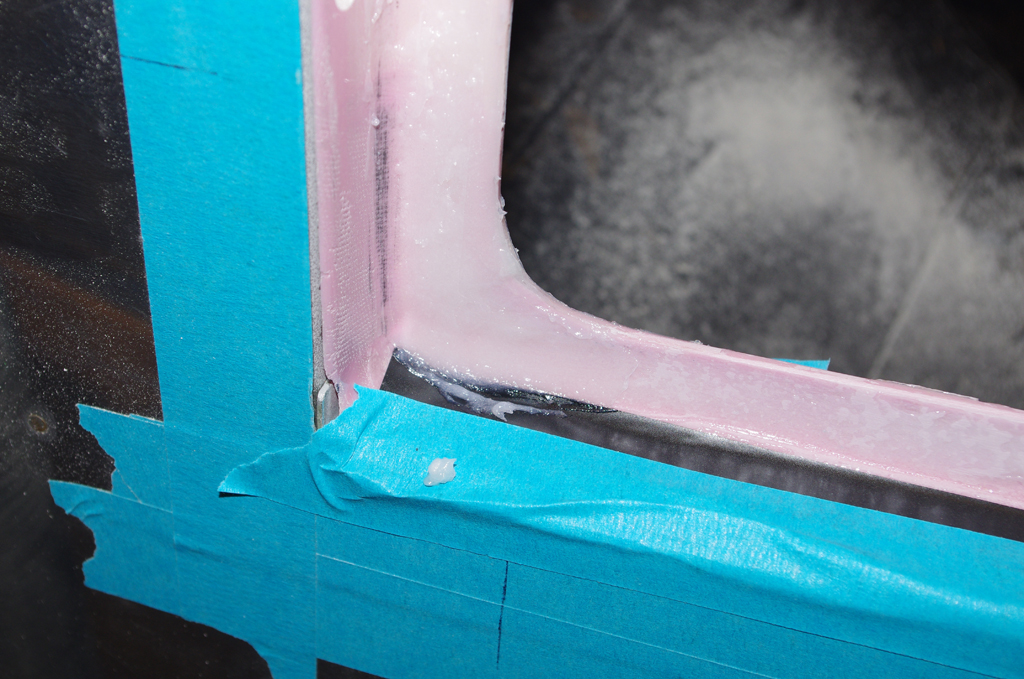
The slow process of applying filler and sanding on the doors, frames and canopy finally has an end in sight. Much of the time was preparing the door frame J-channel for accepting the McMaster-Carr weatherstrip molding. My intention was leave as much of the original canopy material in place as possible, just relieve enough for a good fit between the final lip and the door inner shell. In most cases this was sufficient, but on the lower door halves the default gap was wider than could be bridged by the weatherstrip. Here I opted to apply fiberglass/resin to build up the outer edges, then sand smooth and fit for a much better gap.
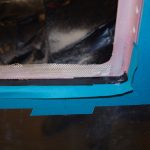
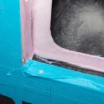 These photos show the lower left and right corners of the passenger door. This was the hardest area to build up. The default J-channel was very irregular, varied in thickness and sanding in the corners was difficult.
 After getting the doors to an intermediate fit, off came the doors and hinges. The intention is to send out the hinges for chrome. However, the steel finish as provided from Van’s is pitted or marred with milling marks. The portions which will be most visible after installation were hand sanded and polished. Hopefully this preparation step will lead to a better final look in chrome.
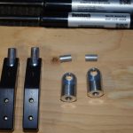
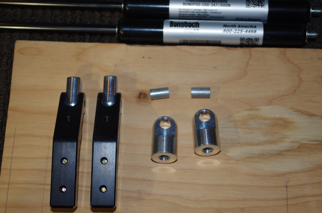
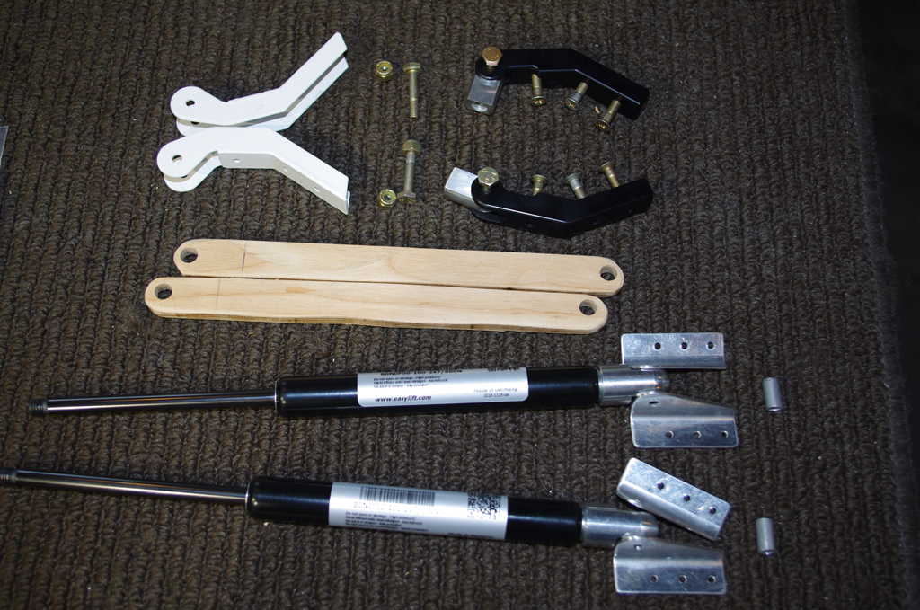
 Another set of fabricated items for the doors are hinge spacers for the Bansbach gas-struts, and bracket locating bars made from 3/8″ plywood. These bars will be used to properly set the distance from the AirWard strut brackets to the hinges on the inner door panel.
LATCH MECHANISMS
The exterior door handles provided by Van’s extend quite far from the door surface. After long deliberation I opted for the AeroSport low-profile handles. This requires modification of the latch pockets, but now is the perfect time as the doors are not finished anyway.
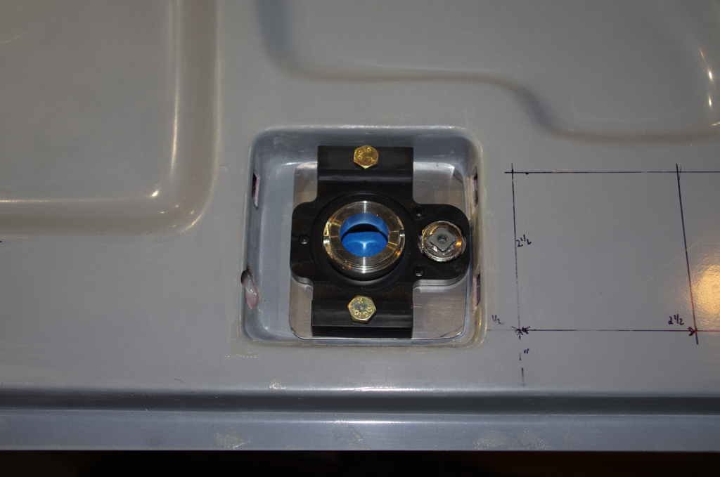
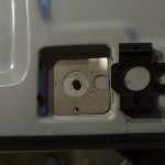 This photo shows a thin metal striker plate will be fabricated to accept the modified Delrin block to hold the standard latch gear and accommodates an integrated lock mechanism. This requires boring out a larger hole for the handle lever and a pass-through for the lock body.
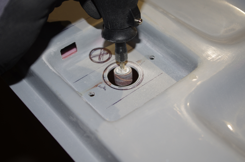
 The right photo shows the passenger door being modified for the larger lever body and lock hole.
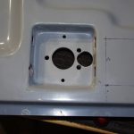 After the modification, the fiberglass around the lock is quit thin. Now I see why a plate of reinforcing steel is needed.
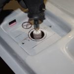
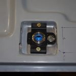 The lock does fit well, though maybe a lock with a shorter body would be better. Why – the Phillips screw holding the locking lever extends above the surface of the door interior. This would make fabricating a vanity or cover plate difficult.
AILERON PUSHRODS
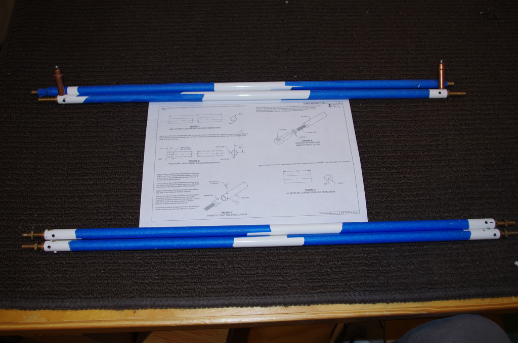
My first attempts at making the aileron pushrods did not turn out very well. So I reordered the parts and tried again…
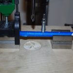
 This picture of the initial rods show how the rivet hole is chowdered badly from the drill press. The rod was not secured properly and moved drastically during the process. My bad. The rod was being held in a drill vise with the end sticking out, no support provided on the outer end to take the pressure and keep the rod from bending.
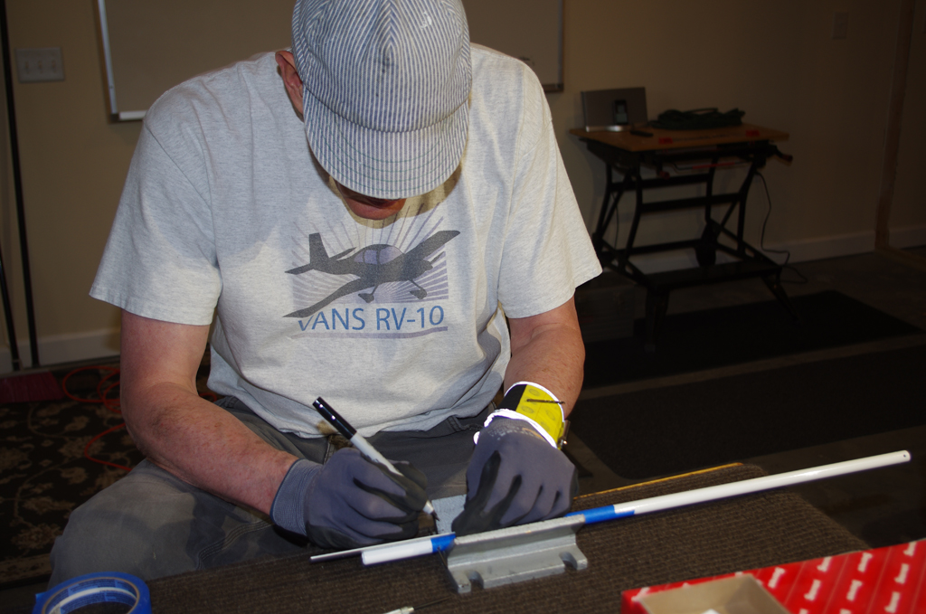
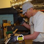
 At least two lessons were learned from the previous exercise: measure twice… and make sure the part is properly secured when drilling. In this photo shows measuring the 48″ rod to ensure there is sufficient room at the end to fit into a precision V-block on both sides of the drill location.
 After spot drilling (lesson 3 for small diameter rods, keeps the drill from wandering on initial contact) the separate inner holes are drilled. Note the V-blocks on each side. The rod was then cut in half and the two pushrods were adjusted by hand filing to 21 – 11/32″ length.
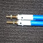
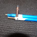
 The drill results are very good. The insides need to be primed, then all the through rivets will be inserted. The right photo shows a end of each rod with one rivet. Nice tight fit and no wiggle in the threaded ends.
 First steps are layout the pin guides on a sheet of .040″ aluminum. The designated 6.8degree angle supposedly compensates for the angled door frames. A protractor is used to get the angle close (only has degree increments).
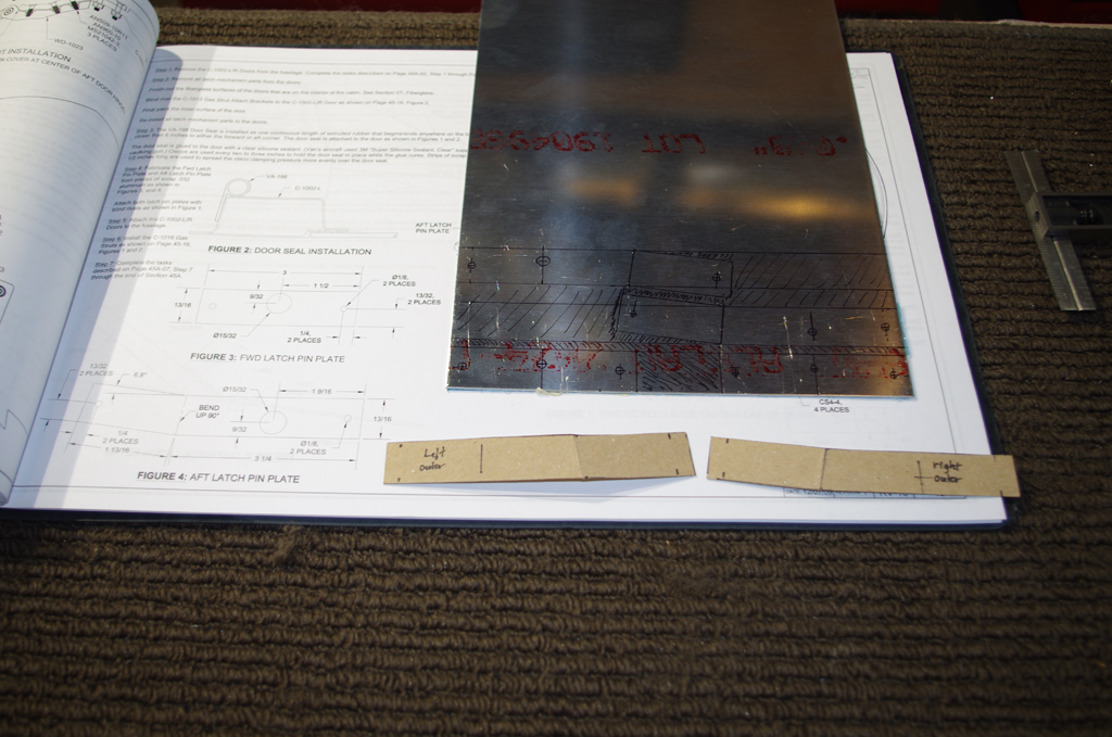 Stiff construction paper prototypes were cut prior to making any metal parts. I wanted to check the effect of the angles on the corners. Close enough for some hand shaping to be effective.
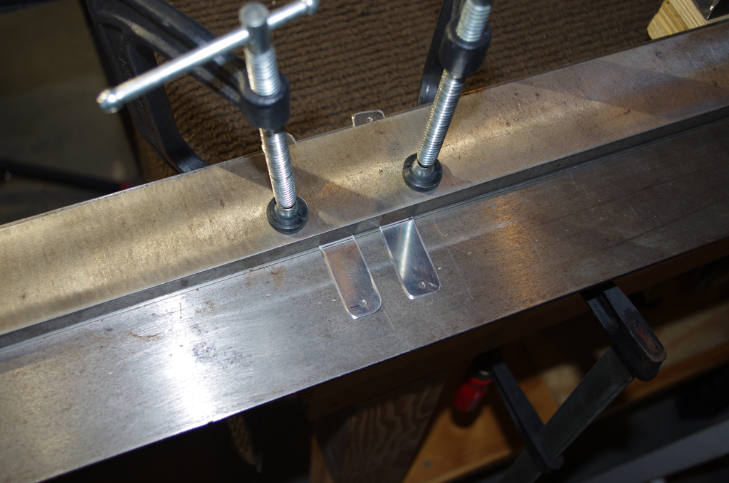 The roughed out pin guides are then inserted in Tal’s sheet metal bender and formed per plan instructions.
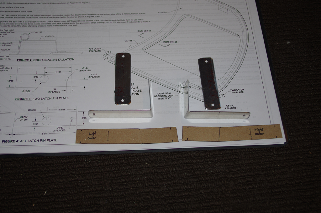 Here are the pin guides prior to fitting on the doors. Actual fitting required a bit of material removal. In retrospect I would first fit the pin guide hole from a slightly larger blank template, then shape down the attachment tabs to fit to the door geometry.
 Here are the raw and final fits on the passenger door aft guide. Getting the pin hole aligned properly took time with hand filing. The final gaps are good.
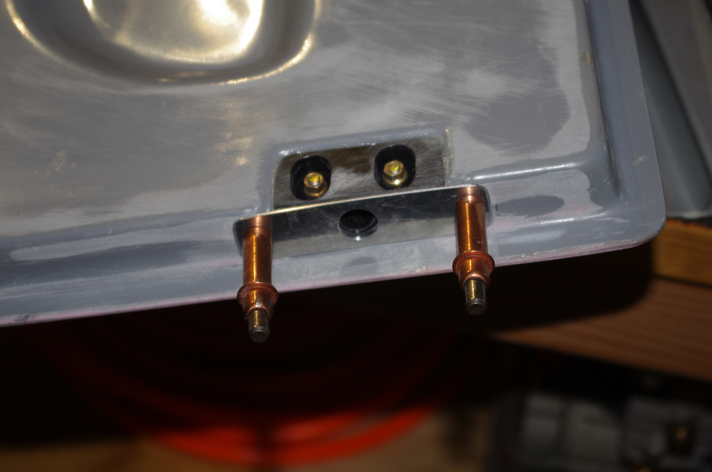 Here is a passenger door forward guide. Much easier since this is a straight piece. Now everything is ready for alodine/prime and covering the pin block with resin.