Monthly Archives: December 2015

You are browsing the site archives by month.

NAV Antenna Bracket

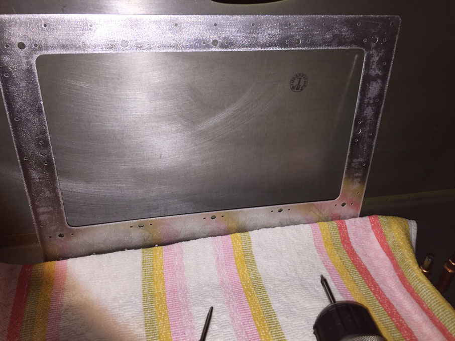
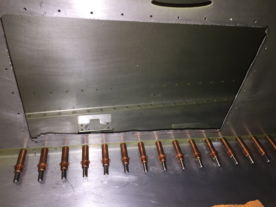
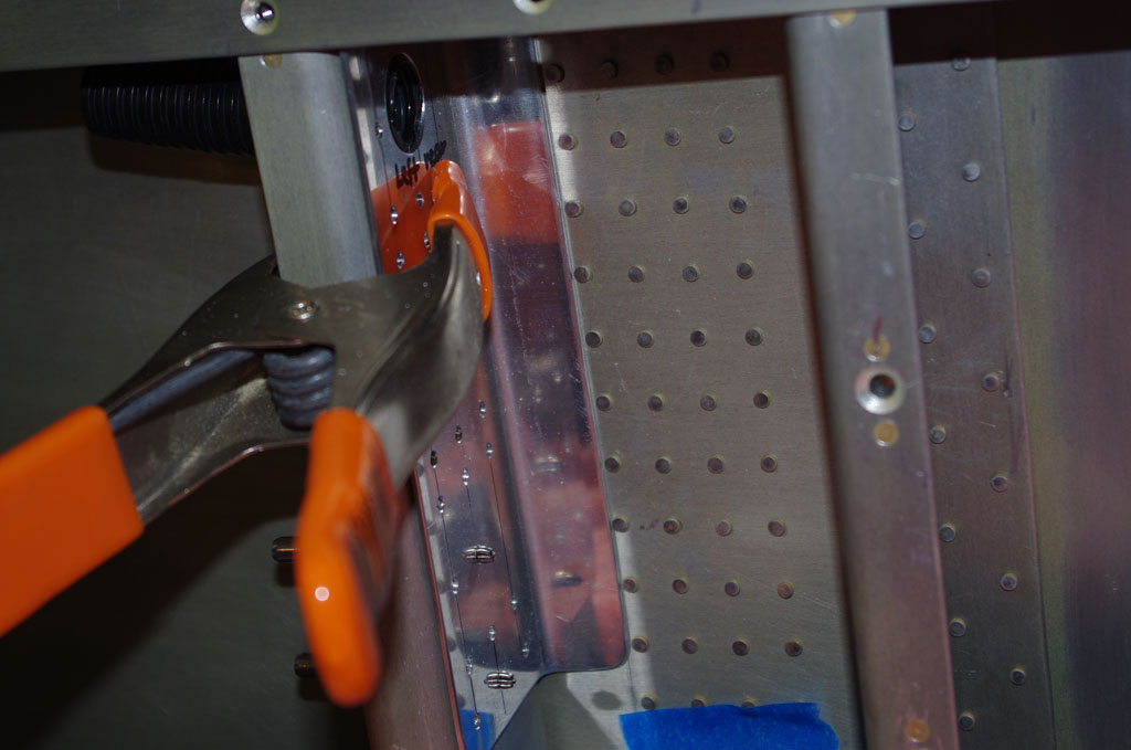
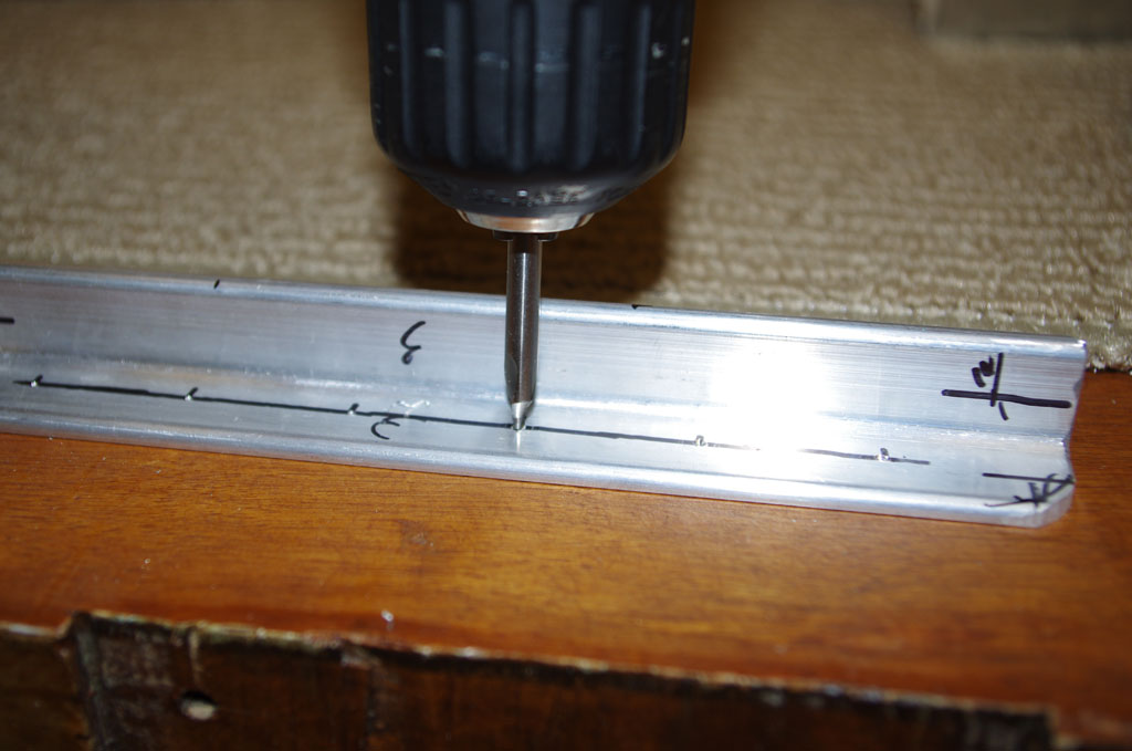
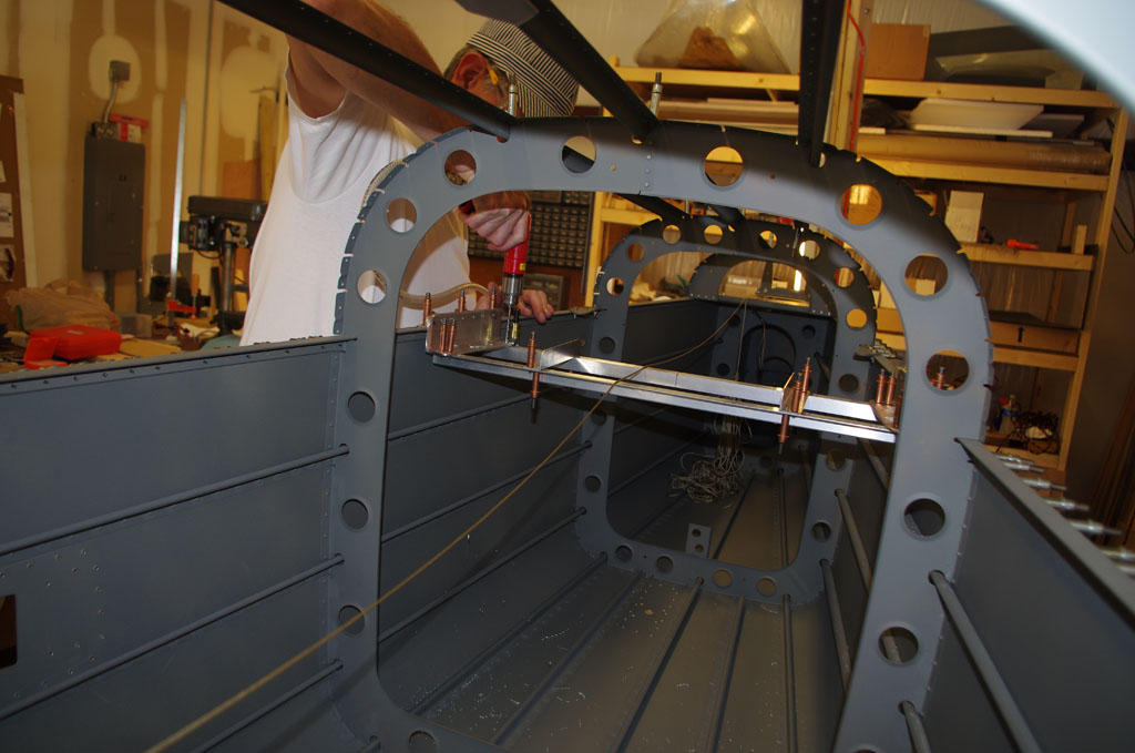
I started the day wanting to utilize the fantastic CherryMAX and CherryLOCK riveters loaned from my brother on the forward floor pans.  However, the offset head of the CherryMAX is rated for sizes 4,5 and 6 rivets, it does not want to work on generic LP4-4 rivets. The mechanism operates properly, just does not grip the smooth shafts of the generic rivets properly.  On test stock, a geniune CherryMAX rivet worked perfectly.  I may go out to Aircraft Spruce to purchase a few just for practice.

IMGP6024
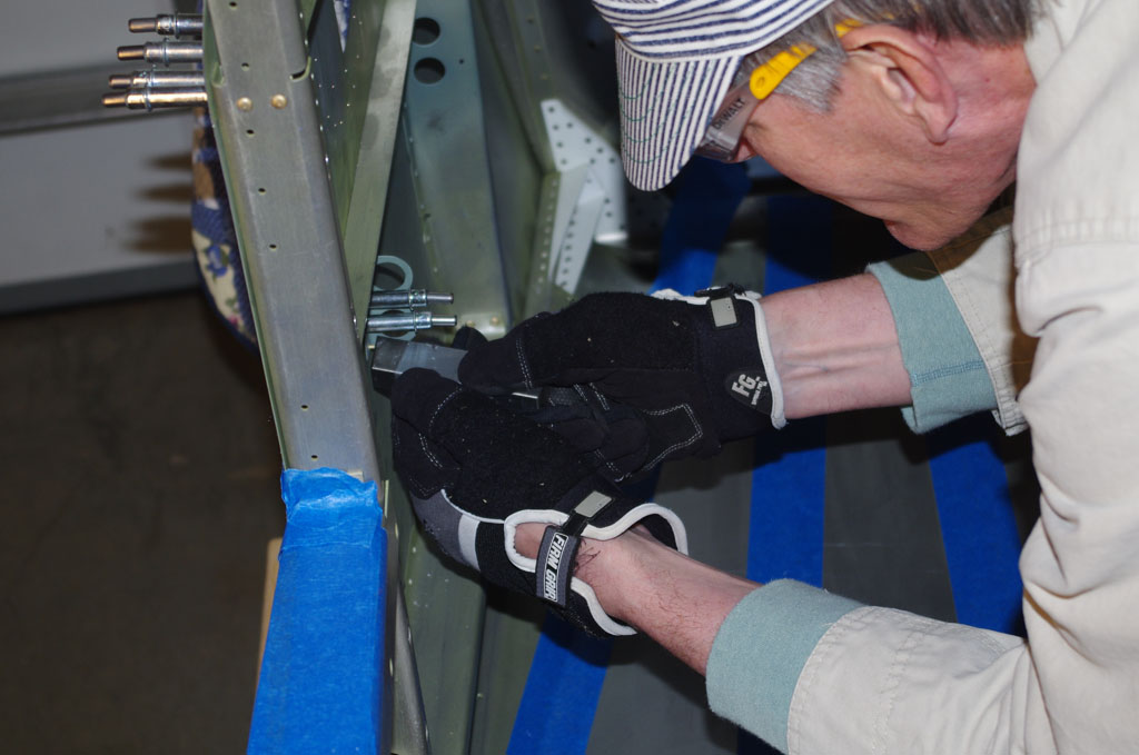
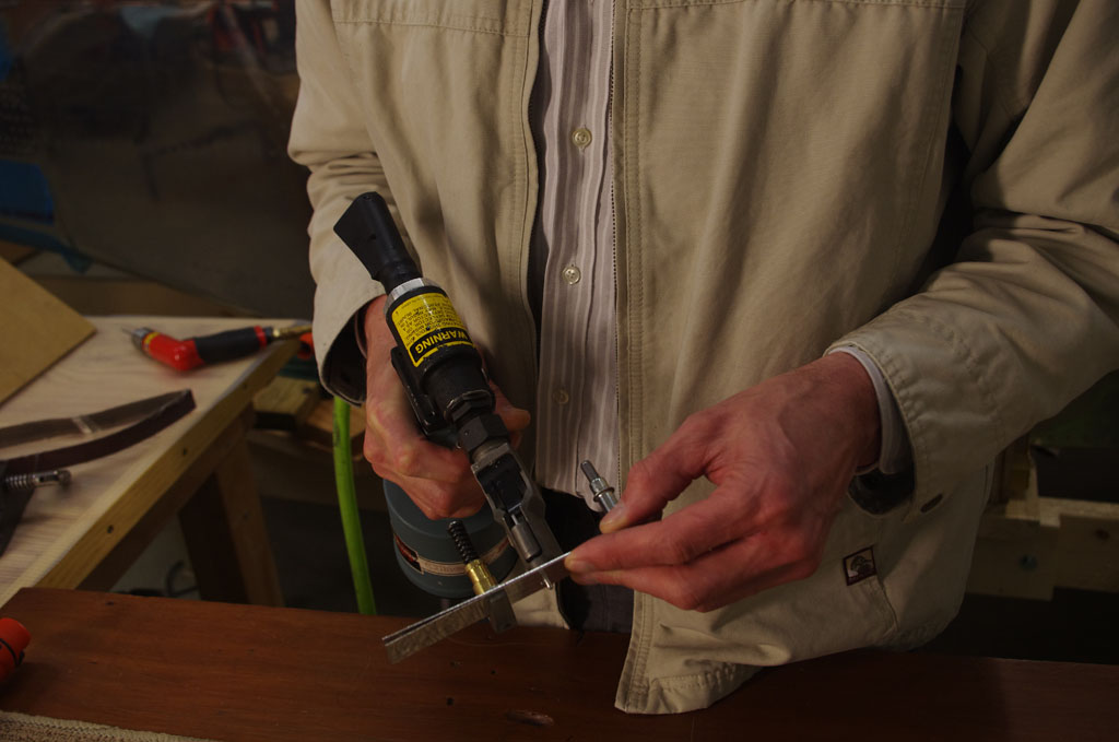
Here the CherryMAX rivet puller is attempted with an LP4-4 rivet.  No joy.


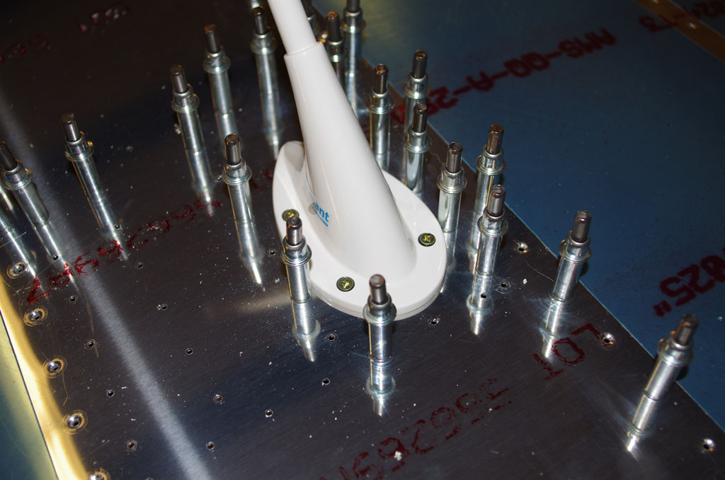
I then decided to start building a prototype bracket for the Comant CI-158C VOC/LOC/GS antenna.  The plan from way-back when building the vertical stabilizer (VS) was locate the antenna under the top fiberglass dome.  I had previously added a 5/8″ black conduit and reinforcing plate to this location on the VS.  Now the antenna puck and whip antennas are physically available for inspection, I probably would relocate some of the holes to make assembly easier. Anyway the mock-up was started with a piece of 3/4″ red oak to simulate the eventual stock of acetal copolymer (ordered today).  The DuPont trademarked material is called Delrin, and differs from the generic acetal by consisting of a monopolymer – somewhat stronger, but considerable more expensive.  I had originally thought of using a nylon block, but my technical counselor advised against due to the greater mechanical properties and ability to machine finish the copolymer.

IMGP6028
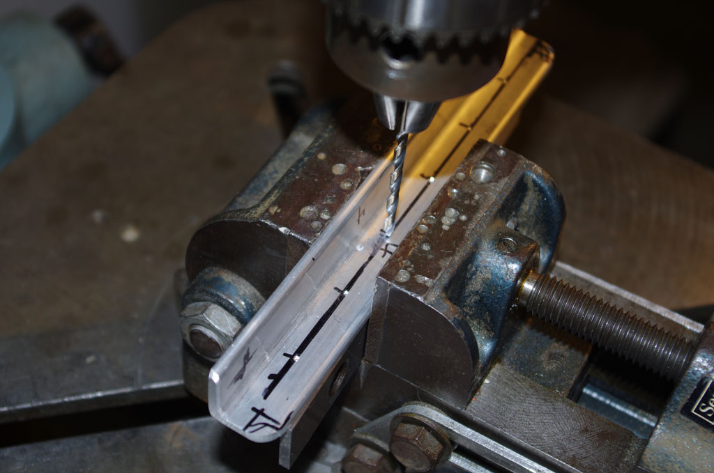
Here the oak board is clamped in the drill press for side drilling a 1/2″ hole. My thought is use an aluminum rod to hold the stainless whip antennas, then secure with a set screw performing double duty as the electrical connection to the integrated puck/balun.


IMGP6030
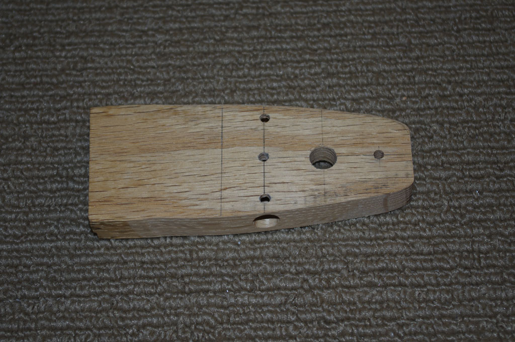
All the main holes are drilled. The final acetal block will have the set screw location tapped for a #10-32 stainless screw.


IMGP6033
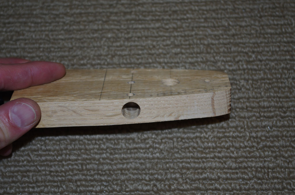
Side view of the raw block.  Sanding and fitting inside the upper cavity is next.


IMG_0106IMG_0107
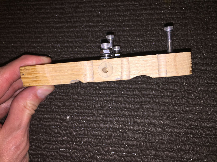
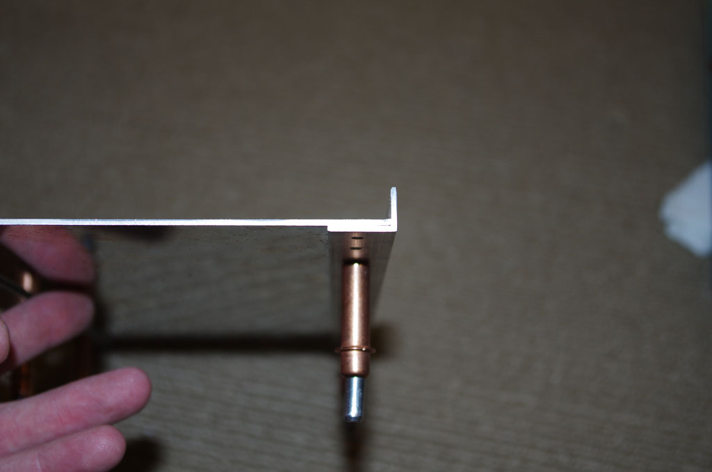
Side view of the fitted block, with mounting and set screws in position.  The right photo has the stainless antenna provisionally fit into a 1/2″ wooden dowel.  This matches the final use of a drilled aluminum rod to hold the antenna.


At this point the prototype is done – just need to smooth out the lines and measure everything for when the acetal arrives.

IMG_0109
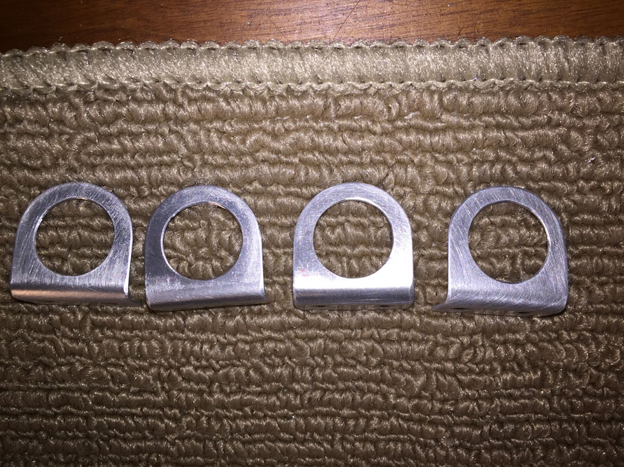
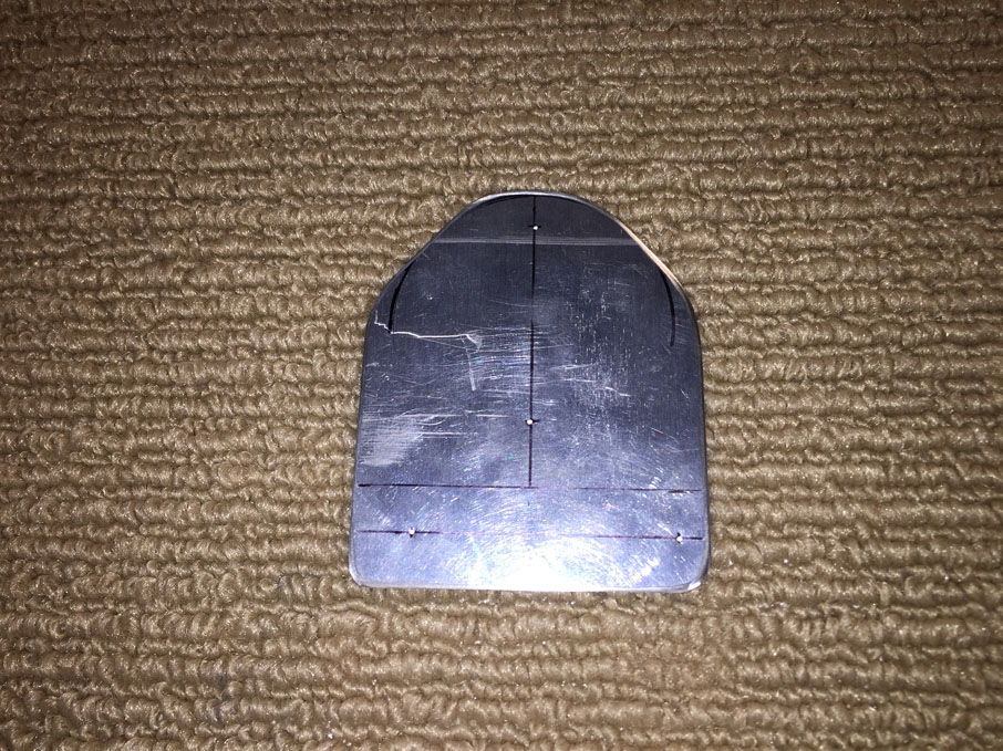
Here is the raw puck bracket.


IMG_0110IMG_0113
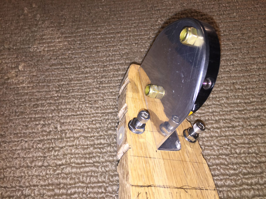
Left and right views of the puck bracket on the oak antenna prototype.


F:FaustRV10-N190XBWireDiagramsVOR-Bracket-v04.dwg
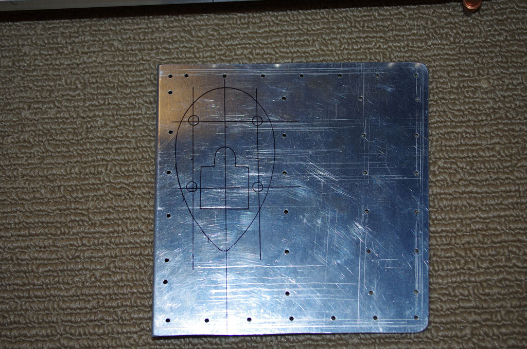
After building the prototype, I laid out a rough diagram of the final product. I never had any drafting skills, but the outcome should be understandable.


Forward Wire Covers

After purchasing the latest RV10 plans CD now available from Van’s, I noticed they have an optional wire covering from the spar bulkheads to the instrument sub-panel.  This part only cost $14, so one was purchased and fitted on the left side.  I like the appearance so well, the left side will be used to build a mirror image for the right.  Adding two upper holes provides four different wiring pathways to the firewall or instrument panel – two above now being created and two 5/8″ black plastic conduits under the forward floor panels. This same configuration will be on both left and right sides and should provide more than adequate wire routes to the wings and tail.

IMG_0097The first step is layout the hole drilling pattern as per the installation instructions.


IMG_0098Drill out the holes to 3/4″ diameter using a Unibit. The angle was a bit tight for the cordless drill, but the results after SEM self-etch priming look good.  I have decided not to fully alodine/prime attachable parts in the cockpit as exposure to elements like in the tail should be reduced.


IMG_0101Here the F-1016H brackets are prepped for priming.  These will hold SB750-10 black plastic bushings for the wire runs.


IMG_0102The holes for the brakets are match drilled through the forward skin under the NACA vents.  After dimpling, the brackets are ready for AN426AD3-3.5 rivets. Note new bushing holes on the right side of the plane are also visible.


JANUARY 6, 2016

Eric and I riveted the dimpled and SEM primed brackets into place.

IMGP6036 IMGP6038

Once again, climbing inside the unfinished cockpit to buck the rivets is a bit cramped.  Eric outside could drive with ease.


IMGP6041IMGP6043Here is the final view of the right brackets, inside and from the outside.


Tunnel Inspection Plate

I bought an inspection plate from AirWard for later inspection of the boost pump and central tunnel wiring.  The installation of the backer and plate is fairly straightforward, but getting a comfortable position to work on the QuickBuild kit is not easy.

IMG_0086Here the backer is placed beside the tunnel for initial fitting and drilling.


IMG_0088Here all the rivet holes are match drilled with the tunnel wall.


IMG_0089The cover plate is clecoed into position to mark the edges for cutting out the hole.


IMG_0092I used a nibbler to rough out the inspection hole using the same technique as for the NACA vents.  Some people use a sabre saw or similar mechanical device, but I seem to get in trouble quickly with such devices.  The hand method is very much slower, but I have better control and fairly good results so far.


IMG_0095IMG_0096

The left photo shows the nibbled inspection hole. The right shows the top and left sides rough filed into shape.  Tomorrow I hope to finish off the rough shaping, then do final smoothing and fitting.


DECEMBER 26

IMGP5935Kneeling in the cabin to hand file the edges took a few hours to complete.


IMGP5941IMGP6001Final fitting on the inspection plate, then SEM prime the tunnel opening.


IMGP6004IMGP6003Retaining bracket front and rear after SEM priming and nut plates installed.


IMGP6009IMGP6023Bracket clecoed in position, the final rivets installed.


COM2 Antenna Plate

The original stringer reinforcement plate I made to secure the air supply valve did not turn out as well as hoped.  I decided to rebuild this and combine with a backing plate for the COM2 antenna to be located in the upper section of the tailcone, just behind the baggage bulkhead.

IMGP5918The plate will span between the center stiffener and the one on the right side.  The left edge was bent on Tal’s brake to match the J-channel profile to provide added strength to both the left stiffener and the backing plate.  Here the plate is measured and drilled for rivets.


IMGP5924

This photo shows the plate fitted into position under the tailcone skin and beside the center stiffener.  Note the angled bend in the backing plate as mentioned earlier.


IMGP5926IMGP5928

Once all the rivet hole were match drilled and the plate securely clecoed into position, it was time to use a Unibit to fashion a 9/16″ inch hole for the antenna BNC connector.


IMGP5932Here the antenna is provisionally fitted to the skin.  Everything lines up nicely!  The final installation will  have a thin cork gasket under the antenna base and above the skin.


IMGP5933Here is the final plate before dimpling, alodine and prime.


Spar Reinforcement Brackets

The fuselage quickbuild kit comes from Van’s with only two 5/8″ ID holes for cable/wire runs over the main spars.  This was probably okay 10 years ago when steam gauges still ruled, but my intention is for a nearly all glass cockpit with a dual battery, dual alternator system for maximum reliability on the electrical system.  This means running way more wires between the instrument panel / firewall and the batteries located behind the baggage bulkhead.

As a result, I will be adding two additional holes in the spar brackets and will need to reinforce these holes with .063 backing plates custom fabricated for the task.

IMGP5904Notice the top left hole – this is actually the lower of the two factory provided holes.  It will be used as the starting point for the two new holes which will be drilled lower on the spar brackets.  The rear bracket is 2.25″ wide, the forward bracket is 2.0″ wide.  Not sure why, but that’s the way they are.


IMGP5907Here are the rear bracket plates (left and right) after the new holes have been drilled.  The reinforcing rivet pattern and spacing was derived from sketches in the AC43-13 document.


IMGP5909IMGP5912Two different views of the spar brackets after being match drilled with the plates.  Next steps are alodine and prime the backing plates before riveting in position.


AHARS Platform

The Thanksgiving week was used to prepare an adjustable platform for two remote AHARS units.  My current plans are to the Dynon products for most of the avionics.  Dynon calls for the platform to be within one (1) degree of the centerline and one (1) degree from the horizontal level.  The centerline issue should be relative straightforward, but the horizontal can only be determined accurately after the plane is flying.  As a result, the adjustable table would make later configuration much easier.

IMGP5856First is layout the basic parts after measuring, cutting, sanding, and scotchbrite.


IMGP5852IMGP5855Next is center punch, center drill and initial drill on the drill press using a floating press vice.


IMGP5861IMGP5867Here the .063 table sheet is match drilled to reinforcing brackets.  The intention is have long #6 brass screws in the four corners with aluminum washers as spacers to achieve the final one degree angle.


IMGP5889Match drill the side brackets to the tailcone longerons.


IMGP5894IMGP5896The 2mm paracord down the centerline of the plane is used to properly position the AHARS frame.


IMGP5899IMGP5898Match drill and cleco the frame to the side brackets.


IMGP5895IMGP5900And finally… align the adjustable table with the centerline and mark for drilling the brass screw holes.  I will do this later on the drill press to get a good perpendicular hole between the table and the frame.  The final spacing washers will be installed once the AHARS remote units are purchased and their table mounting holes are drilled.