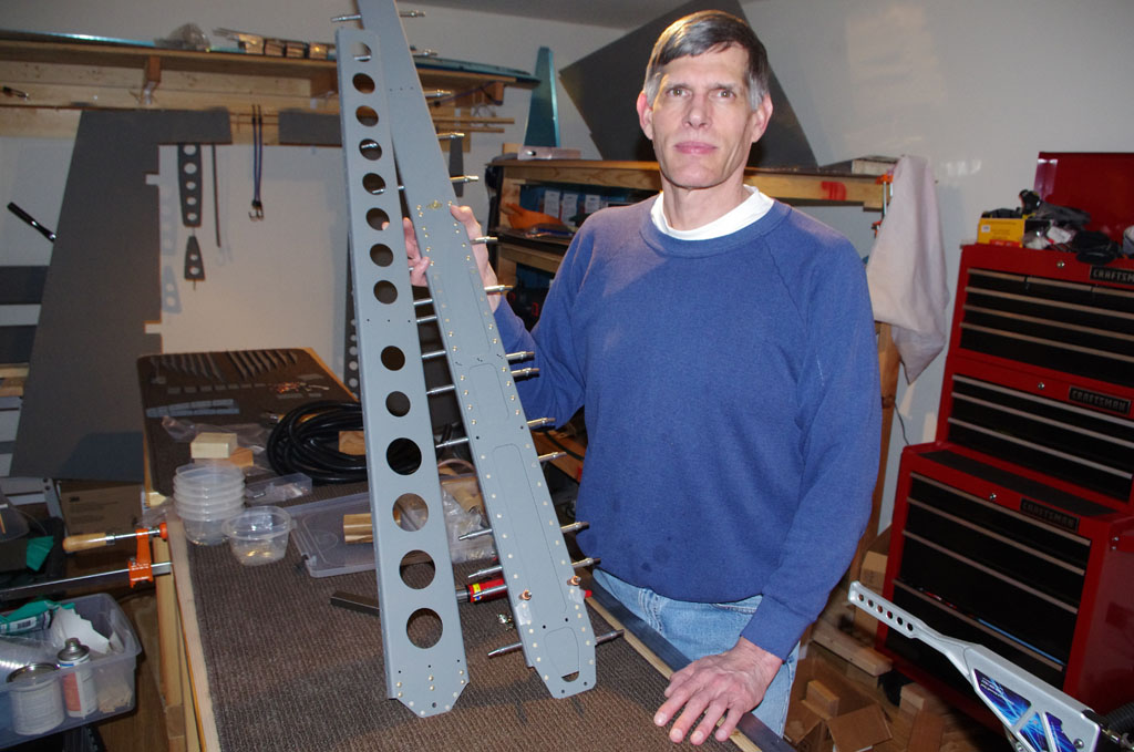
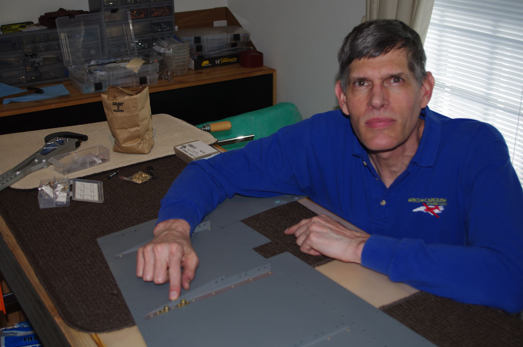
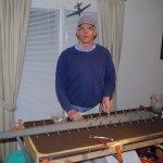
Another power weekend with Rich and the vertical stabilizer is assembled! After months of metal preparation, logistics and practice on sacrificial mini-projects, the big day for actually setting rivets in plane parts was upon me. In the lead up week, my technical counselor (Terry Gardner) came by to evaluate progress and provide final tips. With a bit of trepidation and rivet gun in hand, it was time to pucker and pull the trigger…
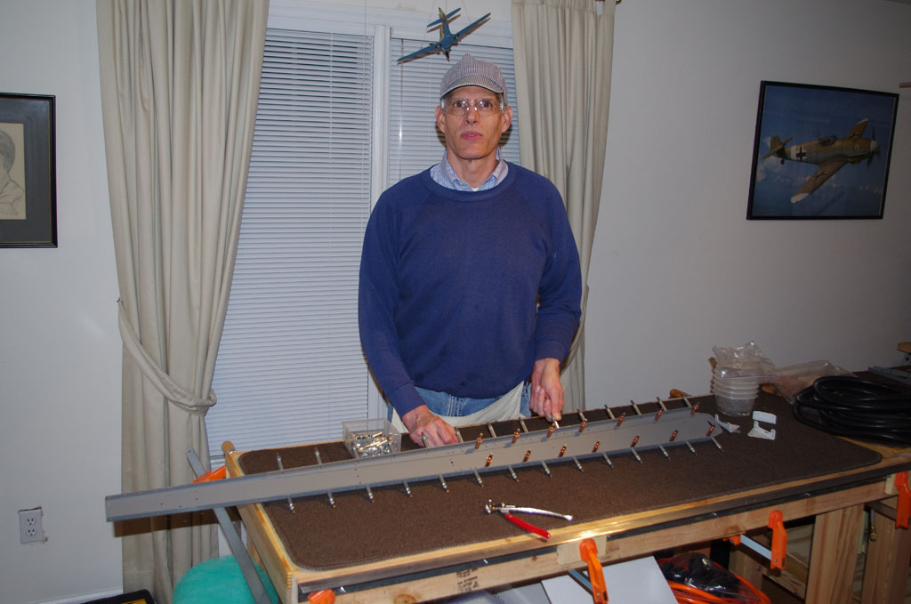
Thursday evening the VS spar was assembled. The spar, spar caps, doublers, and rudder hinges were all squeezed. No worries here and the results were good.
No drill outs or smileys on the final spar assemblies.
Rich and I made extensive use of a Van’s mini-wing project to practice the rivet/bucking techniques needed for most of the work on skins. Good thing too, because our initial efforts were miserable. The greatest damage was done when the tungsten bucking bar slid off the rivet, pounding the h*** out of the skin from the inside. Many adjustments to the air pressure at the rivet gun were also needed to get things into a calmer, but effective range.
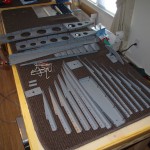
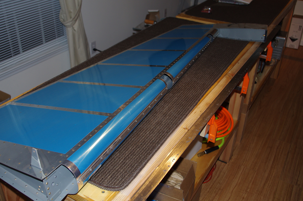
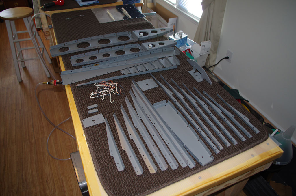
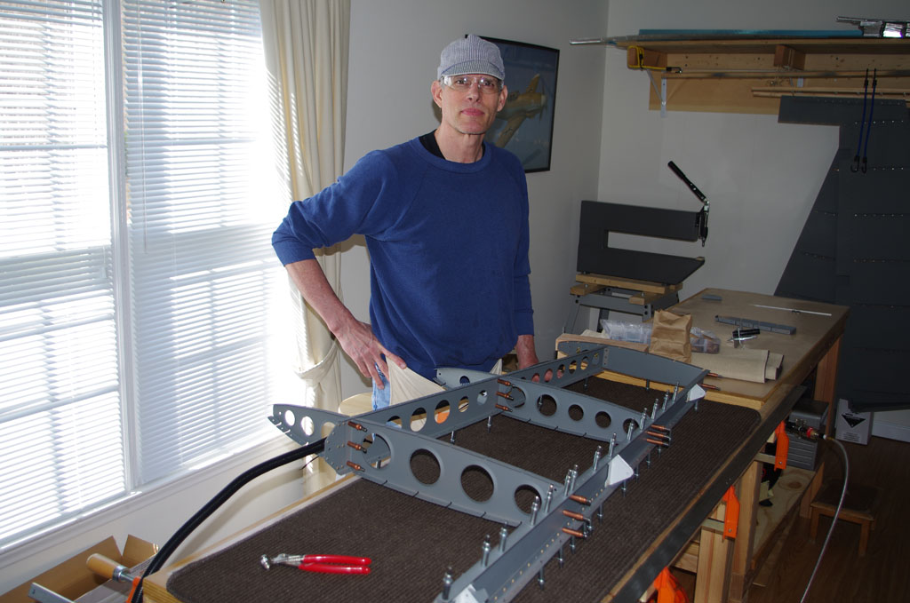
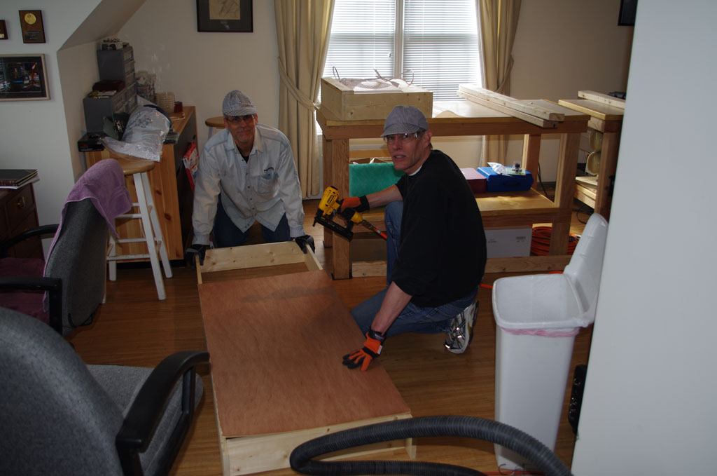
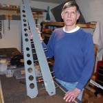
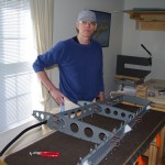
I took a day off work to take advantage of Rich’s final days on his visit from Texas. This picture shows the parts staged on Friday morning for both vertical stabilizer and the rudder. The plan was squeeze, back rivet, then buck as many parts in that order. First priority was completing the VS over the weekend, nice to have the rudder done if possible.
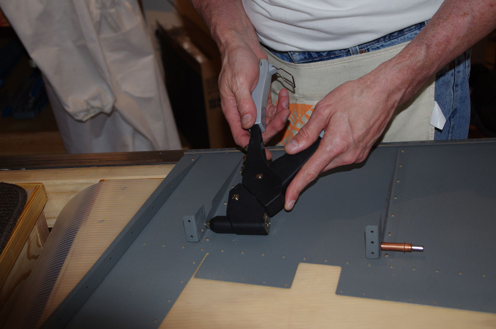
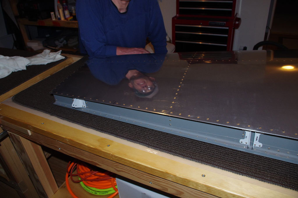
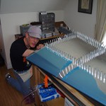
Back riveting the rudder skins. This was obviously not part of the VS build, but I wanted to save bucking activities until last.
Again no problem. The back rivet results are all good.
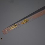
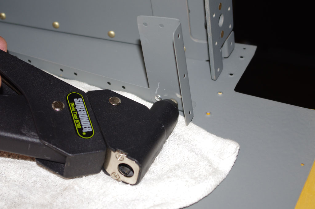
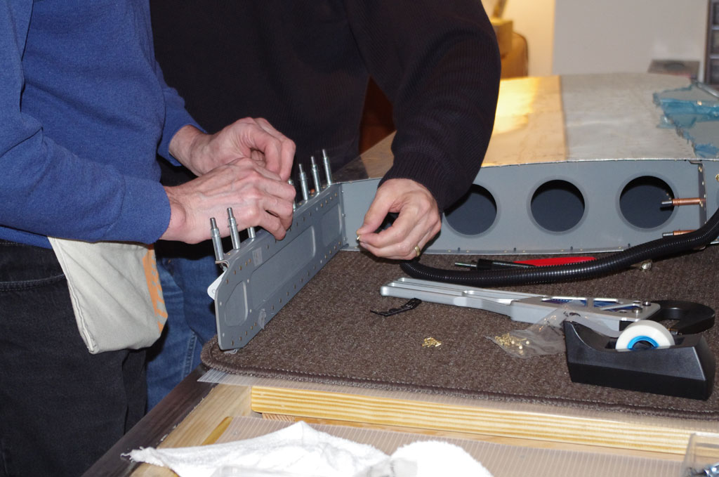
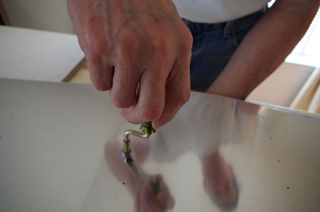
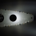
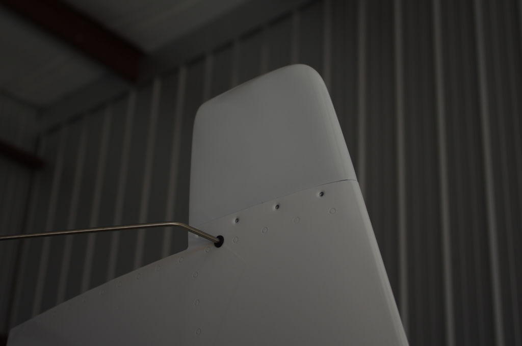
Here is the final assembly of the static wick nut plates.
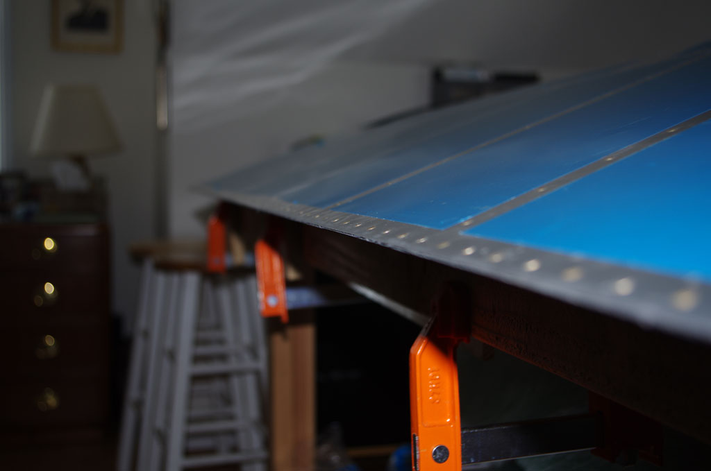
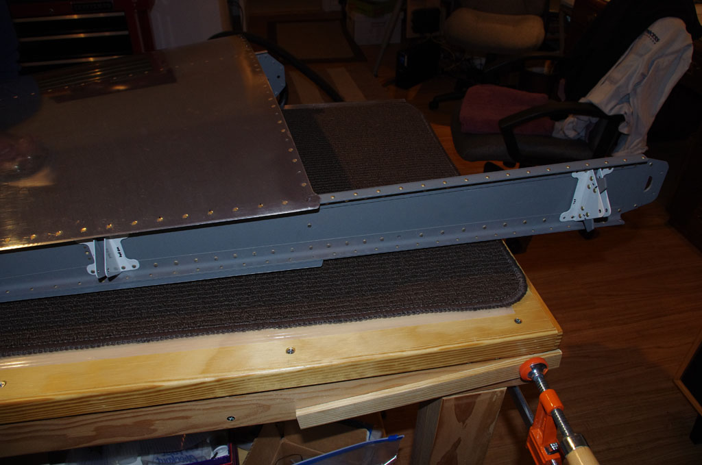
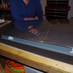
Staging the VS frame for squeezing.
Notice the flexible conduit running through the forward rib lightning holes. My custom rib doubler and the lightning hole wire ties for holding the conduit worked like a charm.
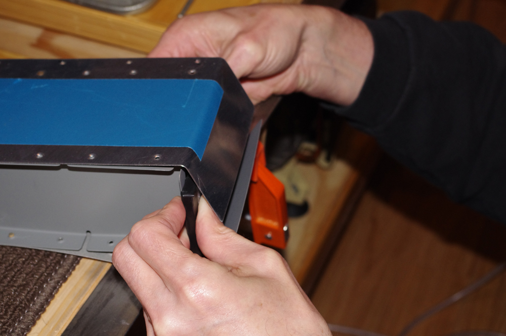
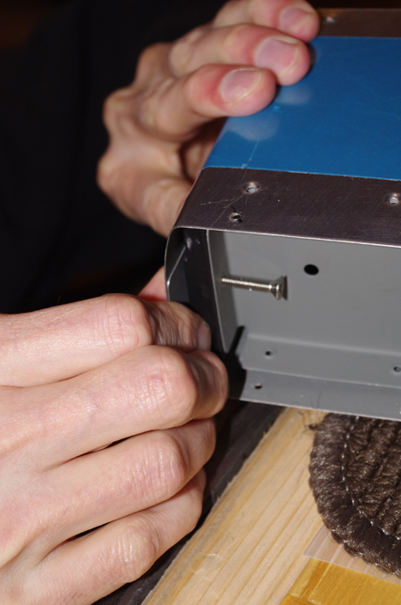
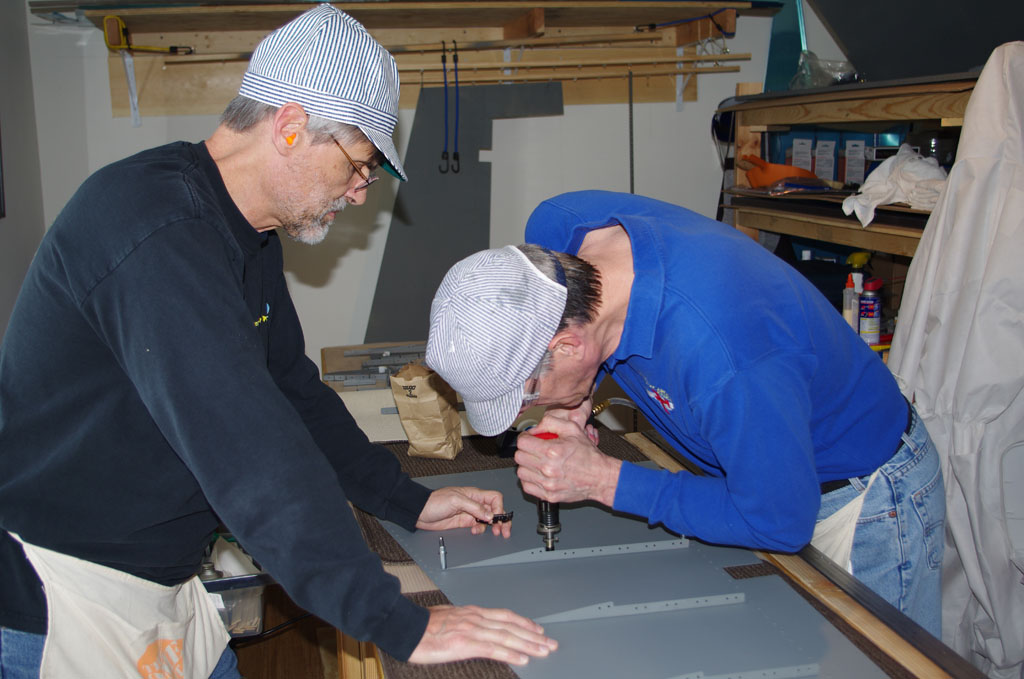
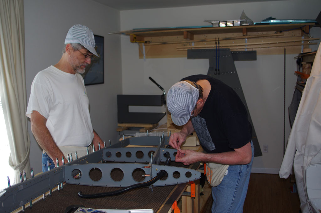
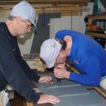
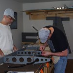
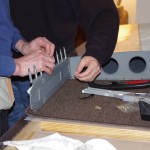
Okay, here is where a serious case of nerves set in! Our first ‘production’ bucking experience was on the middle nose ribs. I had to reach a full arm length into the skin cavity to hold the 1.7lb tungsten bucking bar up against an AN426AD3-3.5 rivet. Other builders have seriously disfigured the skins in this section; this being one of the most difficult assignments on the whole plane build right at the beginning. At this point I was very anxious and the pucker-factor quite large.
This picture is fuzzy, but does show the finished rivets on the middle nose ribs. I had to go through some contortions, but eventually was able to see the rivet/bar with a flashlight during the bucking operation. Seeing the rivet shank and not being blind made all the difference. Added to this, Rich did excellent work driving the rivets with a steady hand and consistent manner. I was quite pleased with the resulting shop heads.
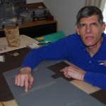
Finishing up the lower spar and spar cap squeezes. The overall assembly process went slower than expected, but we were very deliberable on purpose.
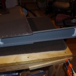
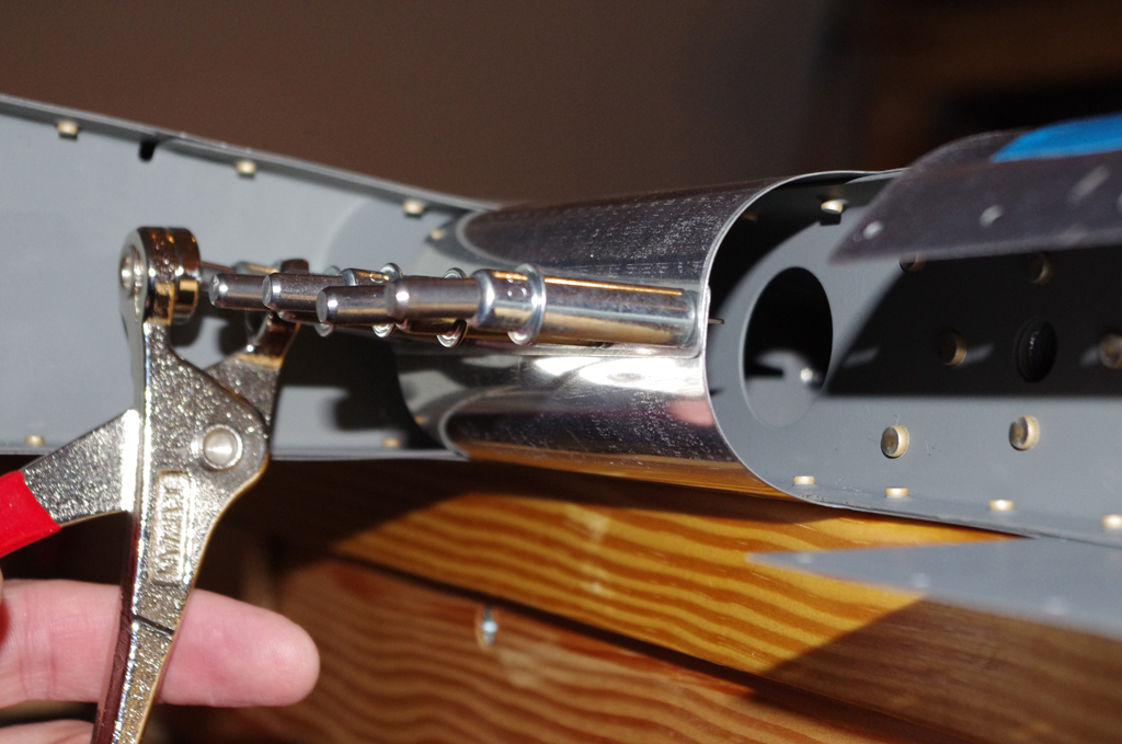
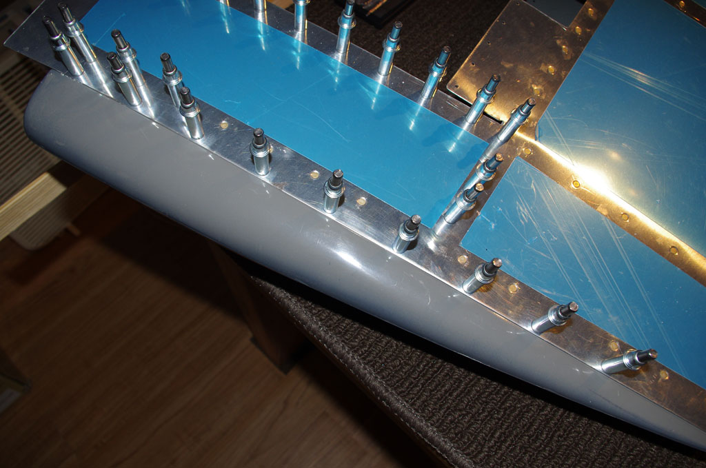
Final result on the lower part of spar. We used a 1.5″ diameter mushroom rivet set with a rubber apron for the skins. The rubber apron kept the rivet set from bouncing sideways and cushioned the impact to some degree.
Final result on the upper part of spar. We made sure to use rivet tape on every single flush rivet. This small, but important step keeps the head from crushing off all corrosion protection on the rivet set or die, but also prevents the skins from getting scratched.
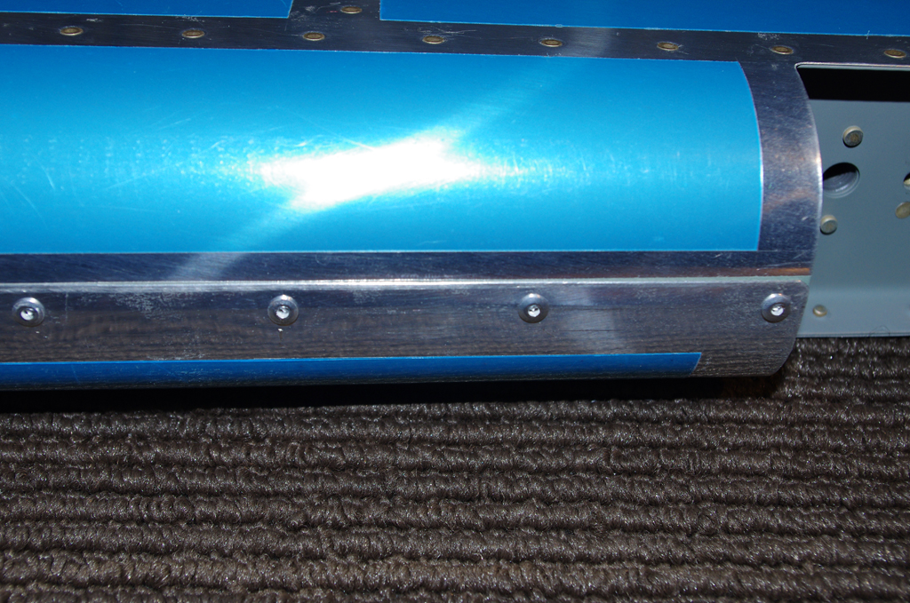
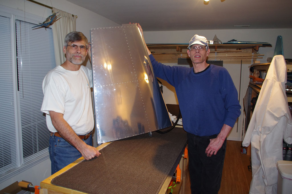
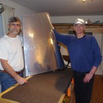 Saturday evening saw happy campers and great results! In the end we only had to drill out 3 rivets. Interestingly enough all three of these were squeezed. No smileys or dents in the smooth skin surface are also testimony to careful planning and solid execution. Who would have thunk it given my previous concerns about bucking.
I could not have achieved this excellent outcome without Rich’s help.
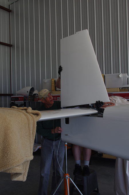 Here the vertical stabilizer was being attached to the empennage – hopefully for the last time.
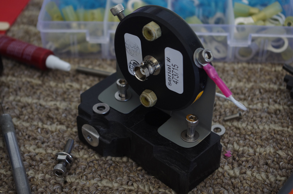
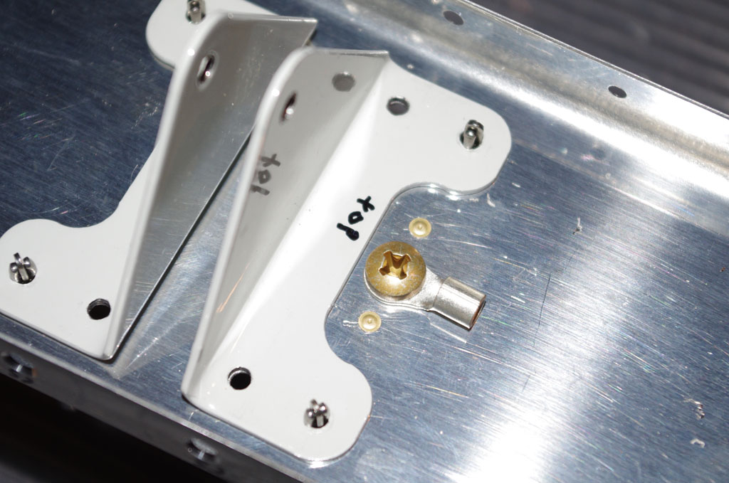
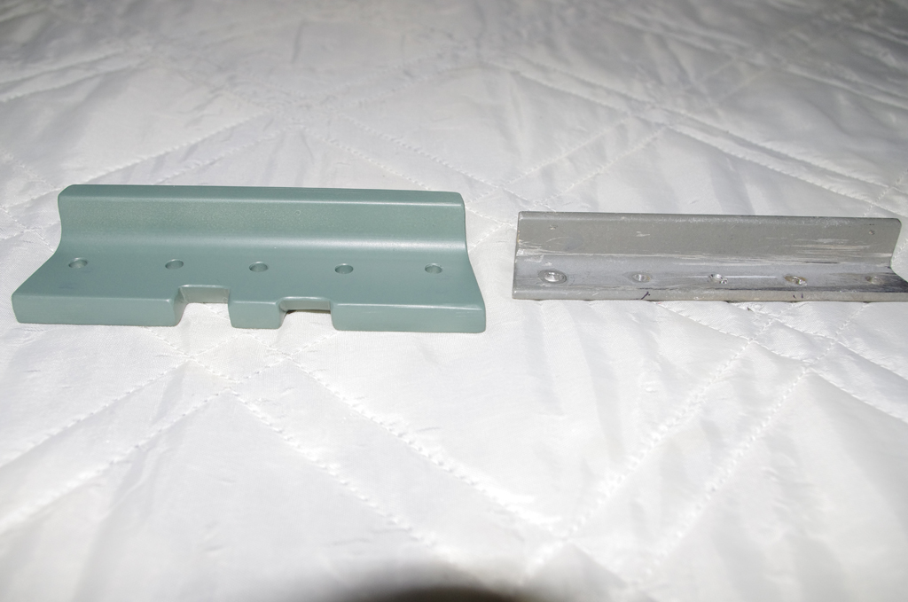
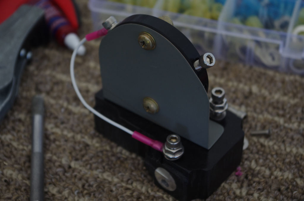 I made this custom NAV antenna bracket many moons ago. In retrospect, I would probably forgo this bracket and mount the antenna directly under the fuselage.
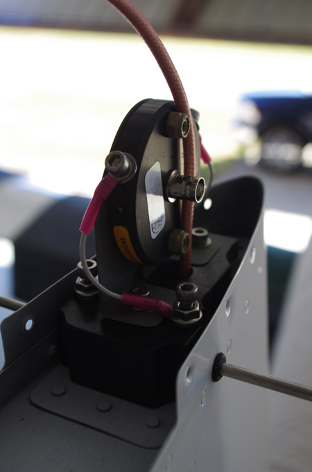
 Anyway – here was the final connection and covering by the VS cap.
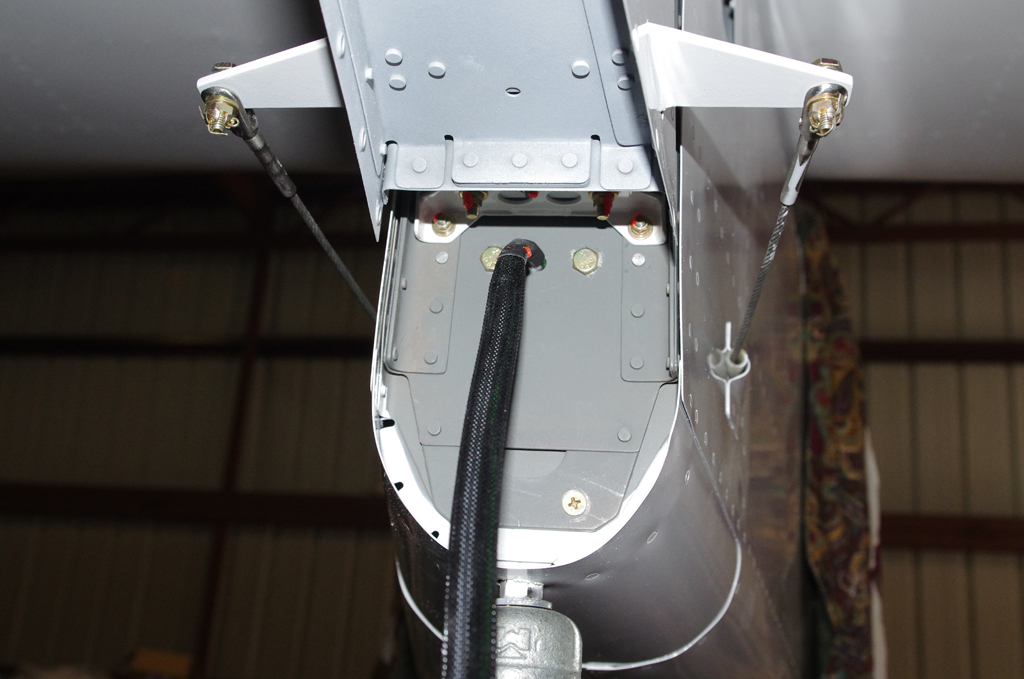
 The left photo shows the Suntail Strobe/Nav wiring exit between the rear fuselage and the rudder bottom. On the right is the original elevator stop replaced with a much heavier and larger alternate means to comply with Service Bulletin SB18-03-30 from Vans. This modification prevents over-rotation of UP elevator.
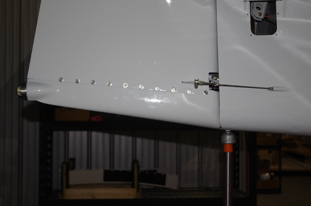
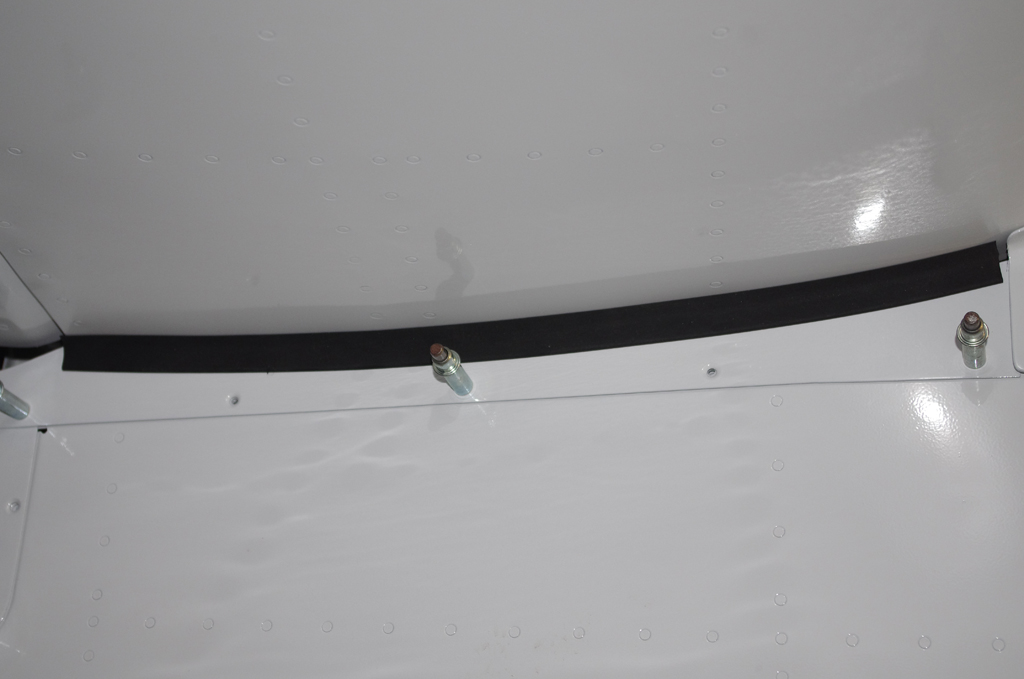 Following attachment of the rudder bottom, intersection fairings around the VS and HS were installed. Thin rubber edging protects the HS paint from the elevator trim covering. Note the elevator horn to elevator push rod assembly in the upper right of the first photo.
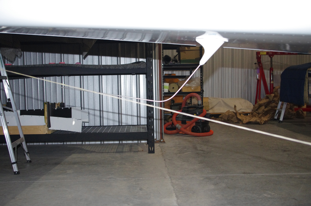 This photo shows a taut line extending from the main wheels at ground level to the rear tie down point. This confirms the COM1 antenna will not scrape on the runway during takeoffs or landings.
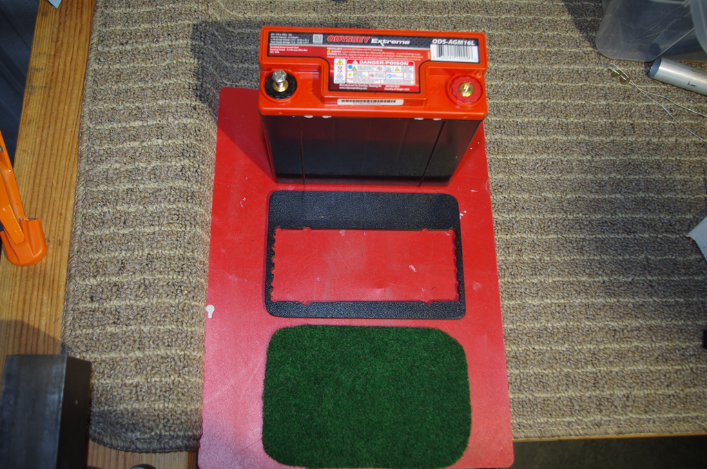
 The Odessey 680 batteries were secured with a Delrin-like polymer frame with a felt underlayment for protection. Here are the components before assembly.
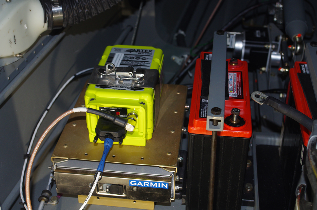
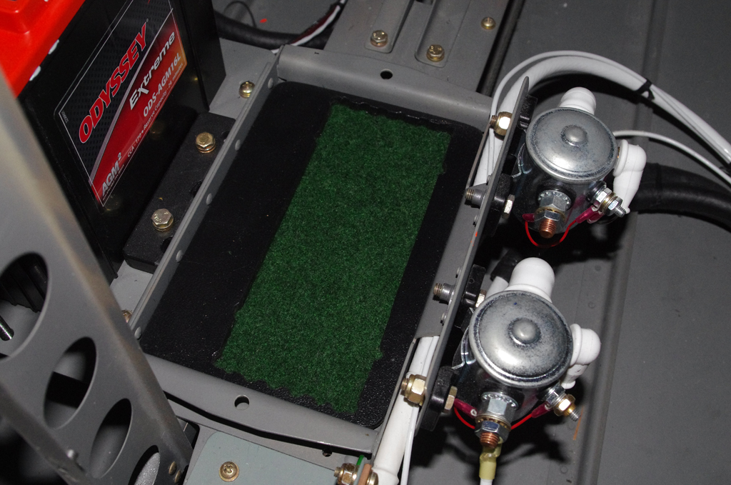
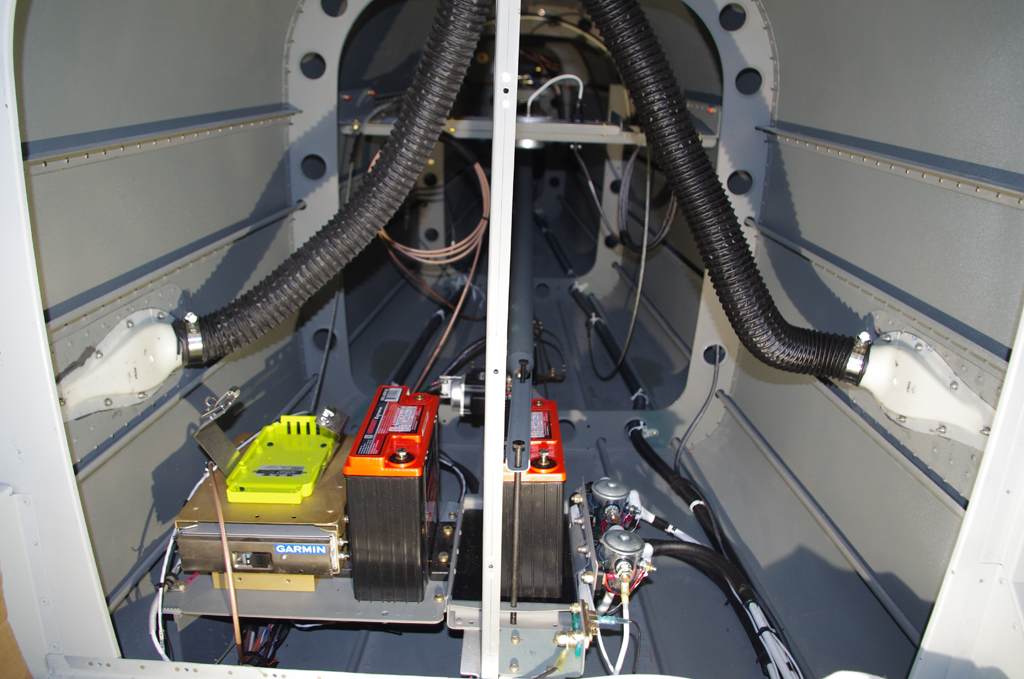 The final configurations of the battery boxes, Artex 1000 ELT, and the Garmin GTX45R transponder/ADSB behind the baggage bulkhead is show here.