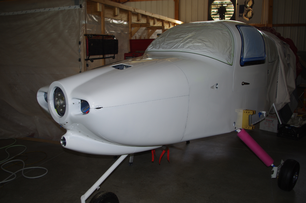
Although I have not posted in quite some time, work has continued on the airplane. Primary attention has been given to cowl preparation and engine baffling.
 The propeller used for the aircraft will be a Hartzell HC-C3Y1R-1N/N7605C three composite blade, hydraulically controlled model. The recommended gap distance between the rear of the spinner and the forward face of the cowl is to be no greater than 1/8″ to 1/4″.
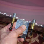
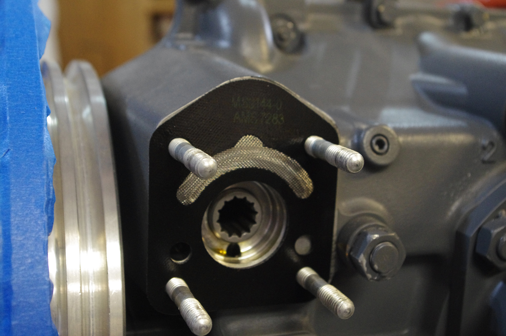
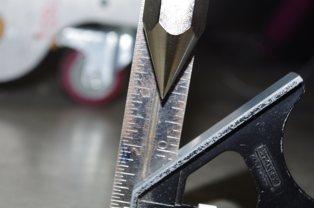
 The propeller hub measures 2.5″ from the forward face of the flywheel to the rear face hub bolting location of the spinner retention flange. The flange spacers are 1/4″ long, the flange itself is 1″ wide, and finally the 1/4″ gap between spinner and cowl means the distance from flywheel face to cowl front should be 1″ apart. Fine adjustments up to about 1/8″ can be made to the final gap by shimming the spinner flange with washers.

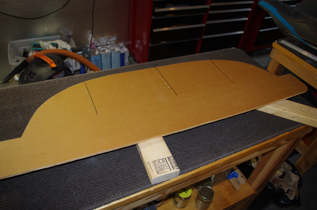
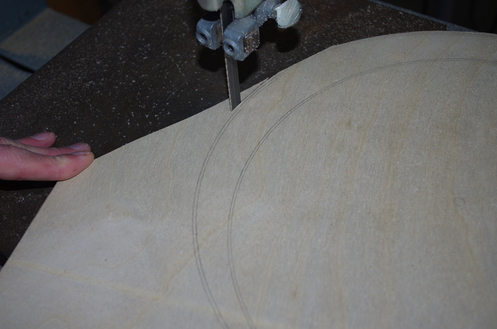
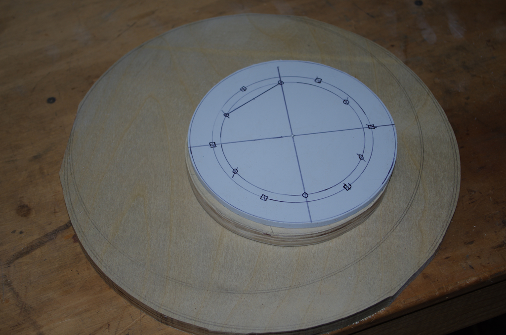
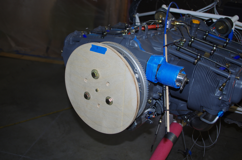
 The cowl gap distance seemed difficult to measure accurately without a clearly fixed reference point. I decided to use the face of the flywheel as the starting point for all measurements. Here a plywood disc is measured and cut to match the spinner diameter.
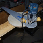
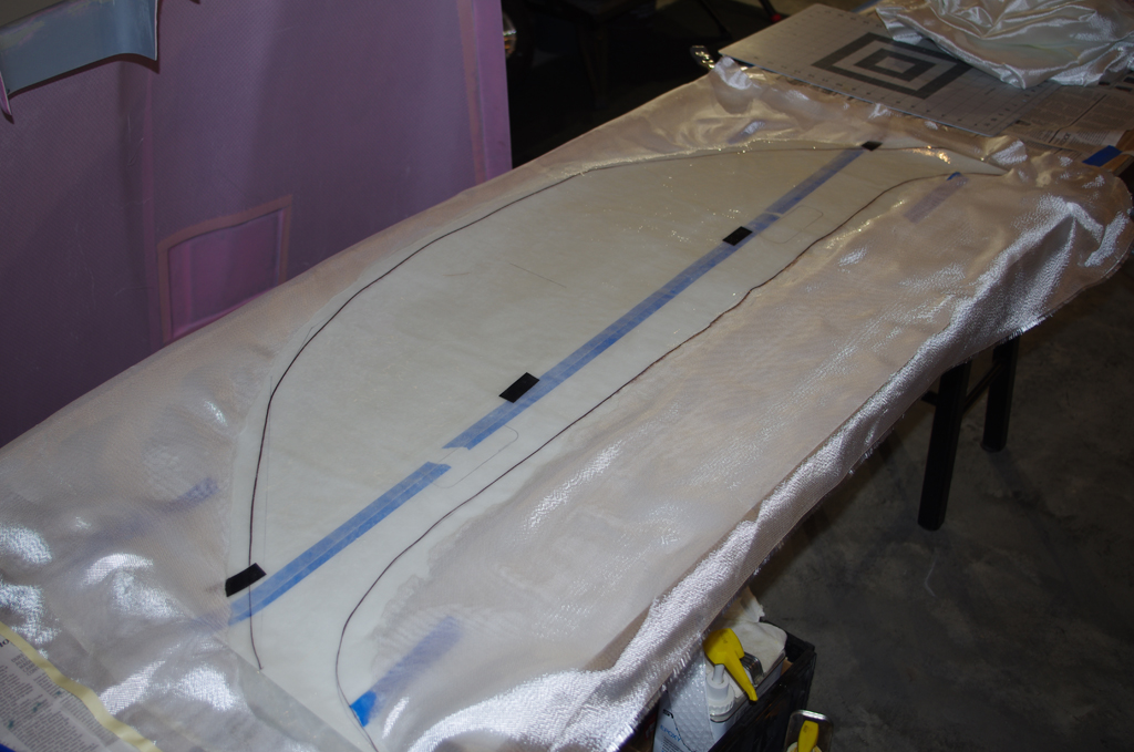
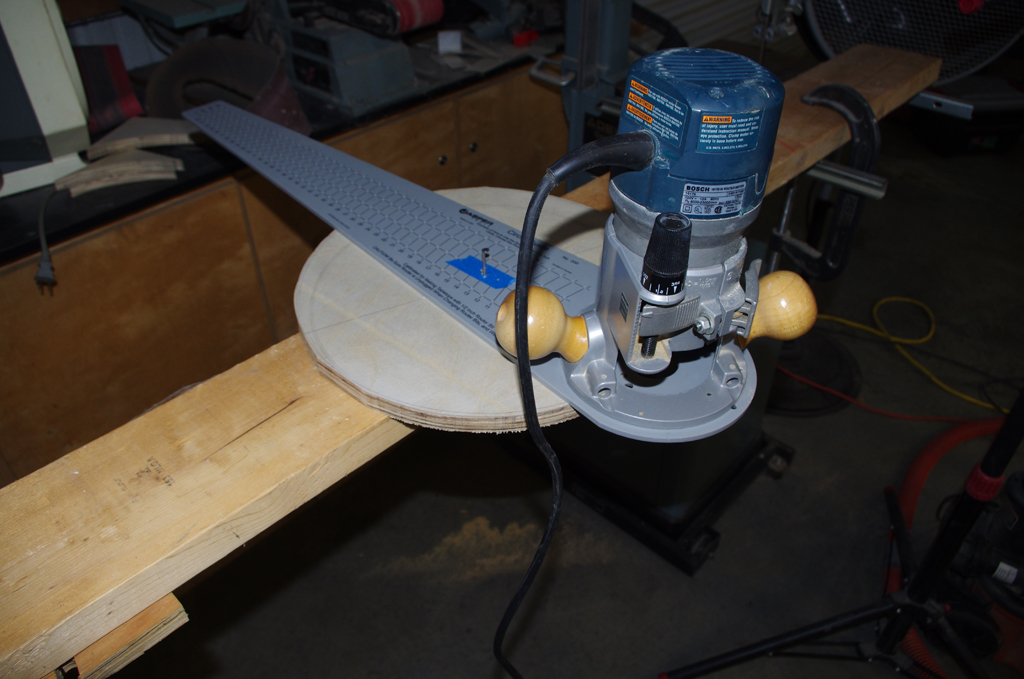
 The rough-cut spinner disc was rounded smooth using a router. The 1″ cowl gap was simulated with smaller discs made of plywood and plastic sheets.
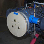
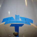
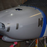
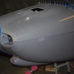
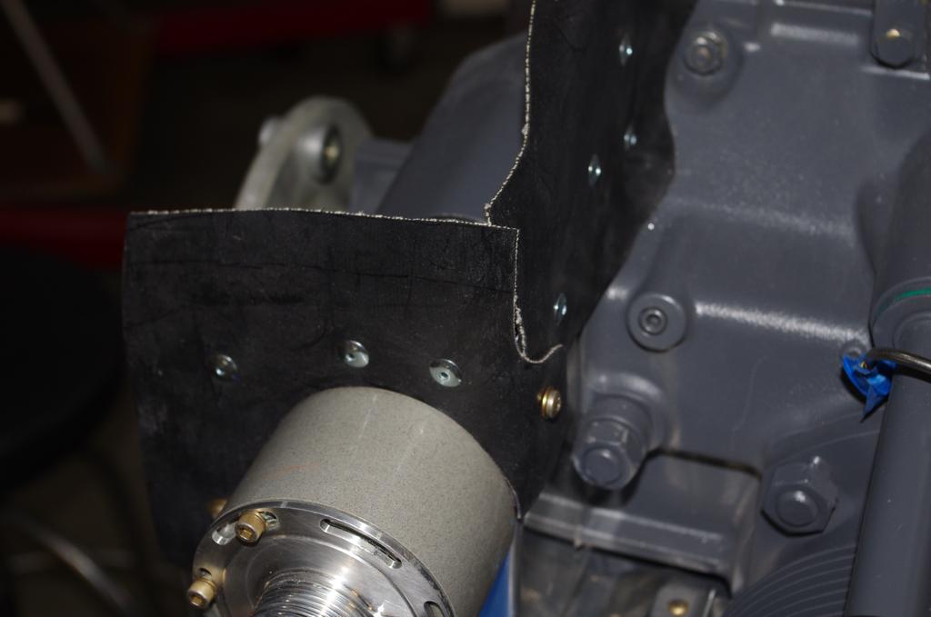
 The mounted reference disc shows where the forward face of the cowl should be. All cowl alignment measures were taken from here.
 This photo shows aligning the center of the spinner disc with the crankcase split.
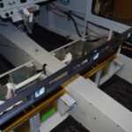
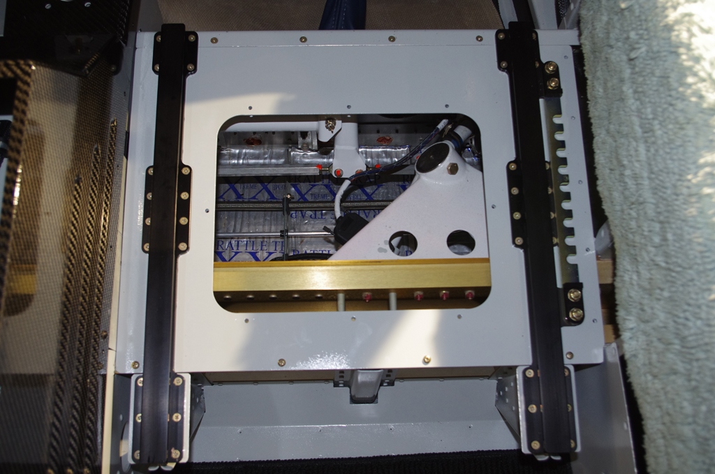
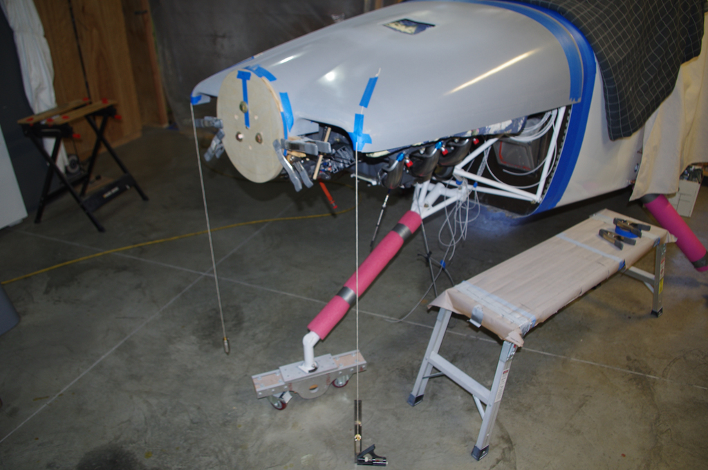
 To properly align the cowling, the fuselage must be leveled laterally. The leveling points are between the door bulkheads in the center of the cabin.
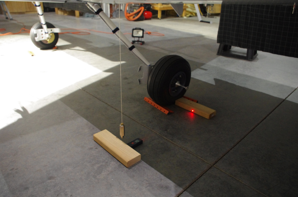
 Next the forward face of the upper cowl is positioned behind the spinner disc, then leveled left-right with the floor using plumb bobs.
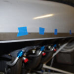
 Level references are marked at the front and rear of the upper cowl. These are used during the trimming process.
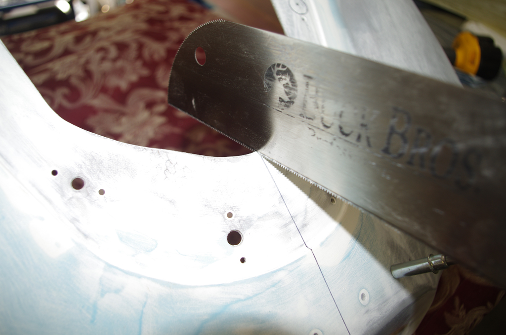
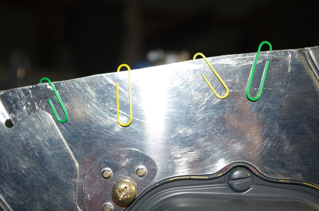
 The first trims are for the firewall gaps on the upper cowling. Anything between 1/16″ to 1/8″ is considered acceptable. Too tight is not good due to paint chipping and difficult fit, while too wide impacts airflow and does not look good. The key for appearance is uniform width along the length of the gap.
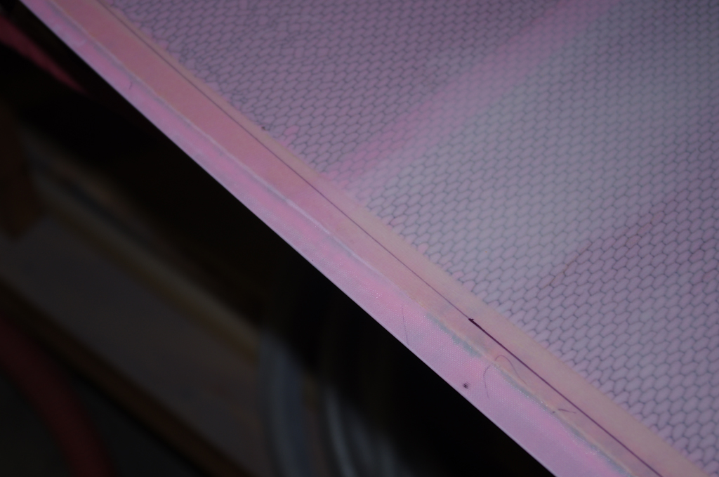
 Next action is position the piano hinges and match drill for fit. Unfortunately, the upper cowl fiberglass had reinforcing honeycomb too close to the edge for the hinge to lay flat. That honeycomb had to be sanded back and layered with fiberglass to provide sufficient edge strength for piano hinge rivets.
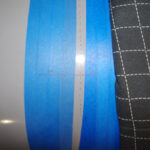
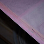
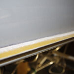
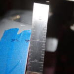
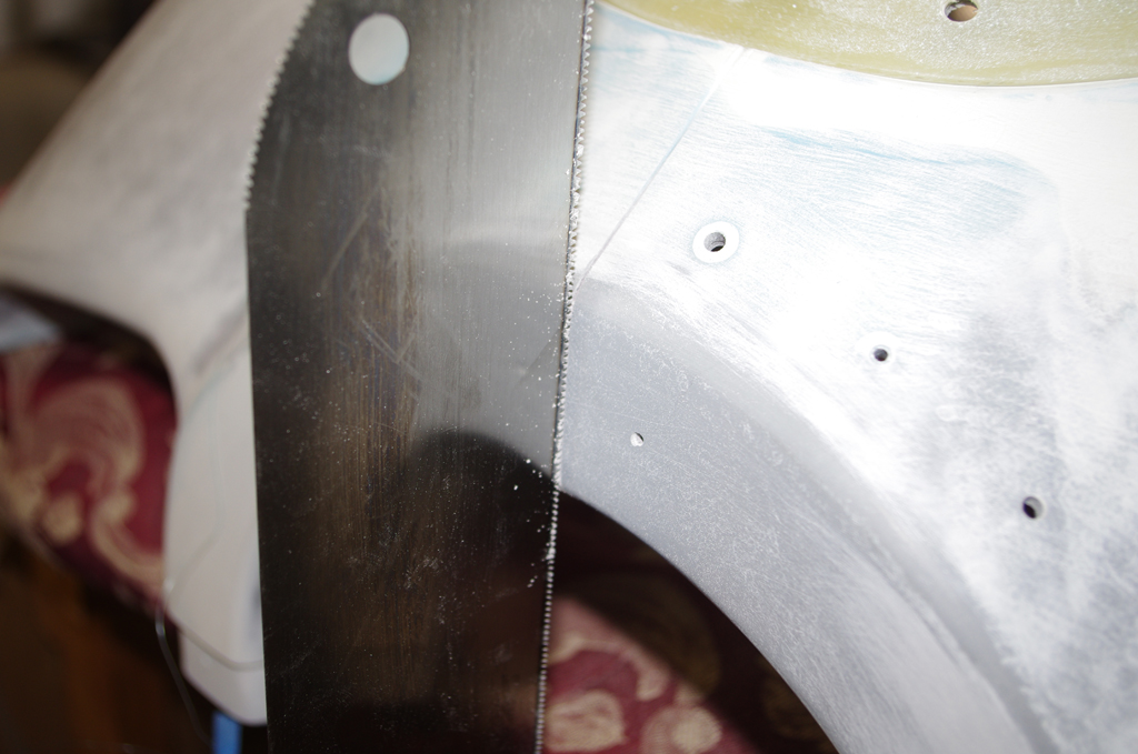
 On the left the final upper gap is shown – a bit less than 1/8″. The right photo shows initial reference line for the cowl side gap.
 Once marked the upper cowl side edge was sanded flat with a 24″ sanding block. This edge became the reference for the lower cowl adjustments. Four inch spacer blocks were attached between the upper and lower cowls, then measurements from the side reference line to the lower cowl.
 The initial cowl side gap is shown here.
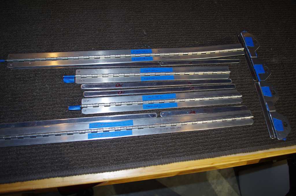
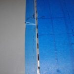
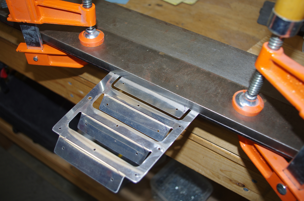
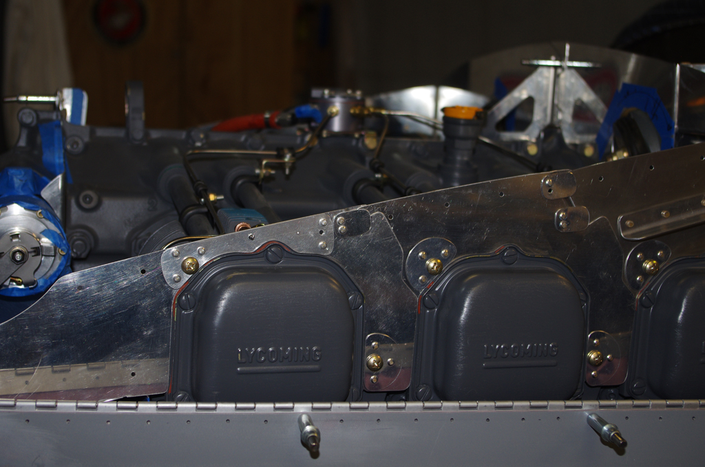
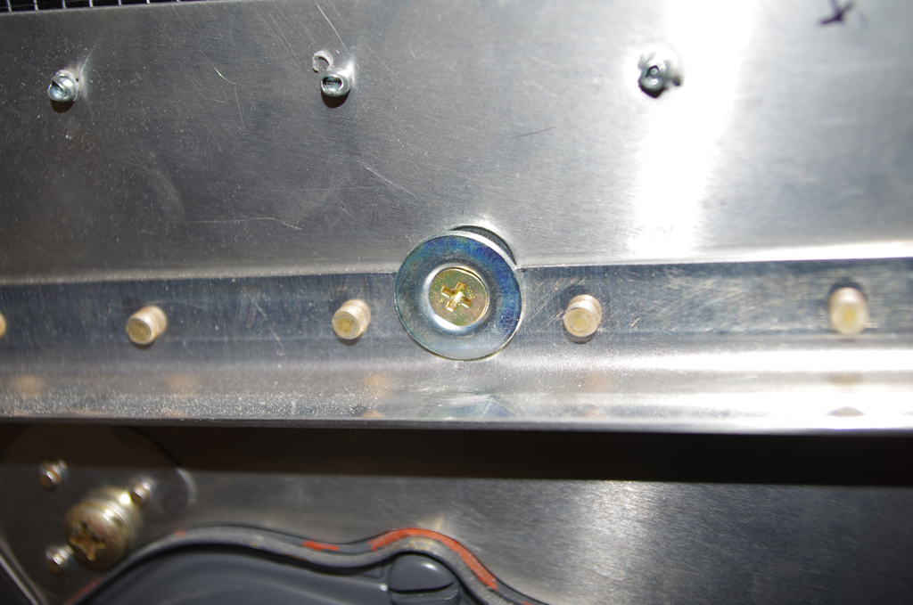
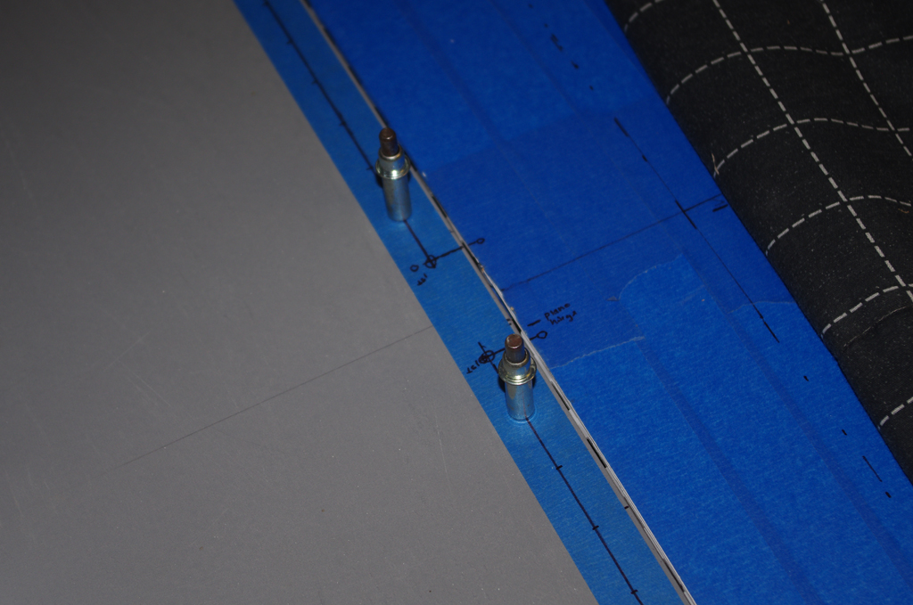
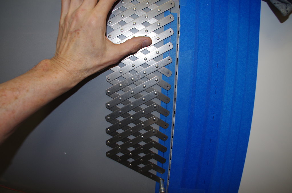
 The hole pattern was used to layout locations 1″ apart for the firewall side piano hinges. The resulting pattern established the permanent gap a bit less than 1/8′.
 The same patterning process was performed on side piano hinges.
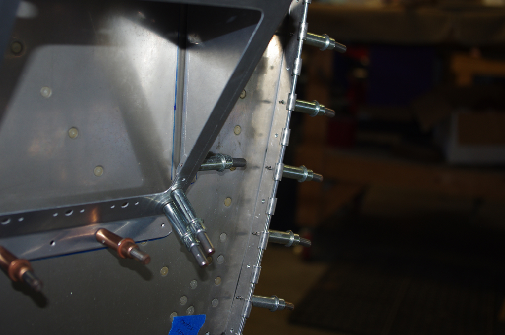
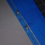
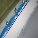
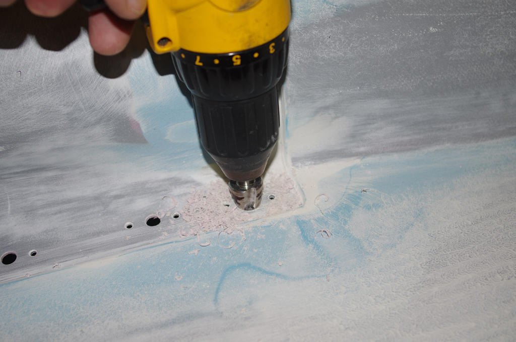
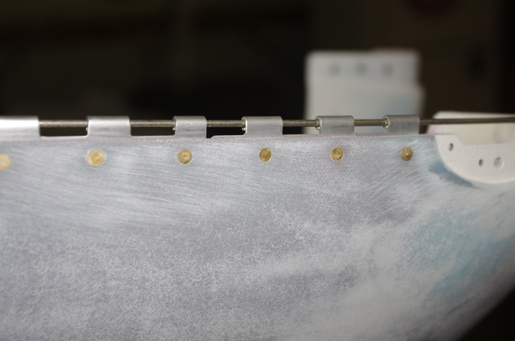
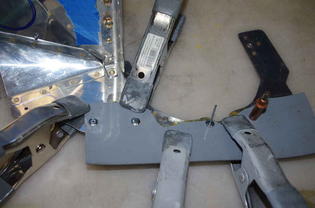
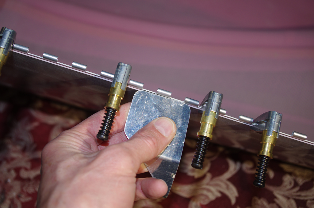
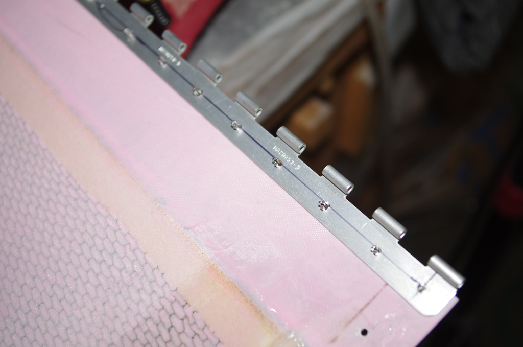
 A spare piece of .030″ aluminum with one side covered with self-adhesive sandpaper was used to create a uniform distance from the hinge web to the fiberglass edge. The lower cowl was drilled from the inside out, then clecoed in place.
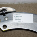
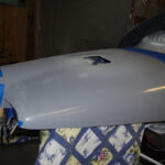
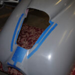
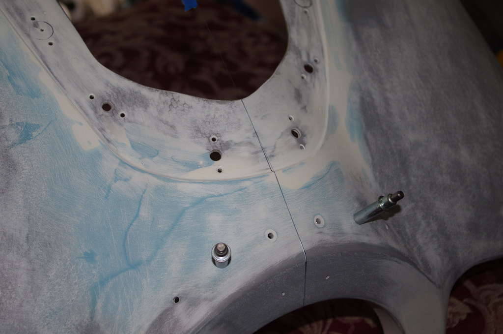
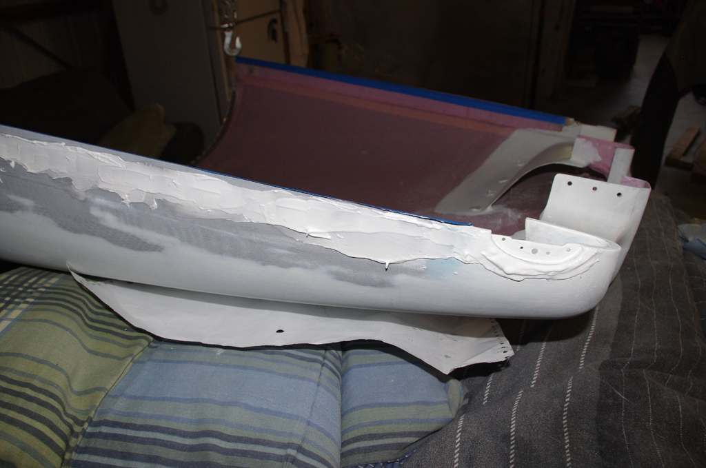
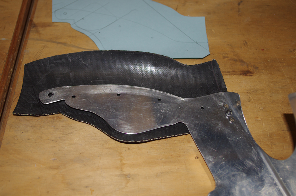
 The forward section cowling was roughly cut for the outline of the Aerosport pin retention plate. The right photo shows the first smoothing steps on upper cowl.
 The forward edges of each cowl did not align properly, so resin/glass bubbles were applied to provide a smooth transition. Next the final fitting of the pin retention template was completed.
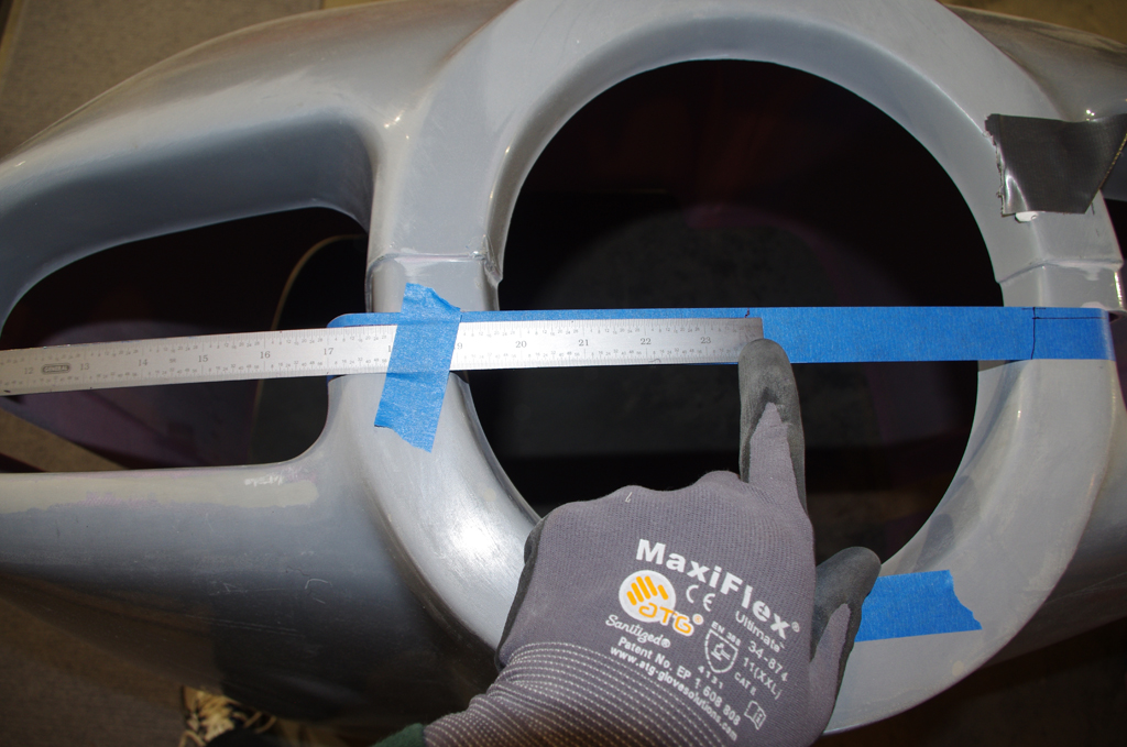
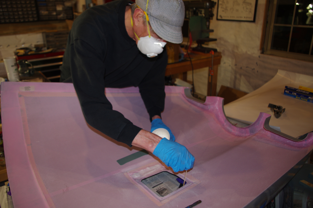
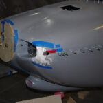
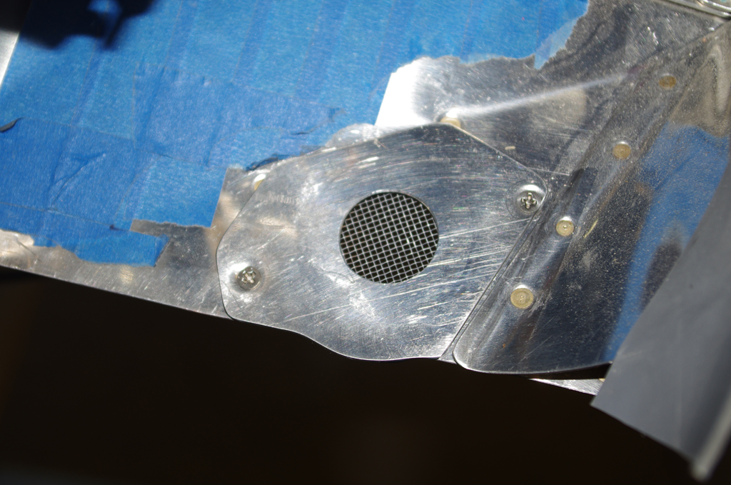
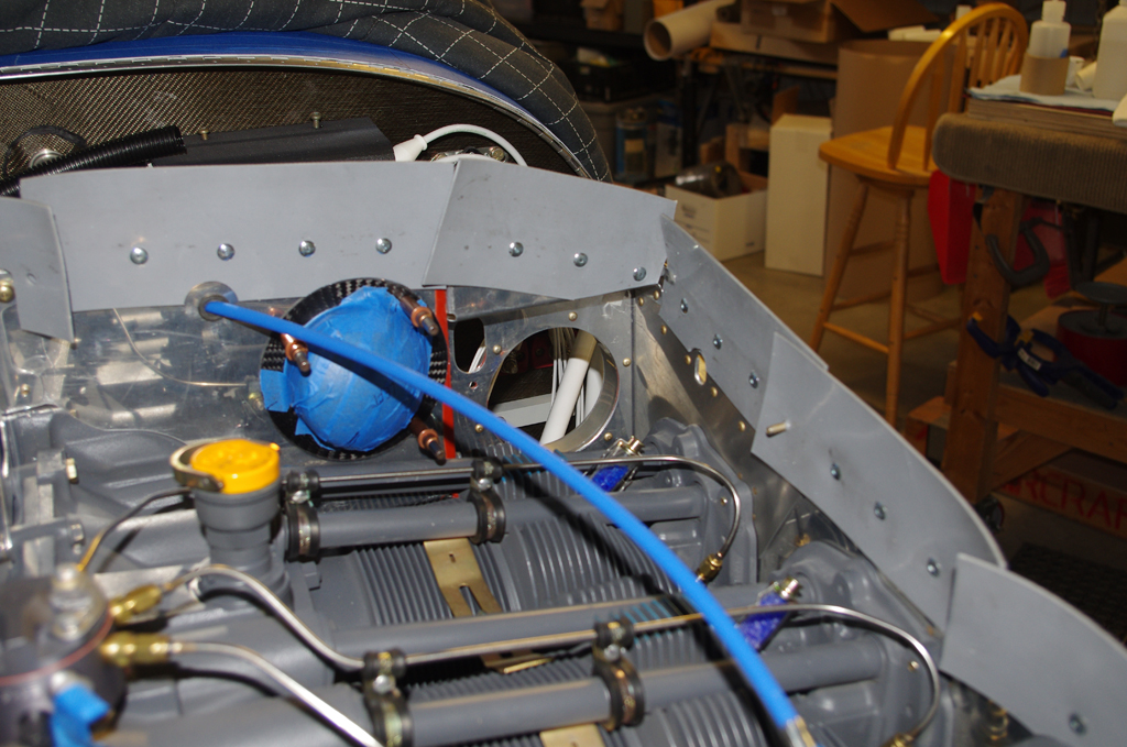
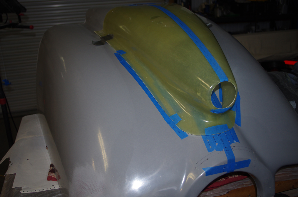
 The Rod Bauer air scoop was positioned above the Van’s default scoop and correct dimensions for the cutout were made. The forward face of the scoop must be about 1″ behind the swinging propeller arc, so very careful measurements were required.
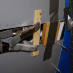
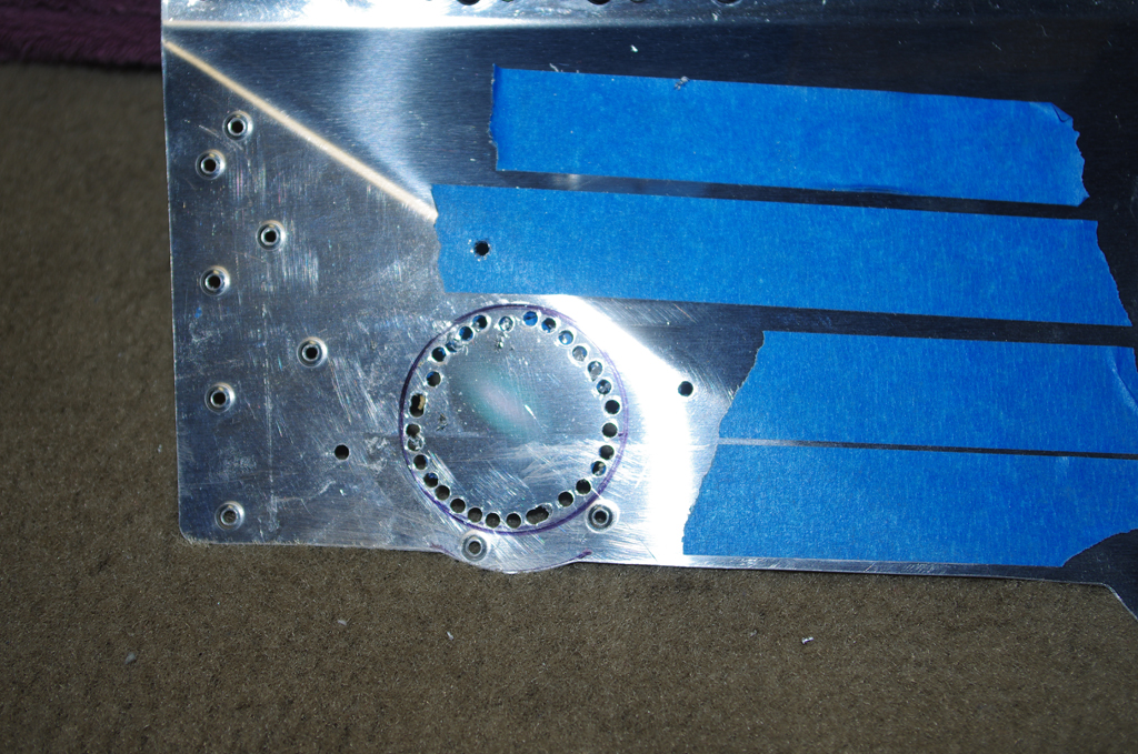
 Puckered and pulled the trigger on the pneumatic cutting wheel to remove the Van’s scoop. This action left a hole just big enough for the K+N air filter housing of the Rod Bower system.
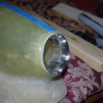
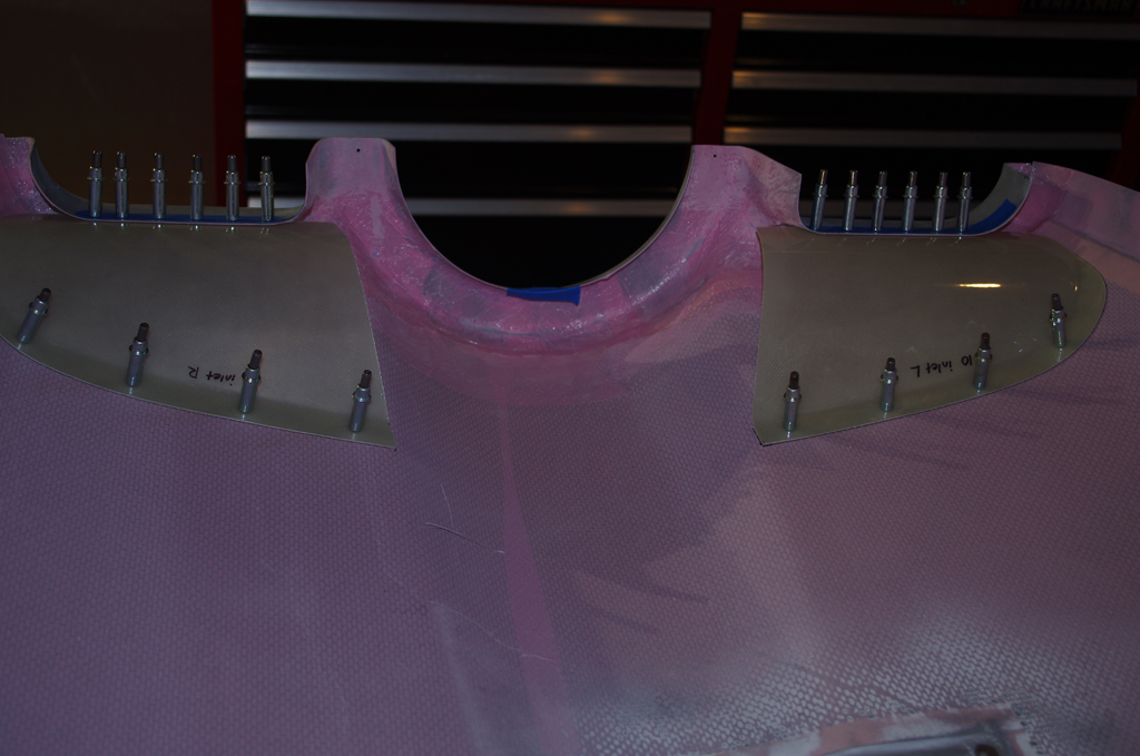
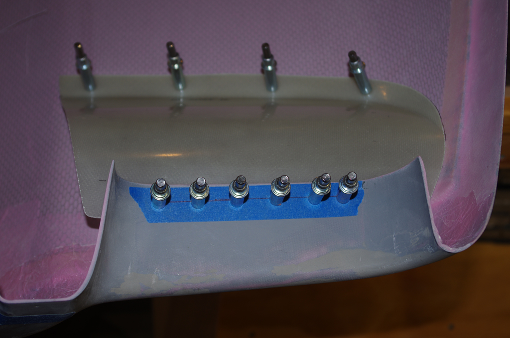
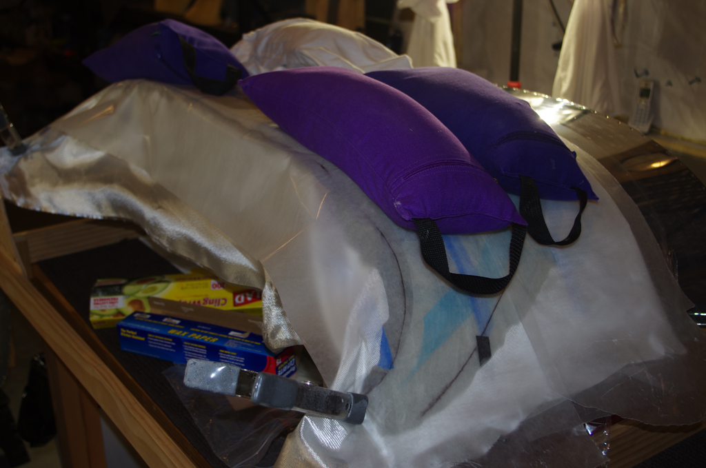
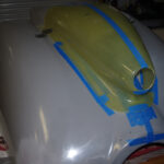
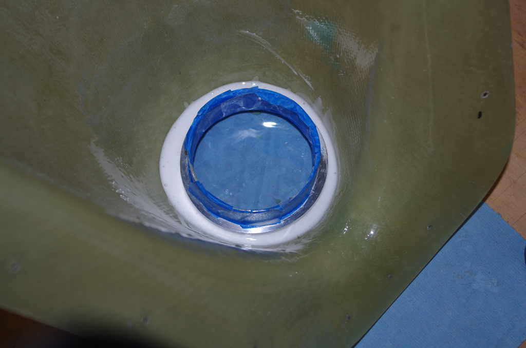
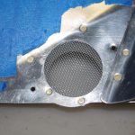
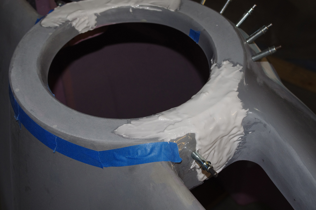
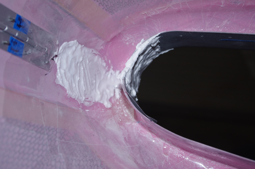
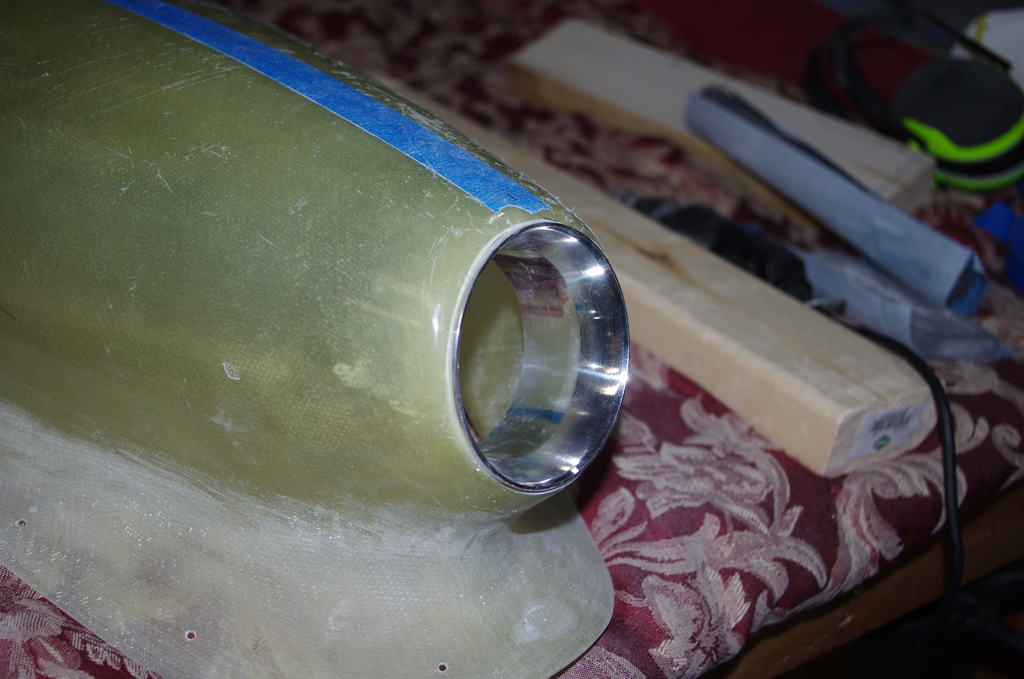
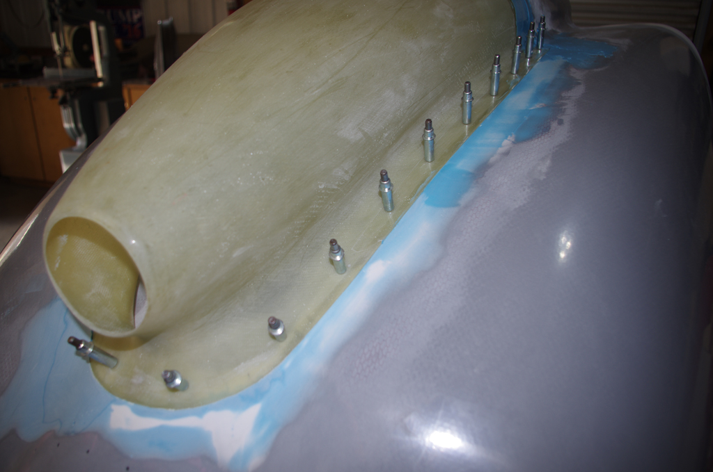
 A test fit of the air inlet ring was made, followed by an initial resin/glass bubble layer around the scoop perimeter.
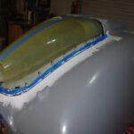
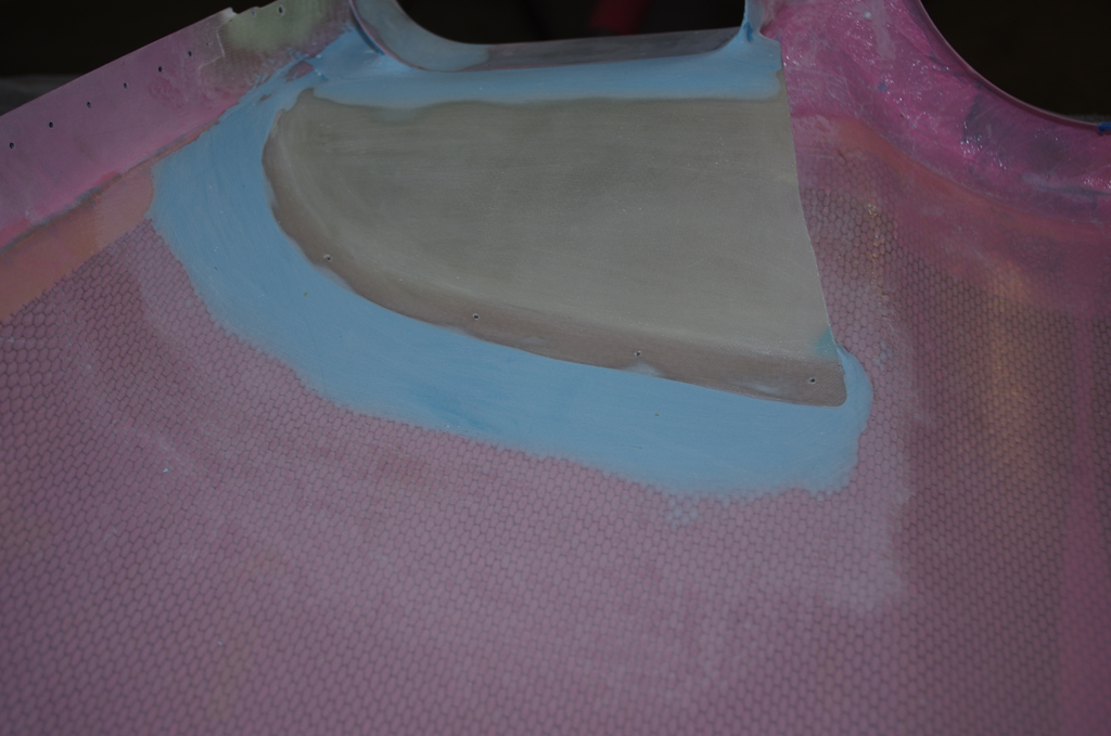
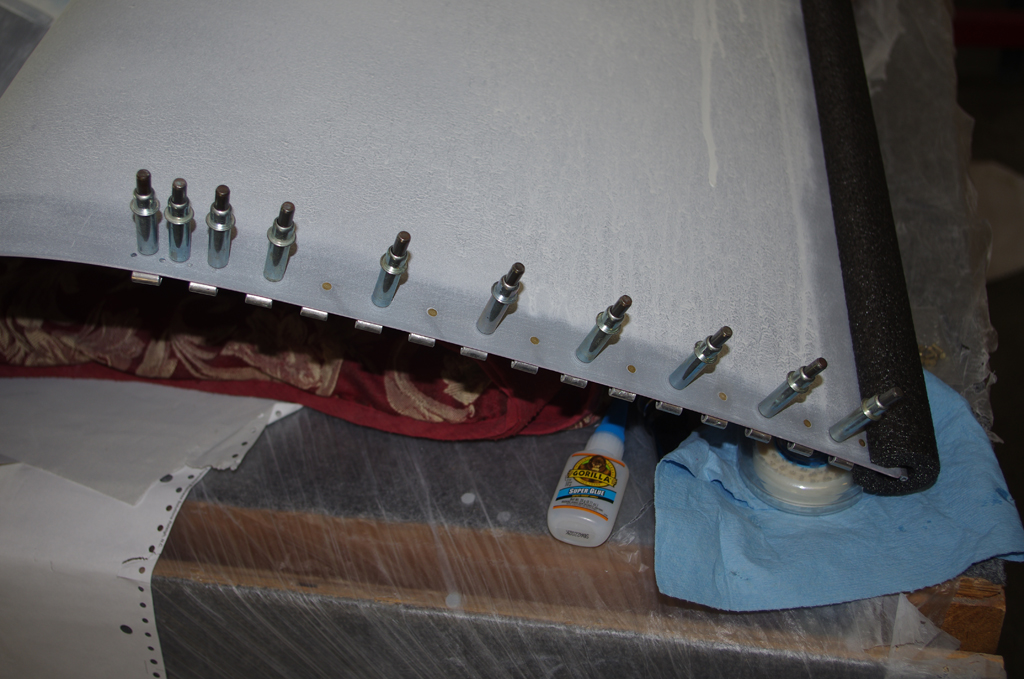
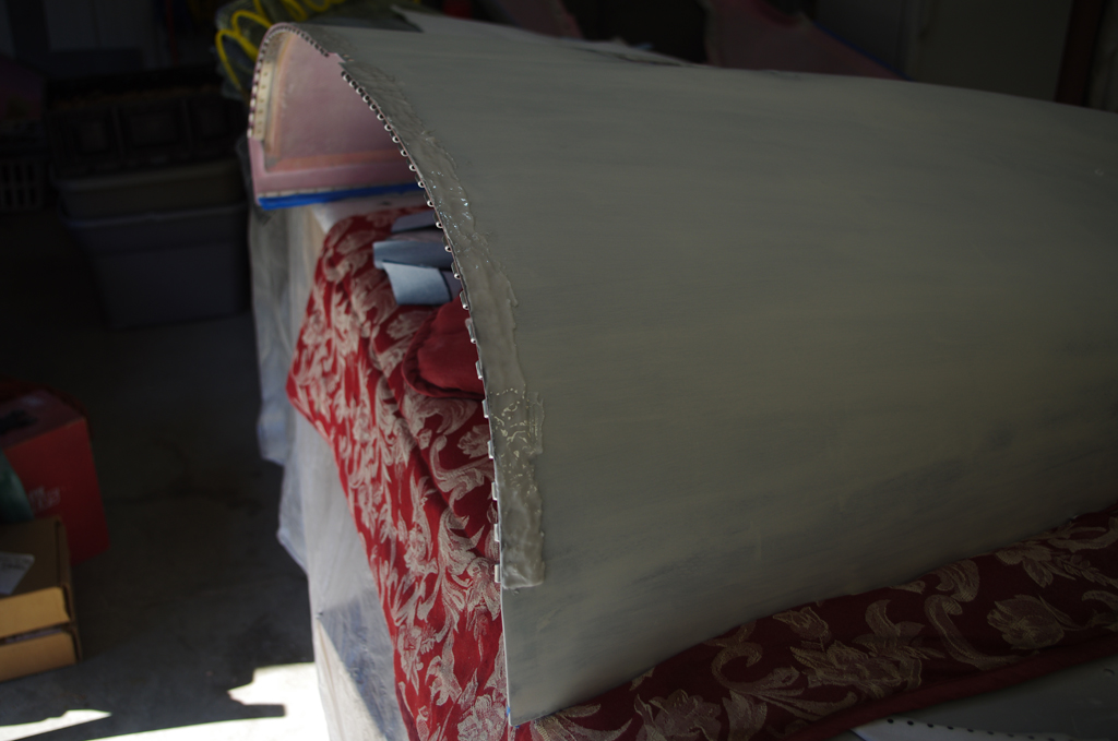
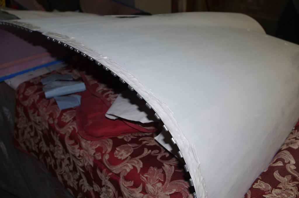
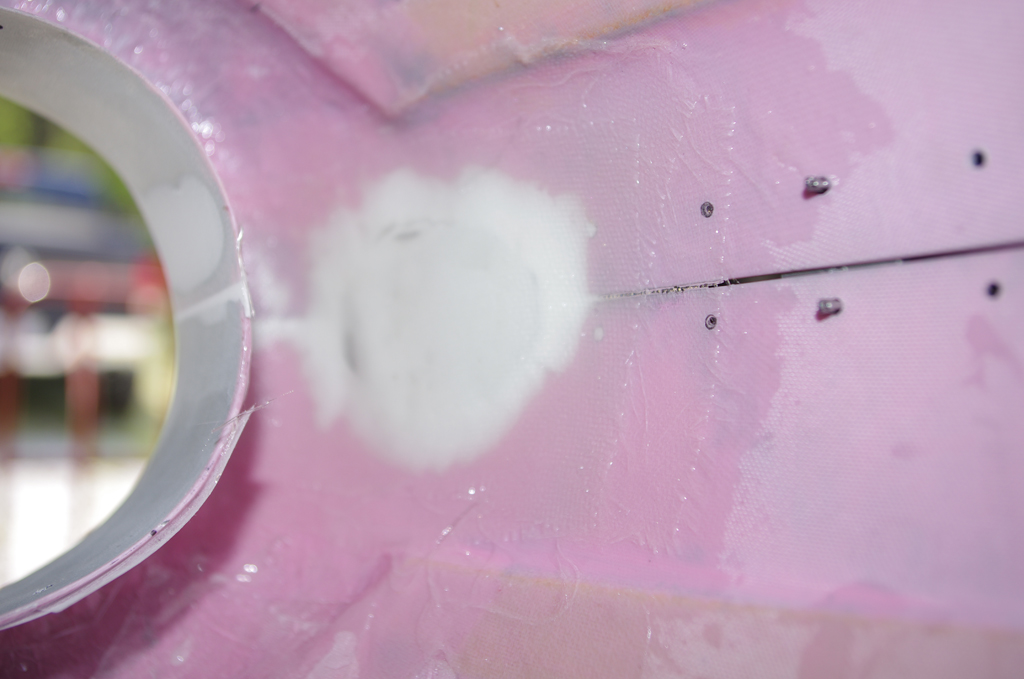
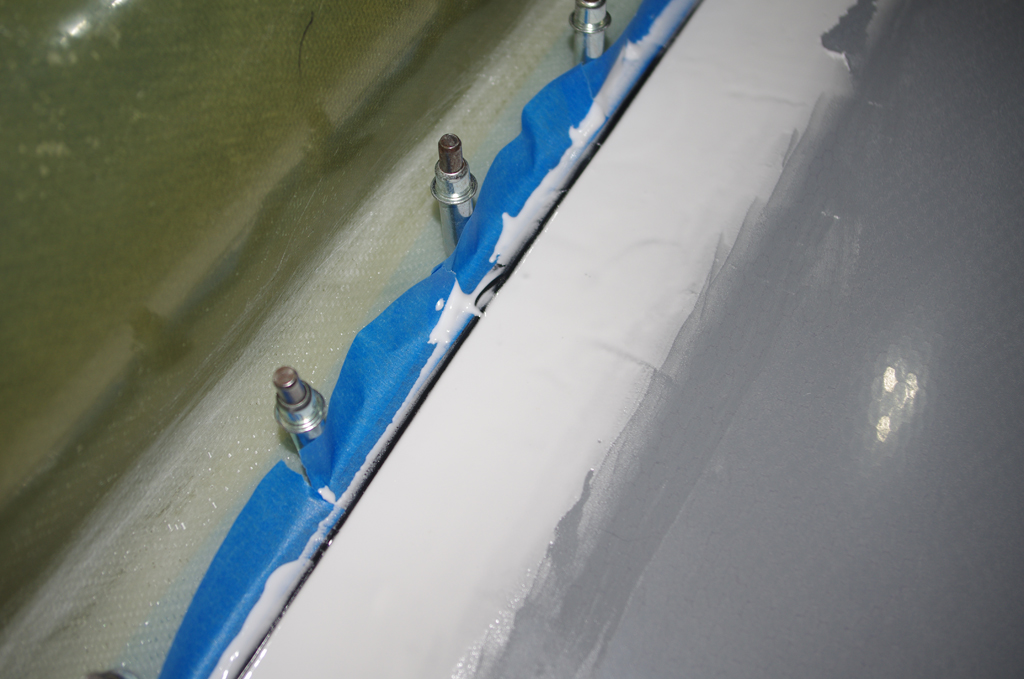
 Multiple sanding and filler applications built up the edges between the original cowl surface and the newly introduced air scoop. Clecoes roughly 2.5″ apart securely held the scoop in position.
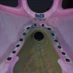
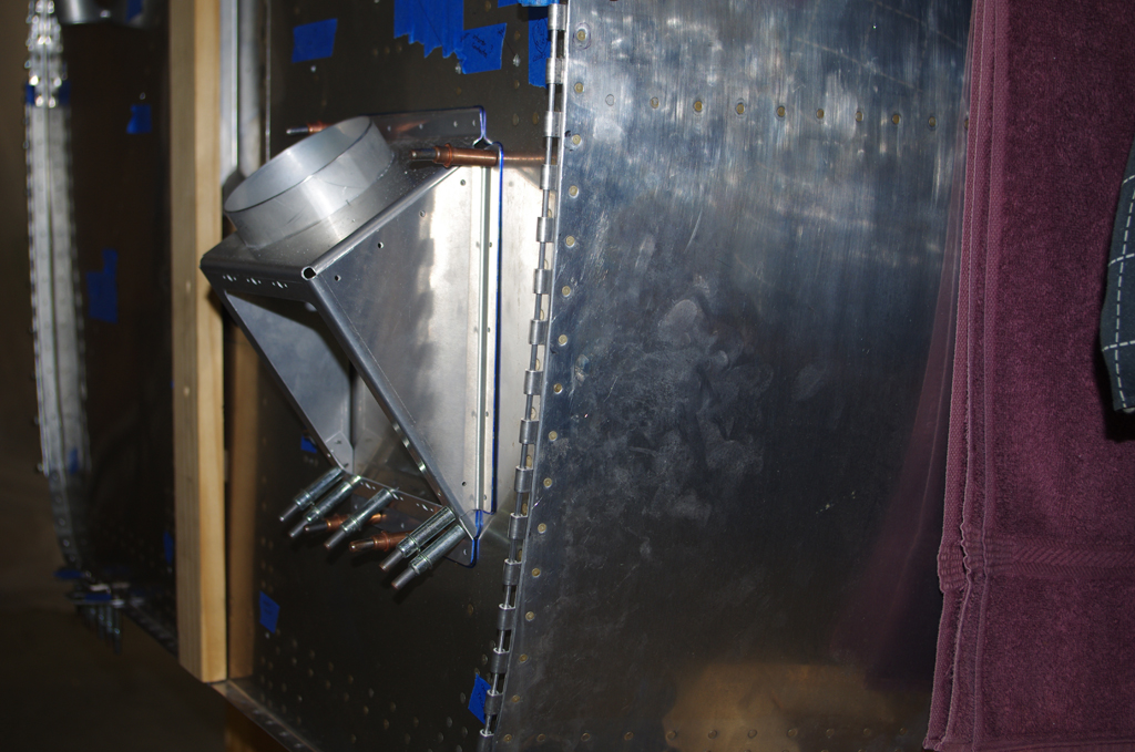
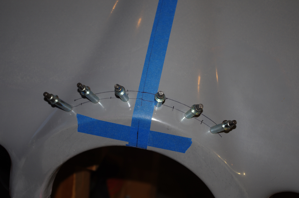
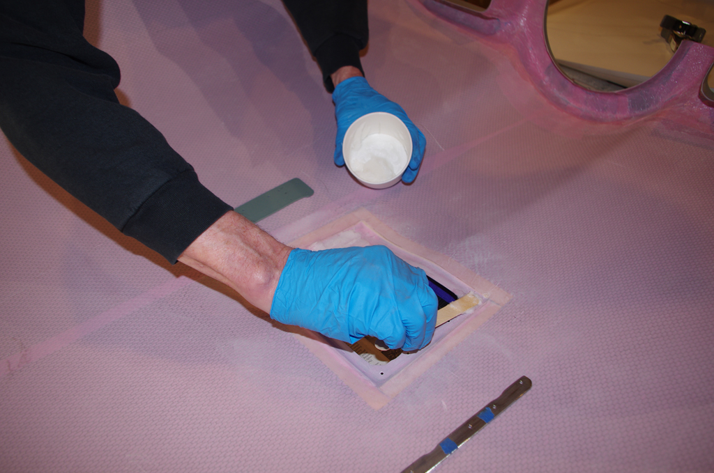
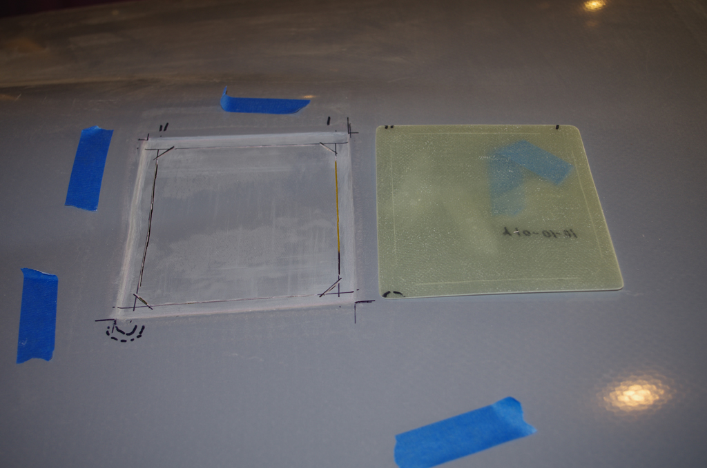
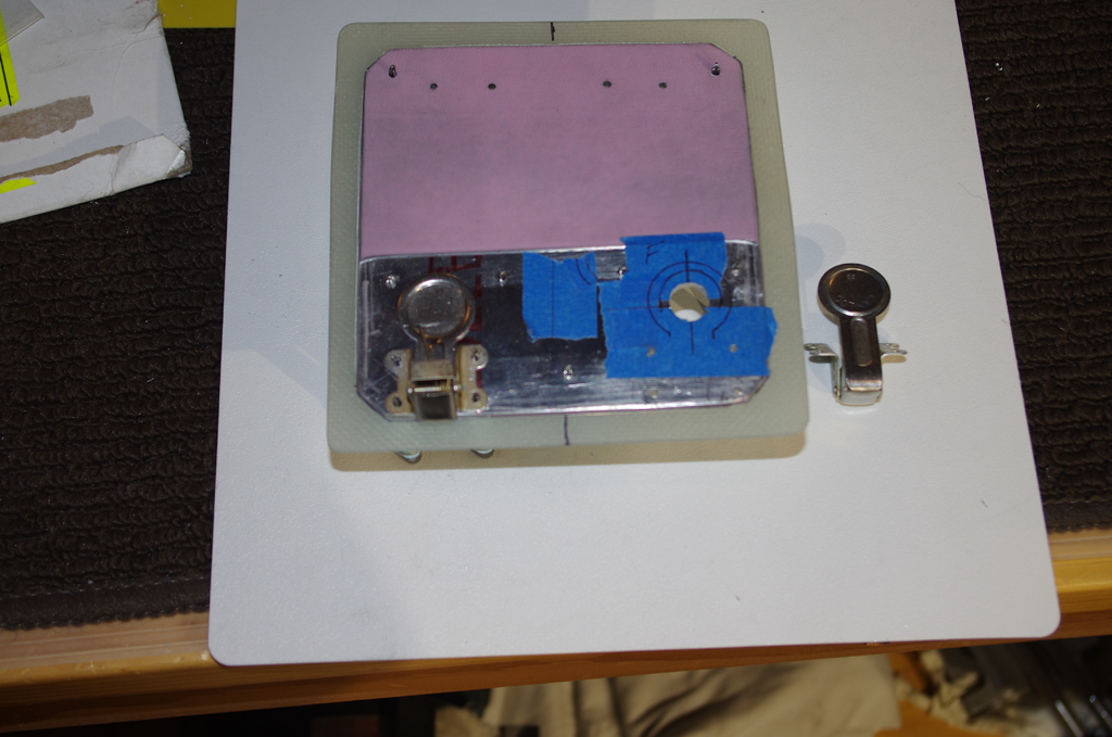
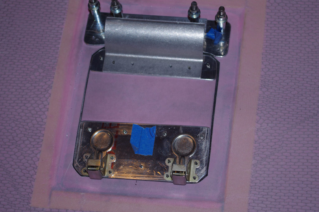
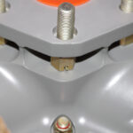
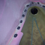
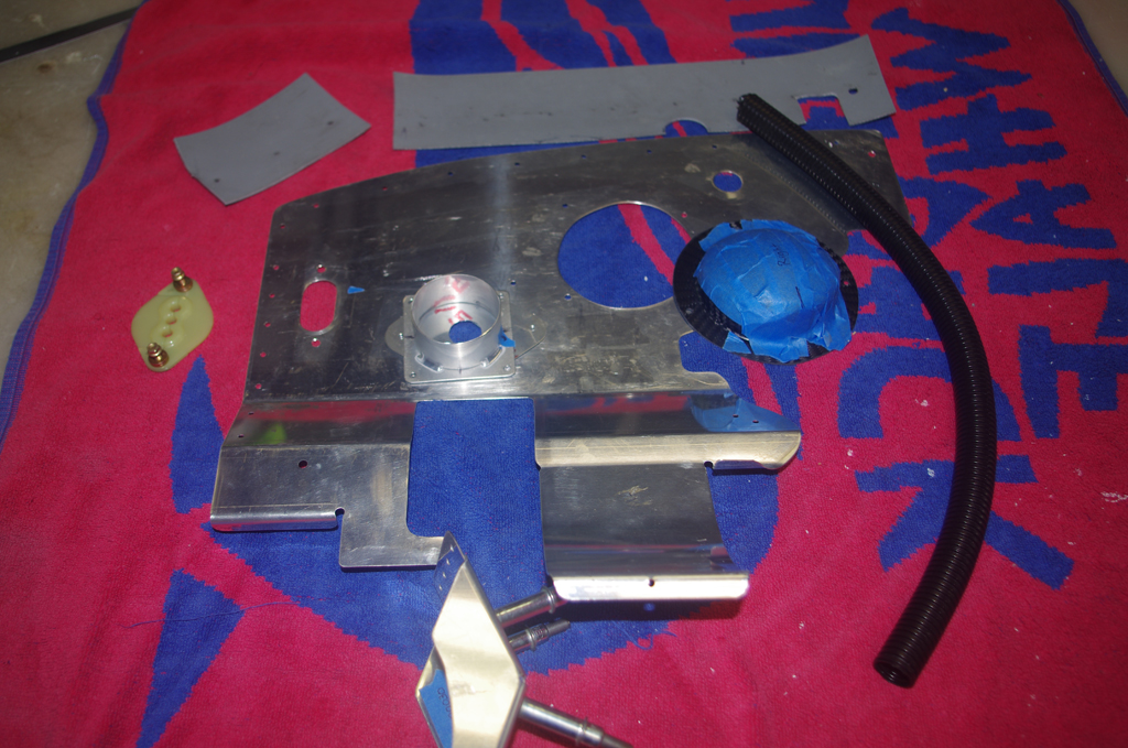
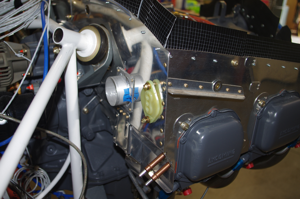
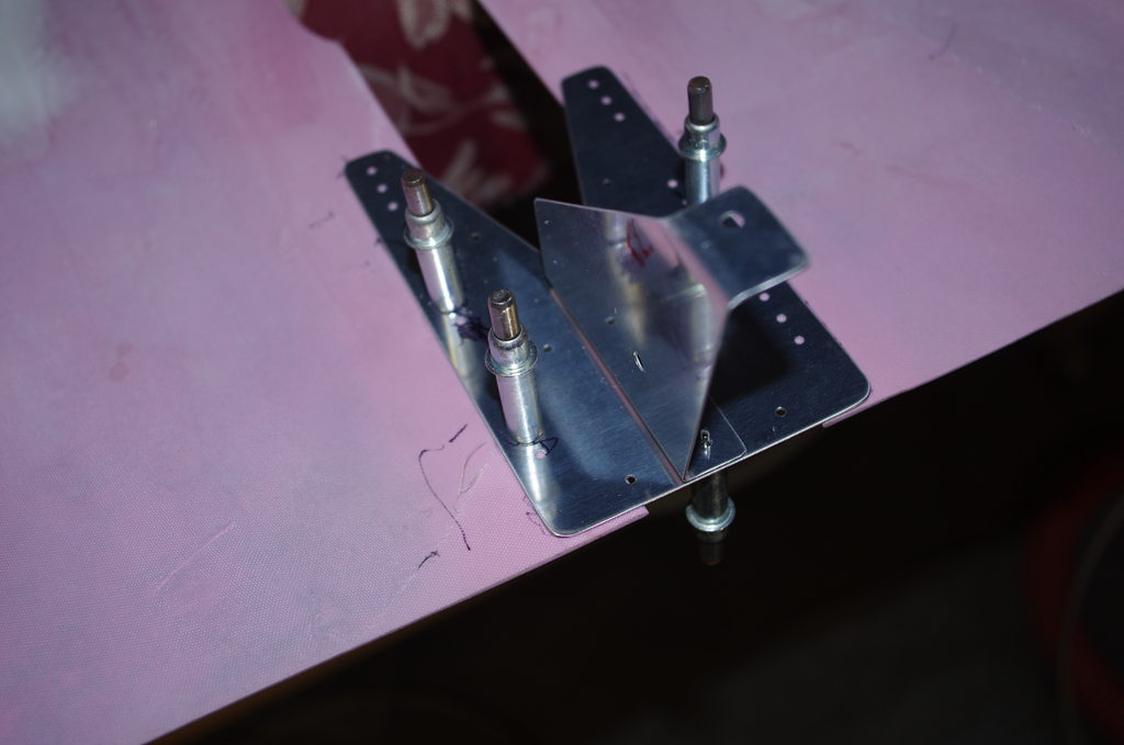
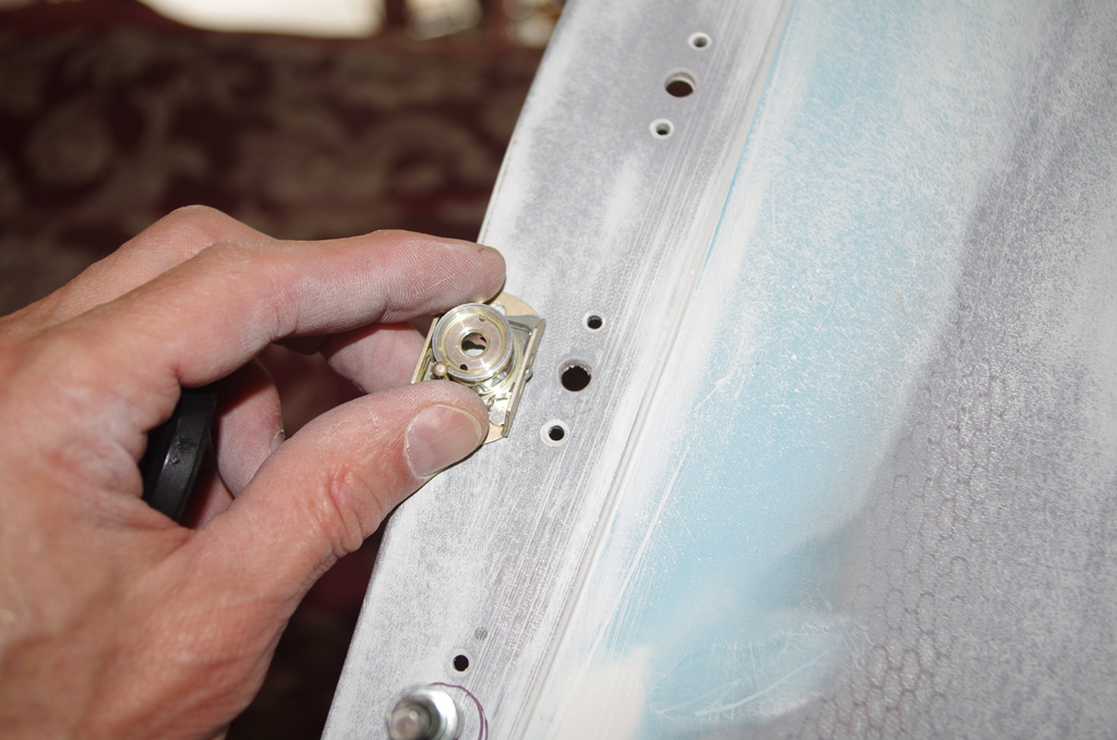
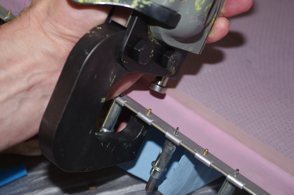
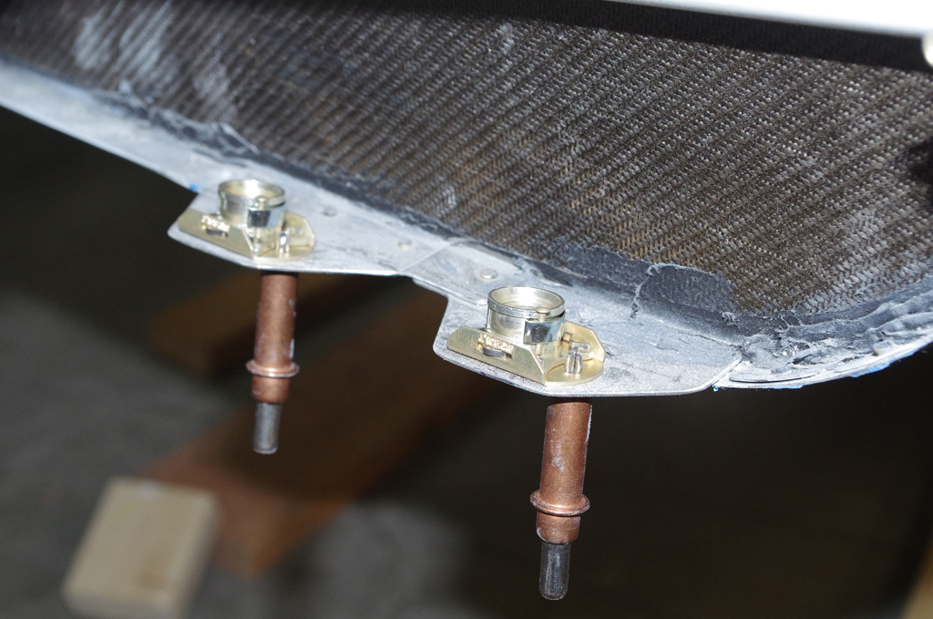
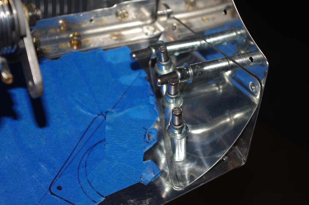
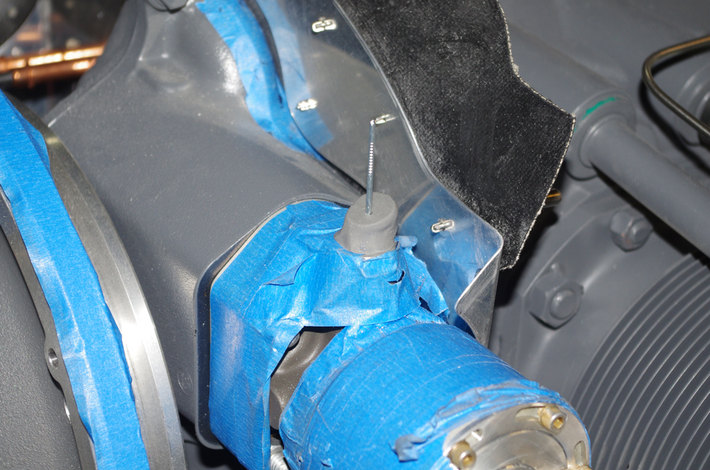
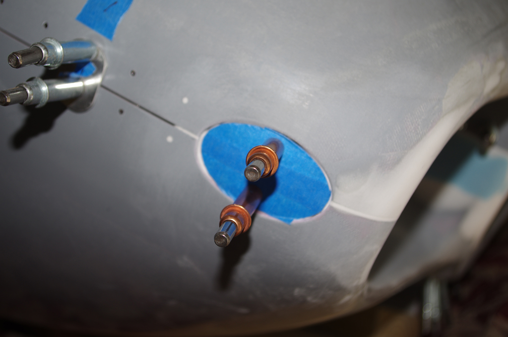
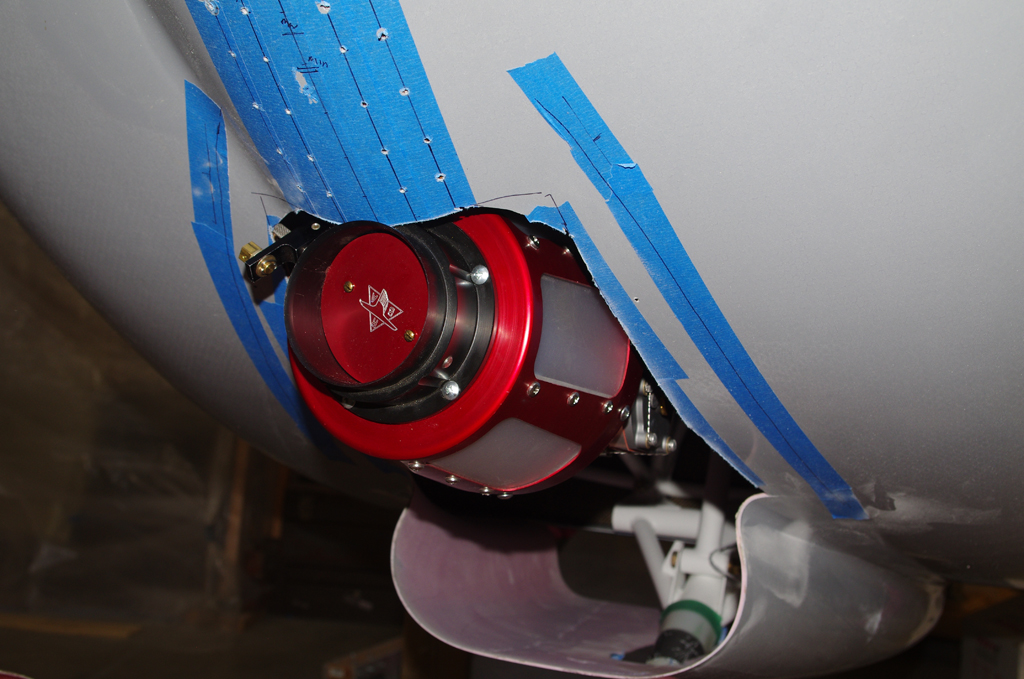
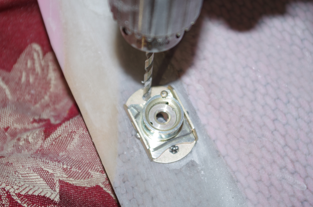
 With the external portions of the scoop under way, the internal locations of Camlok fasteners were determined. As with earlier described issue on the honeycomb webbing, the fastener bases needed relief and then reinforcing for a flat base.
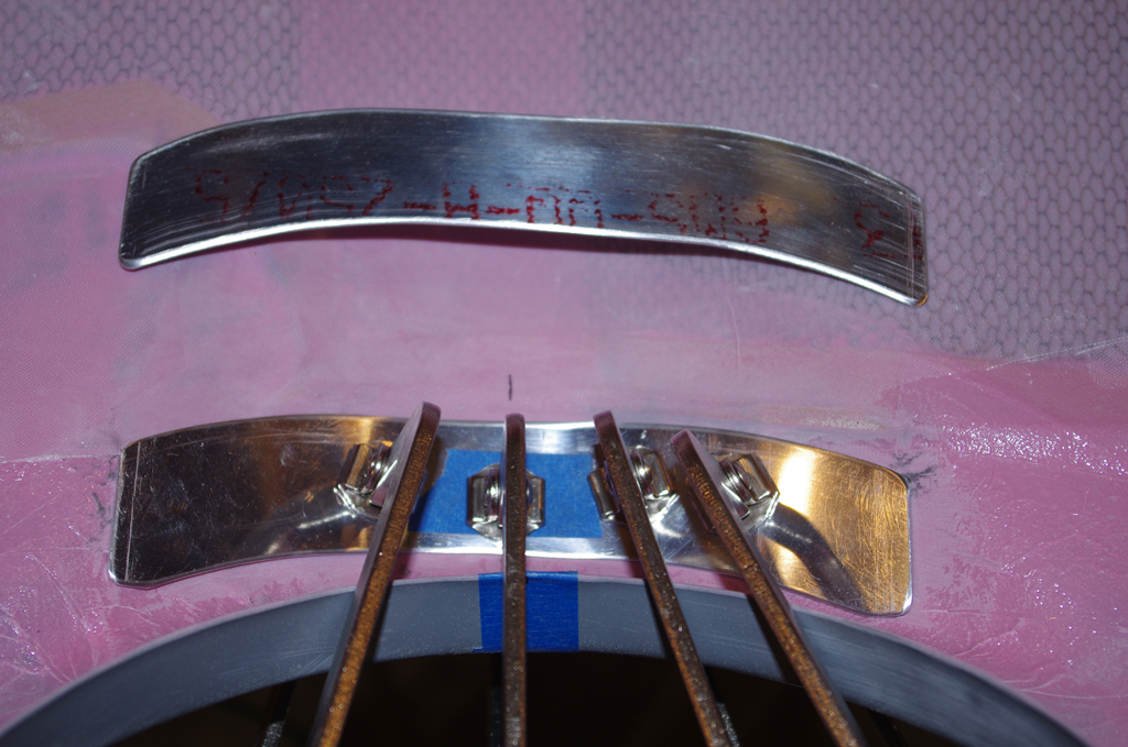
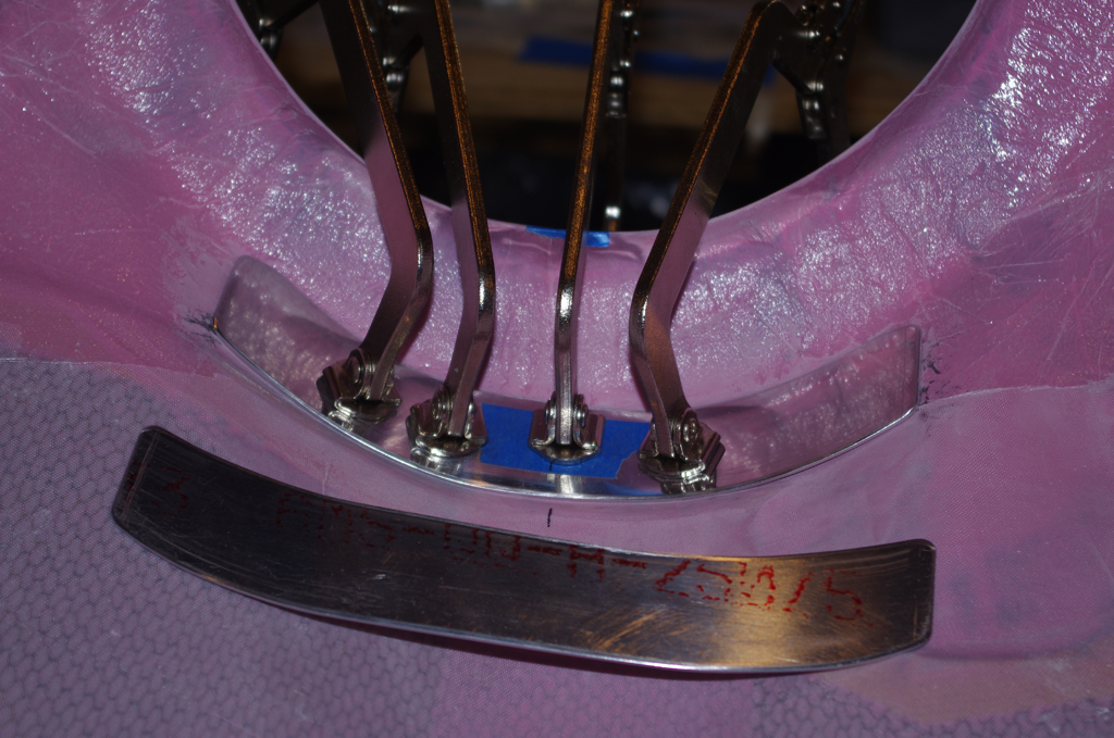
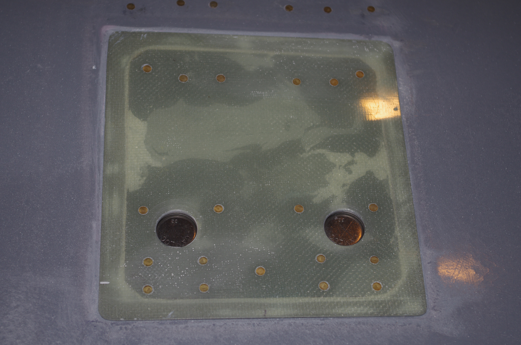
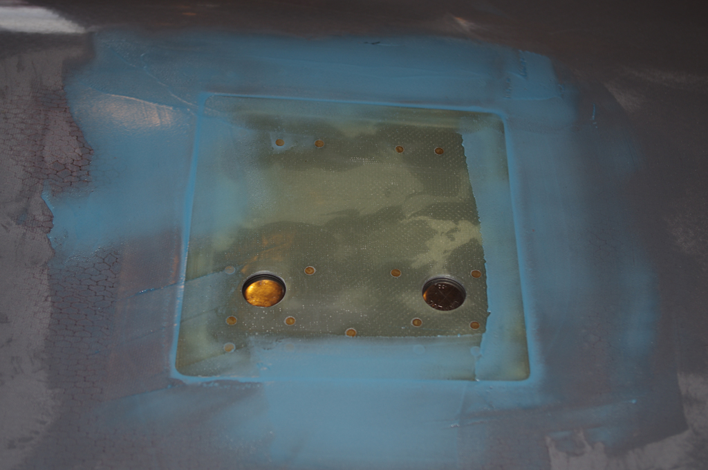
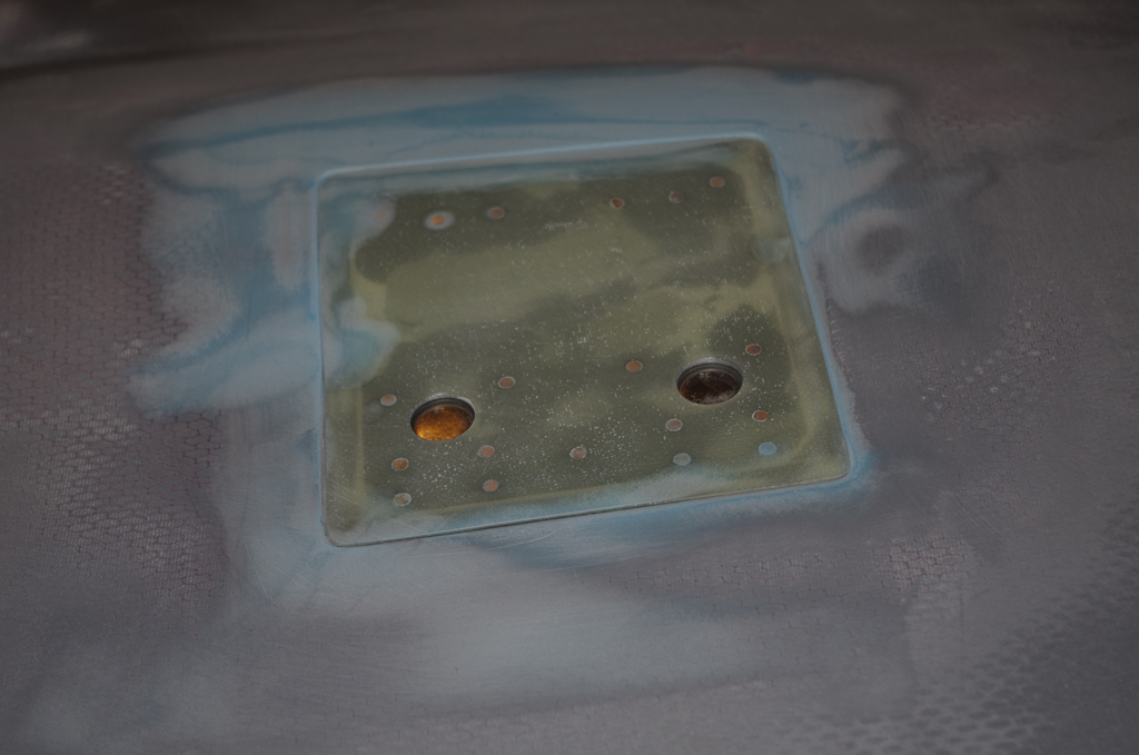
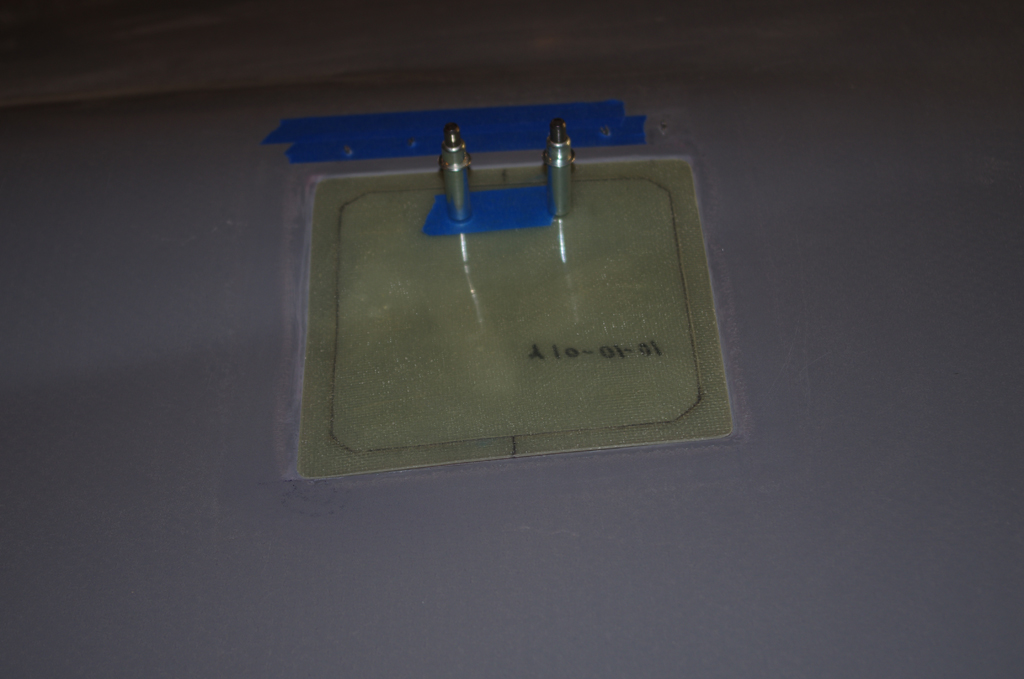
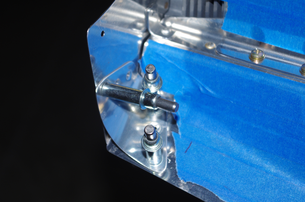
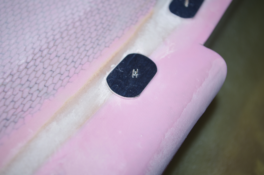
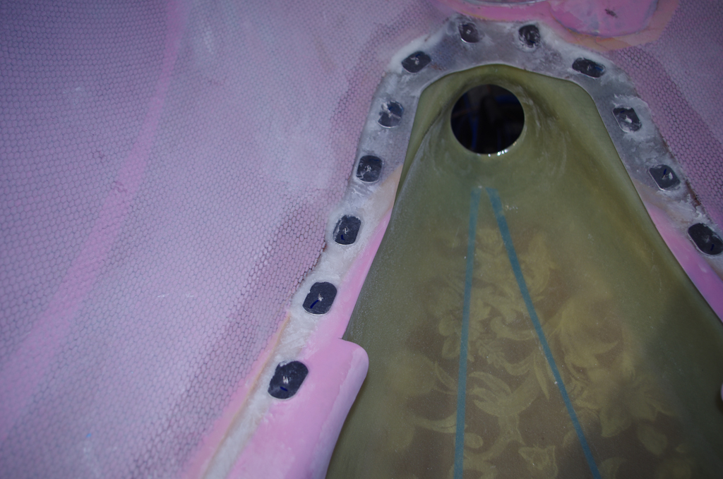
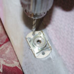 Small base templates were used during the build-up stages, but a real Camlok served as the real template for fastener attach holes.
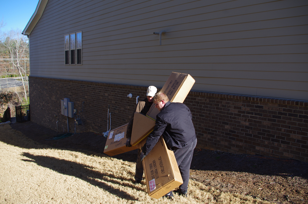
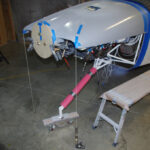
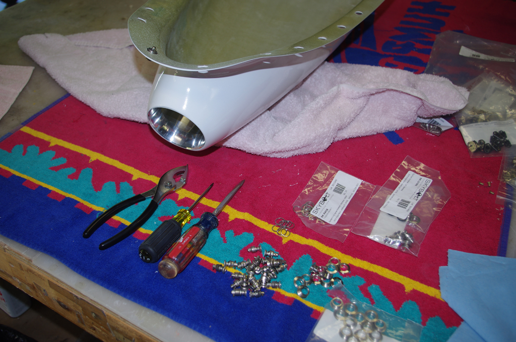
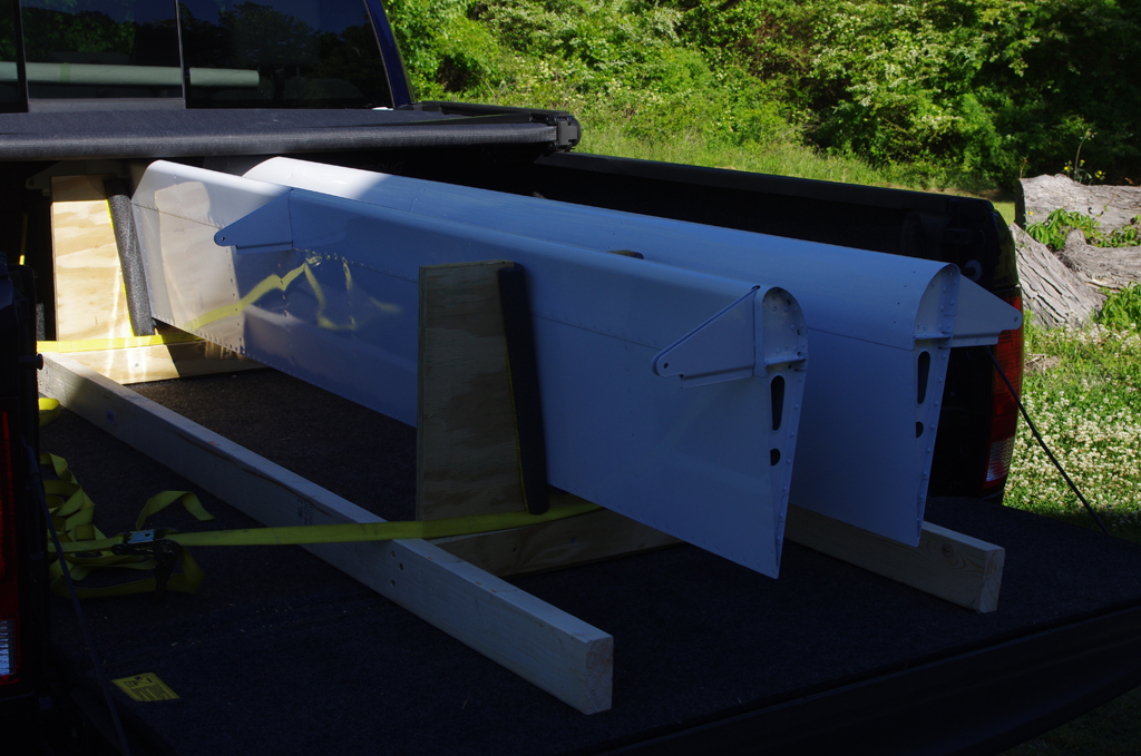
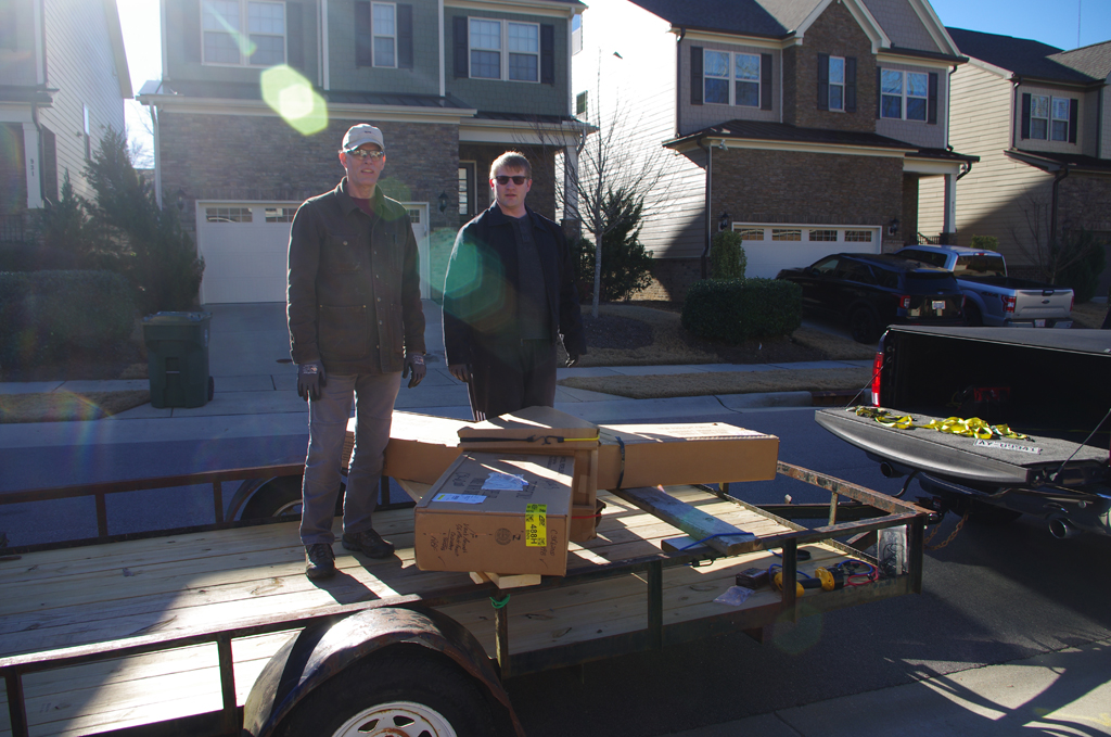 My son and I carried the propeller out of basement storage for transport to the airport.
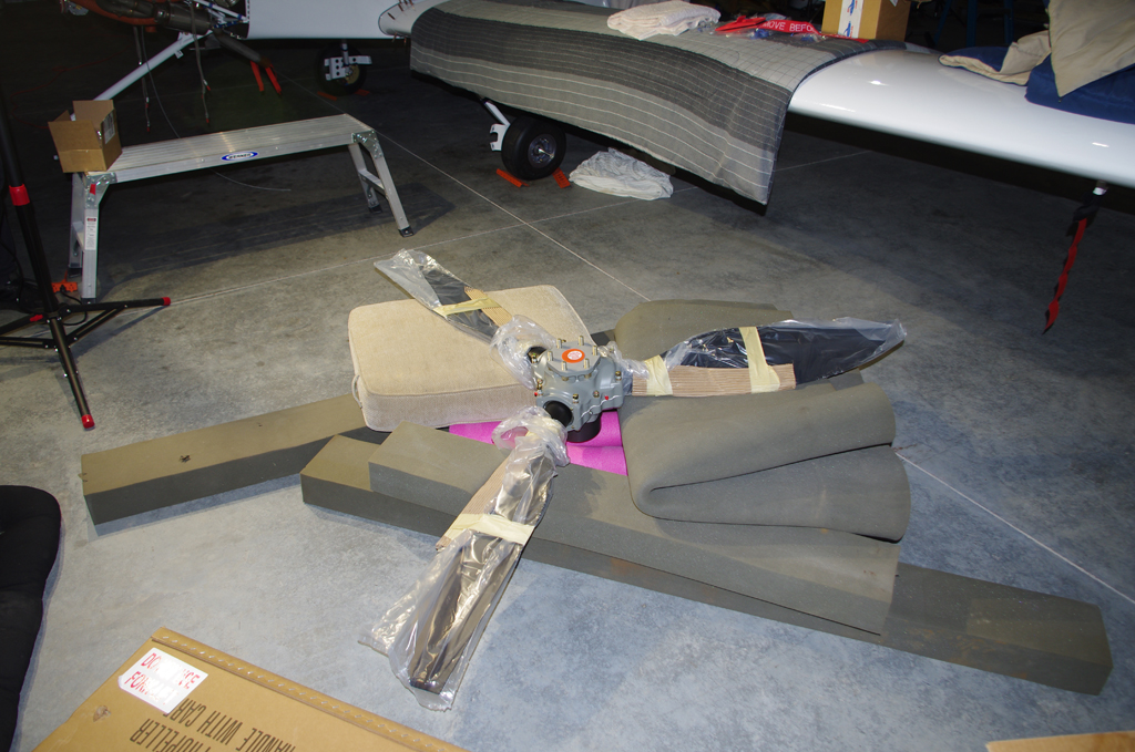
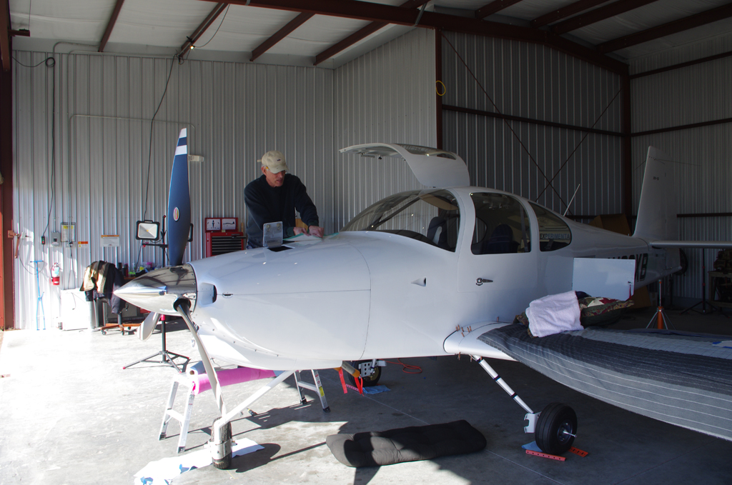
 The unwrapped propeller on the floor was checked, then hung by Terry, Eric and I. Sorry no photos were taken during that process. Needless to say, everything went well and the prop looks great. Easily the best looking thing about the aircraft!
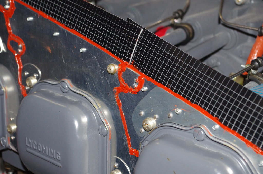
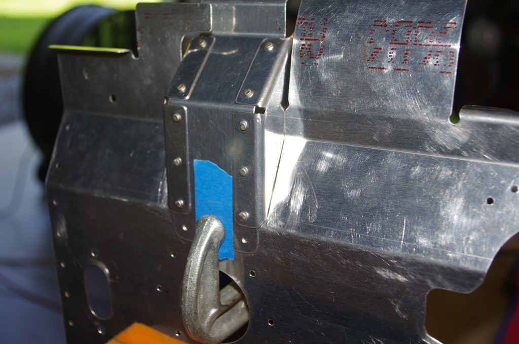
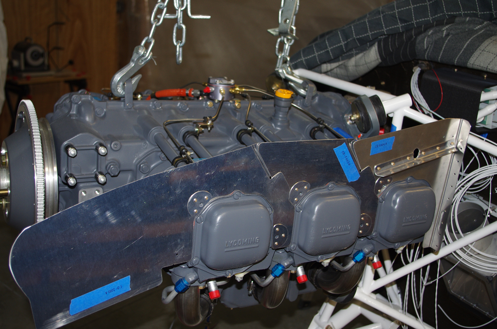
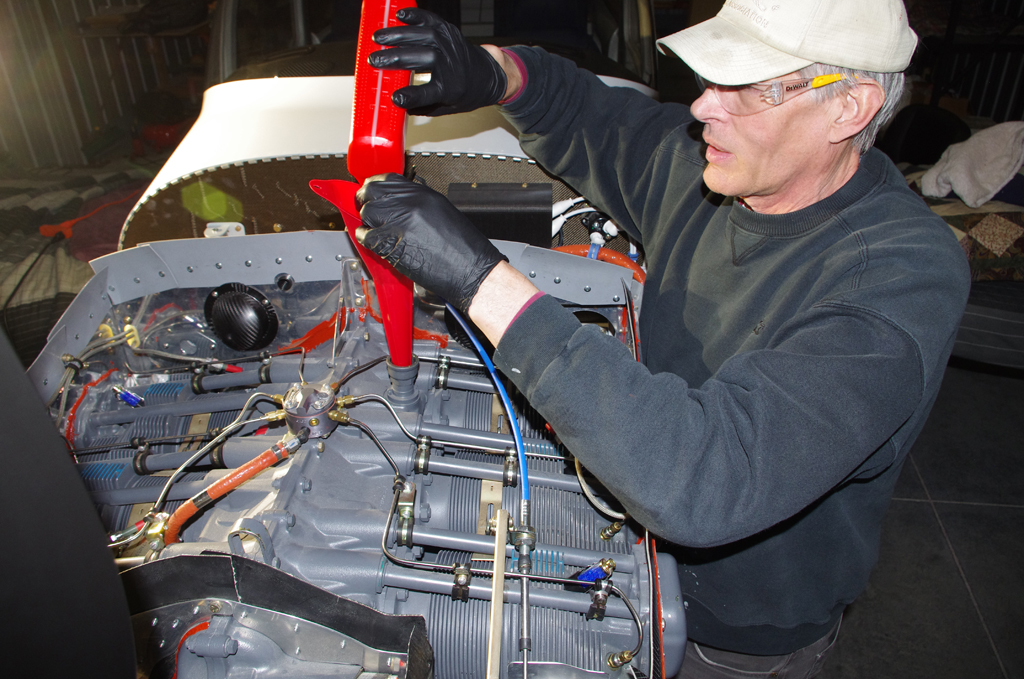 High temperature RTV was applied to gaps in the baffling and between cylinder heads. The engine was then filled with 12qts of Aeroshell 100 mineral oil, which will be used for the 25-30hour engine break-in period.
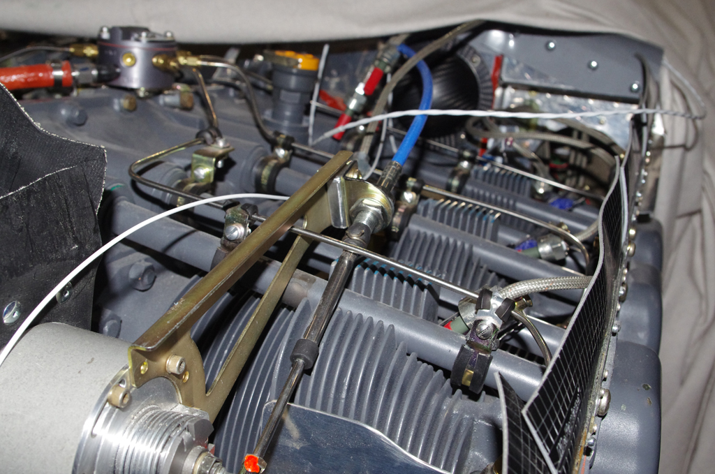
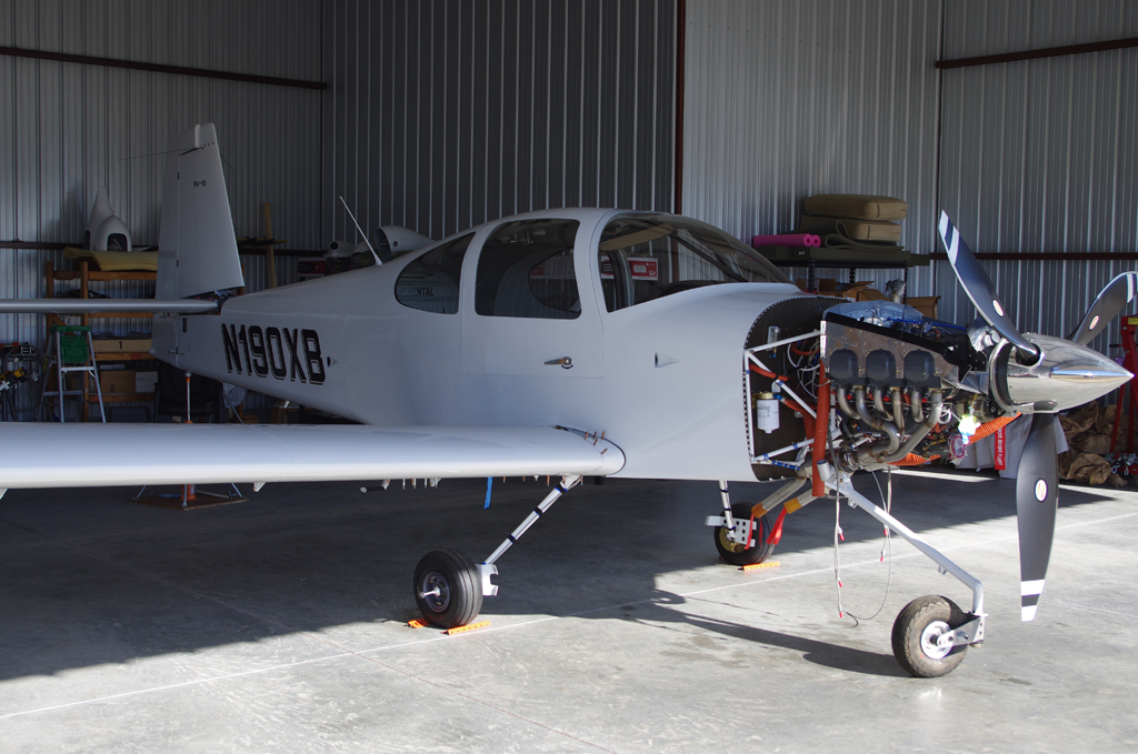
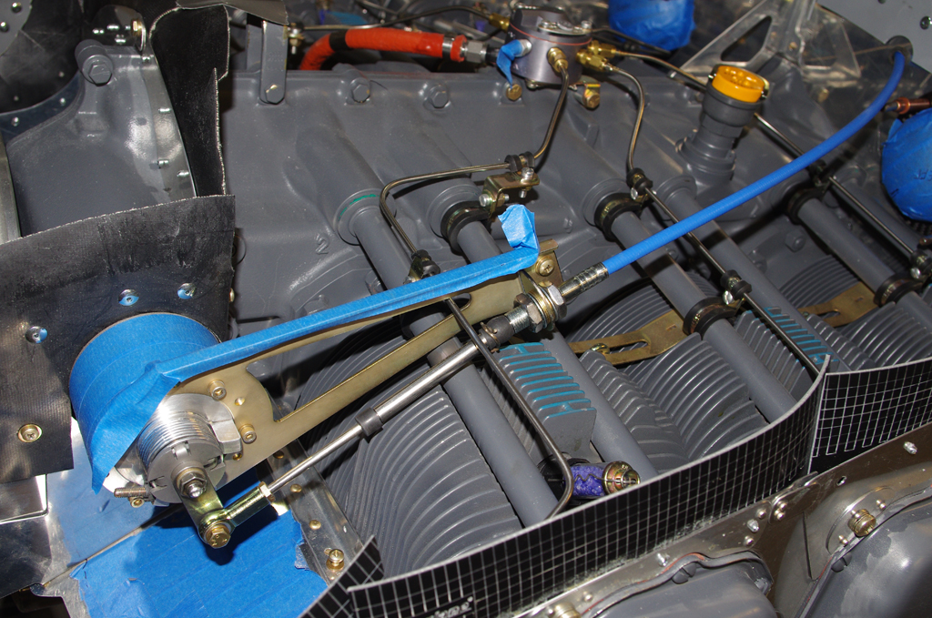
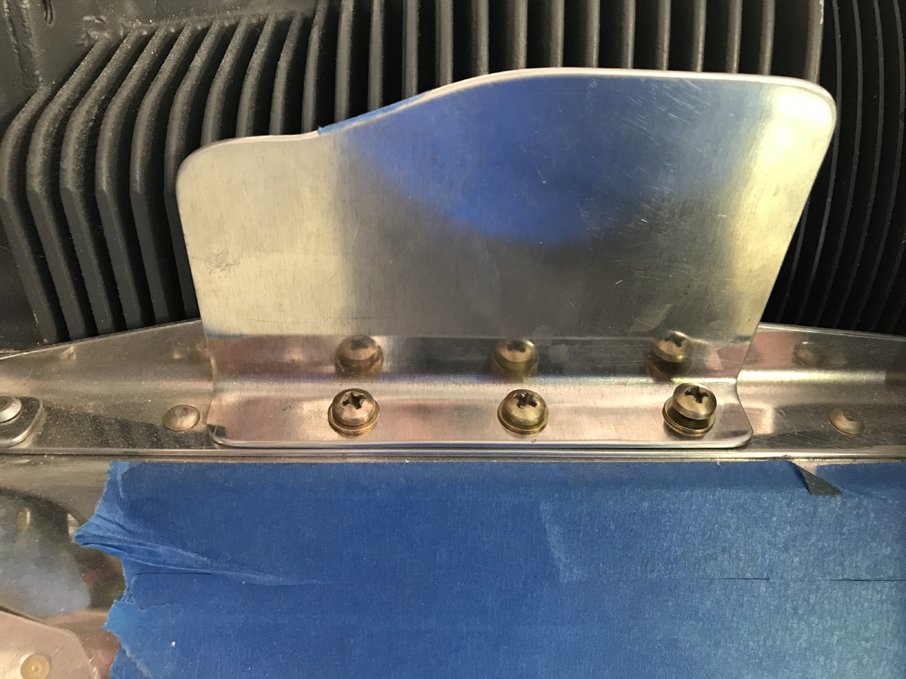 Final connections of the propeller governor cable and bracket adjustments were made. The air dams with their original heights were installed. These were later reduced in size after some initial flight tests were performed.
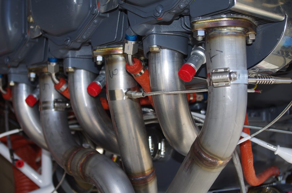
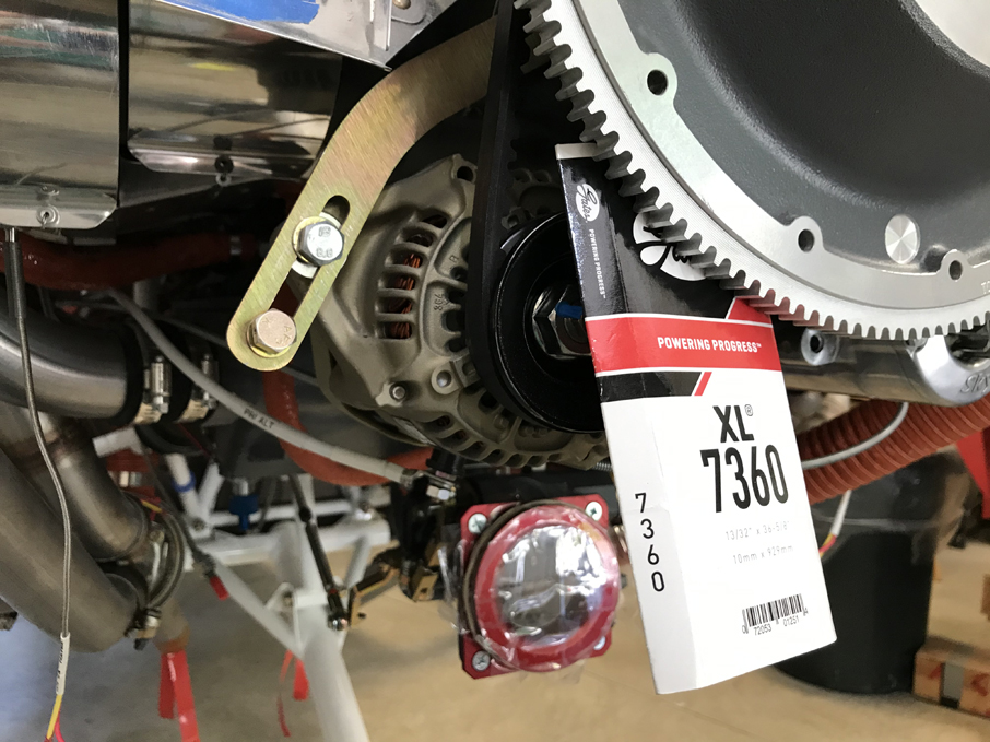 EGT probes were installed in the exhaust manifold, then bundled with their corresponding CHT probe wires. The alternator belt was tensioned and Safe-T-Wired secure.
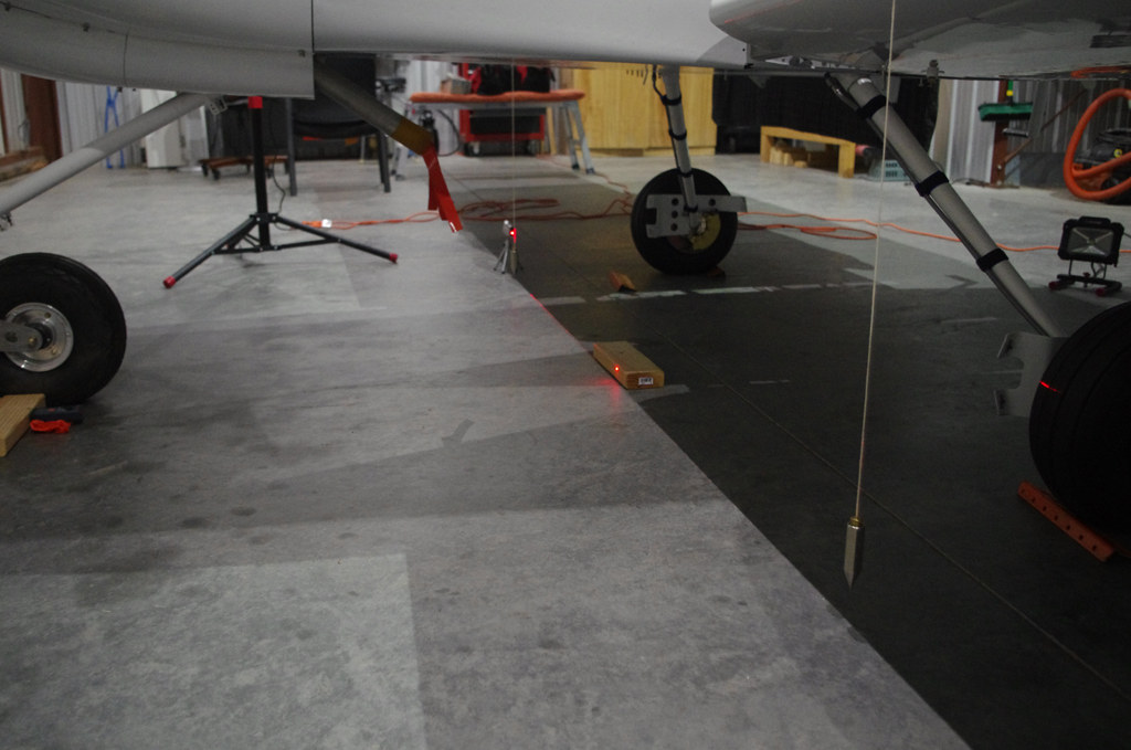
 Measuring the leading edge of the wing provided a reference point for the CG calculations.
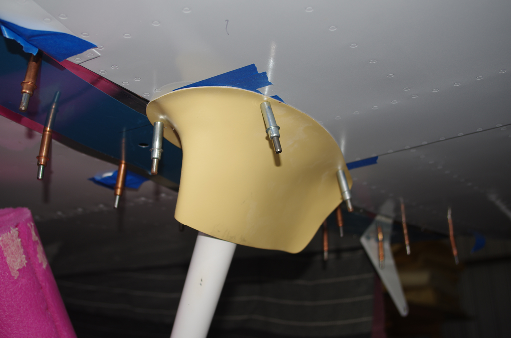
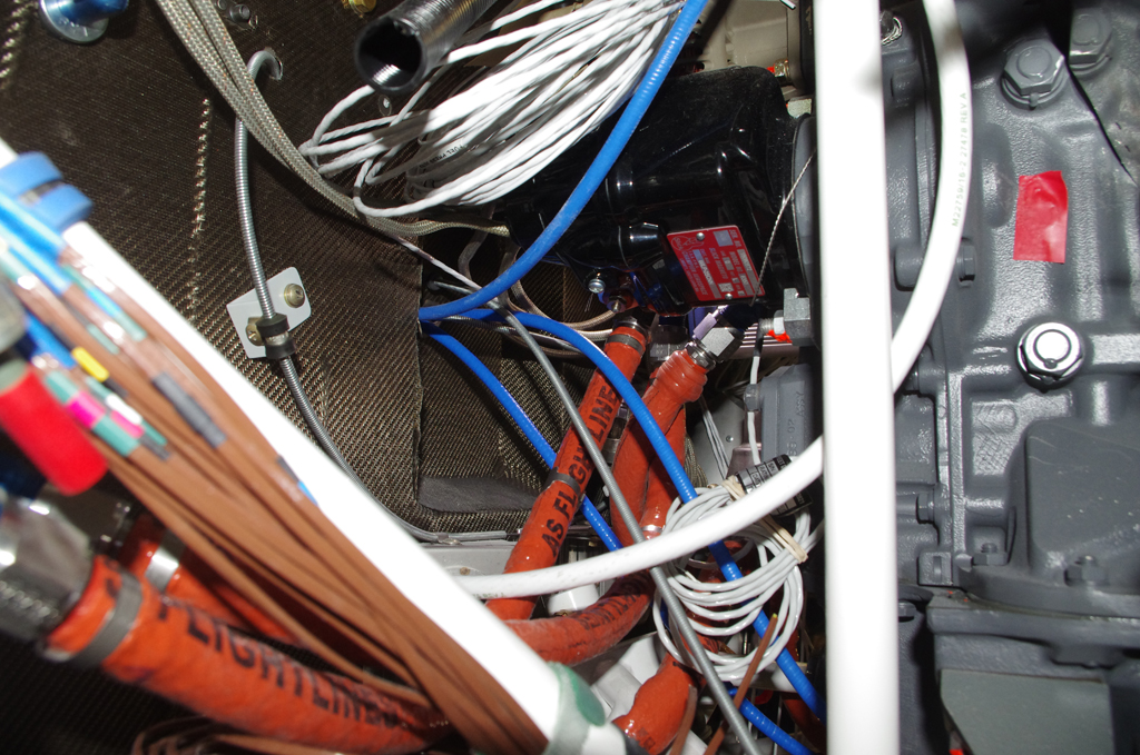
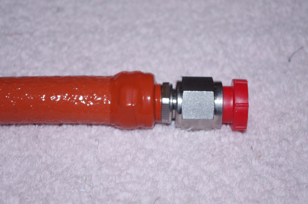
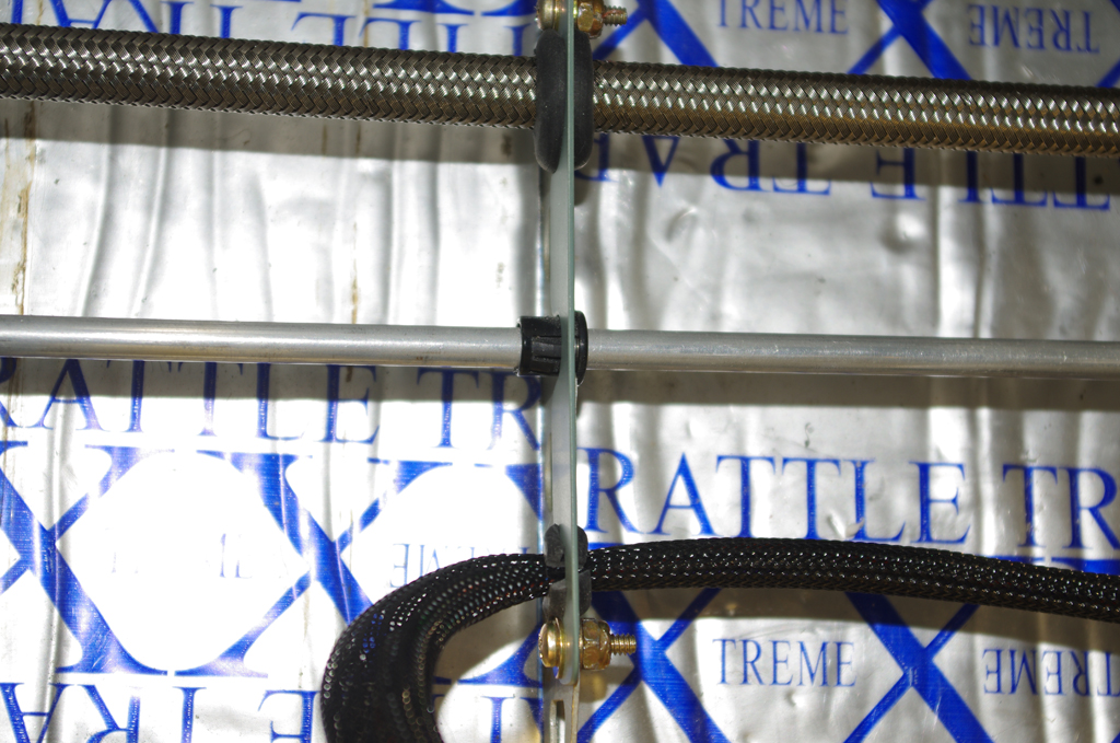
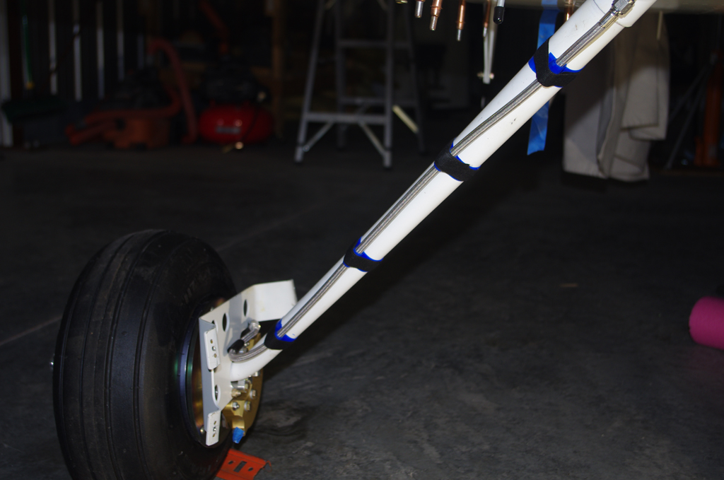 Intersection fairings for the gear legs were initially fit, then later painted and installed after the TS Flightlines stainless braided brake lines.
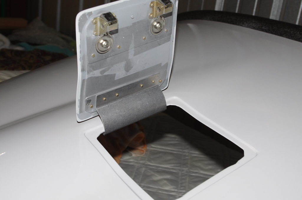
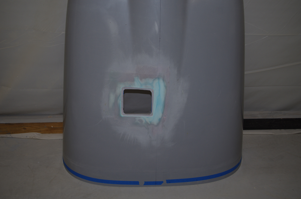
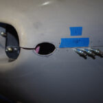
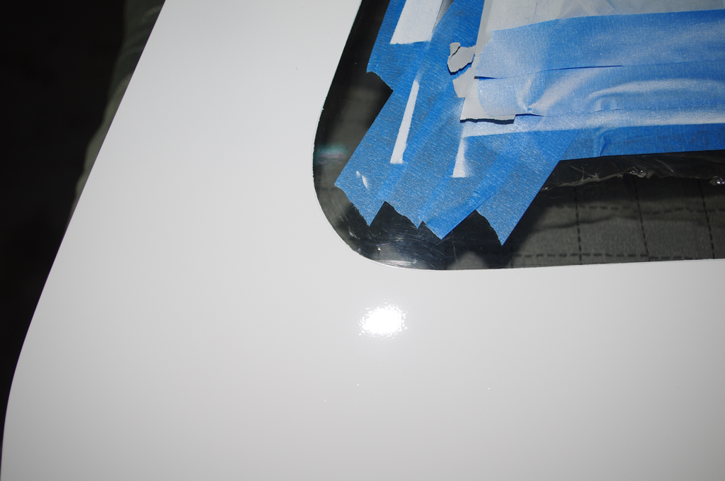
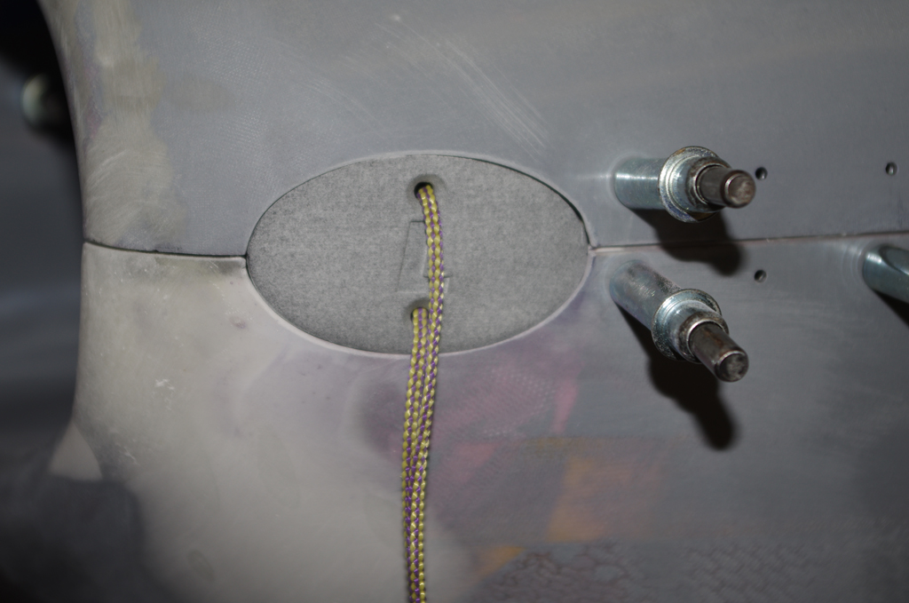
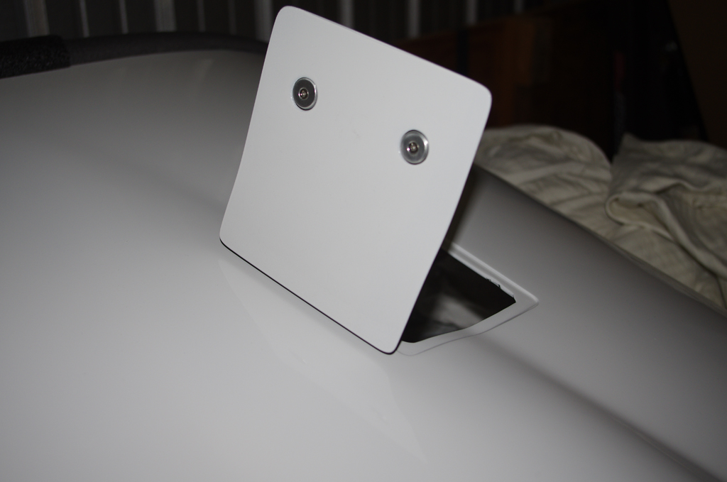 Final installation of the oil door with hidden hinge…
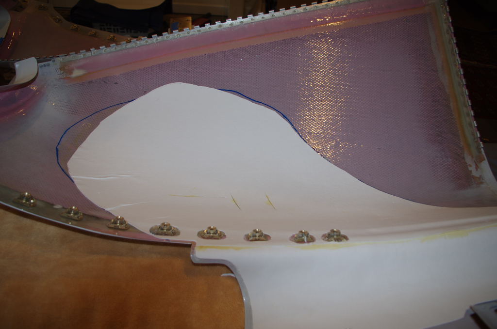
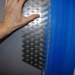
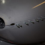
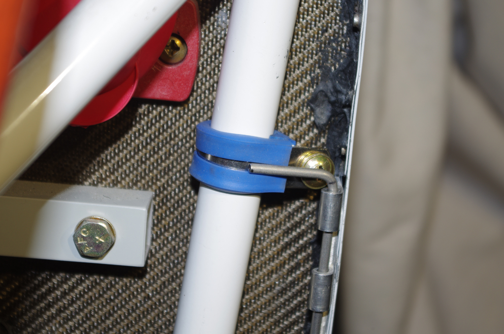 A 1/16″ ceramic mat was contact cemented in the lower cowl, then covered with Vans aluminum heat shielding. This combination should prevent the cowl paint from being scorched by the exhaust manifold heat. Lower cowl pins will be secured against these Adel clamps with tie wraps.
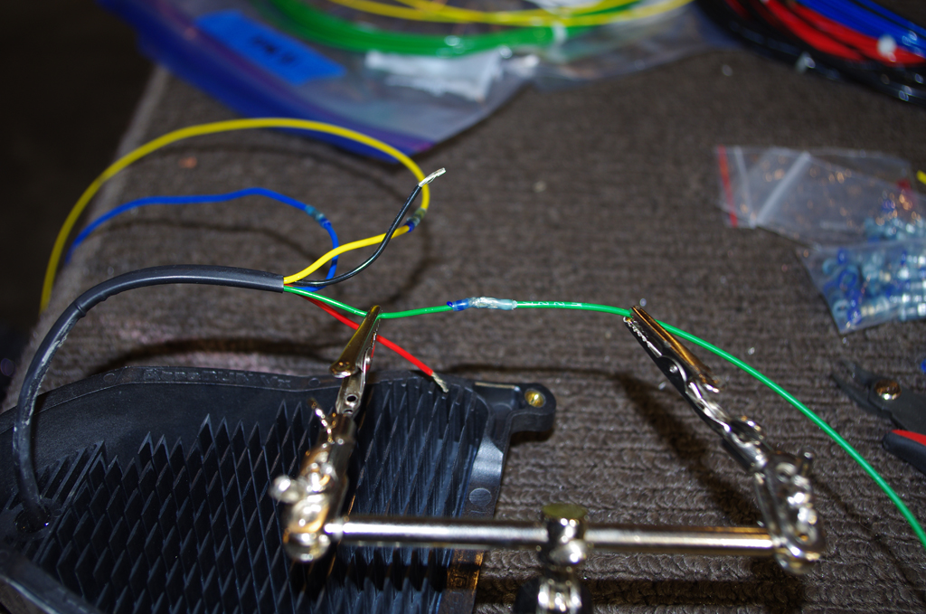
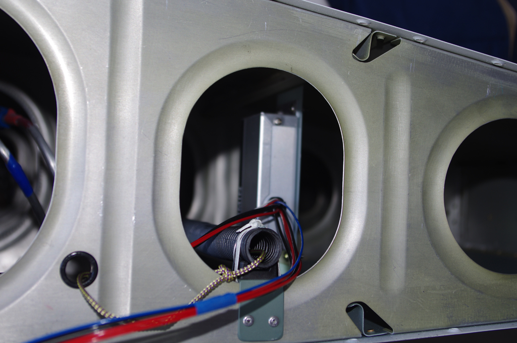 Final wiring for AeroLED VX landing lights were Solder Sealed, then run through conduit to the wingtips.
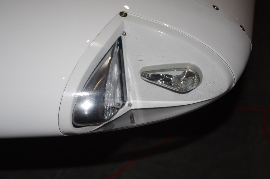
 AeroLED VX landing and NS position lights/strobes…
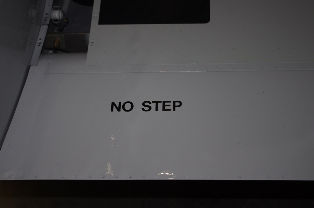
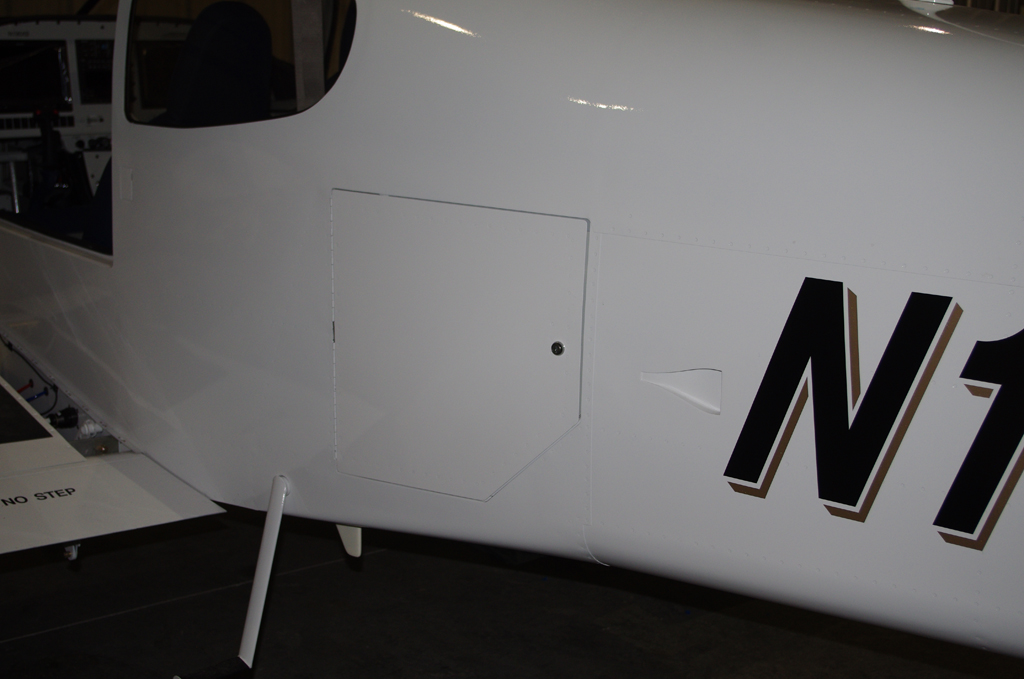
 Decals applied to flaps and doors…
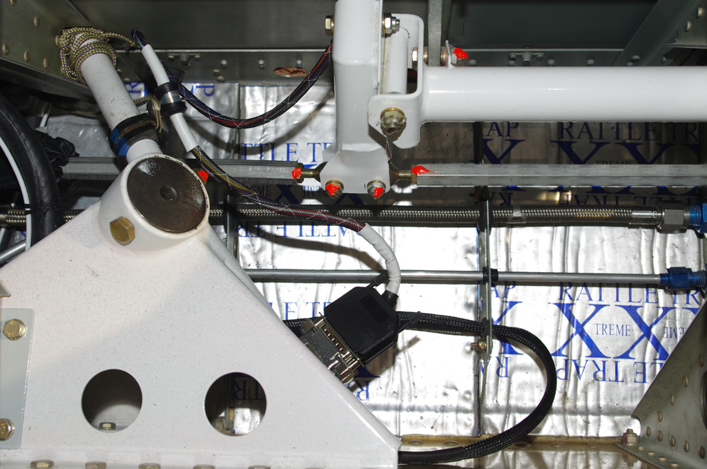
 Wiring from control sticks to system buses used DB15 connections for easy maintenance or removal.
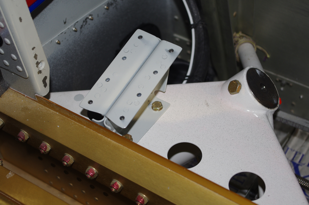
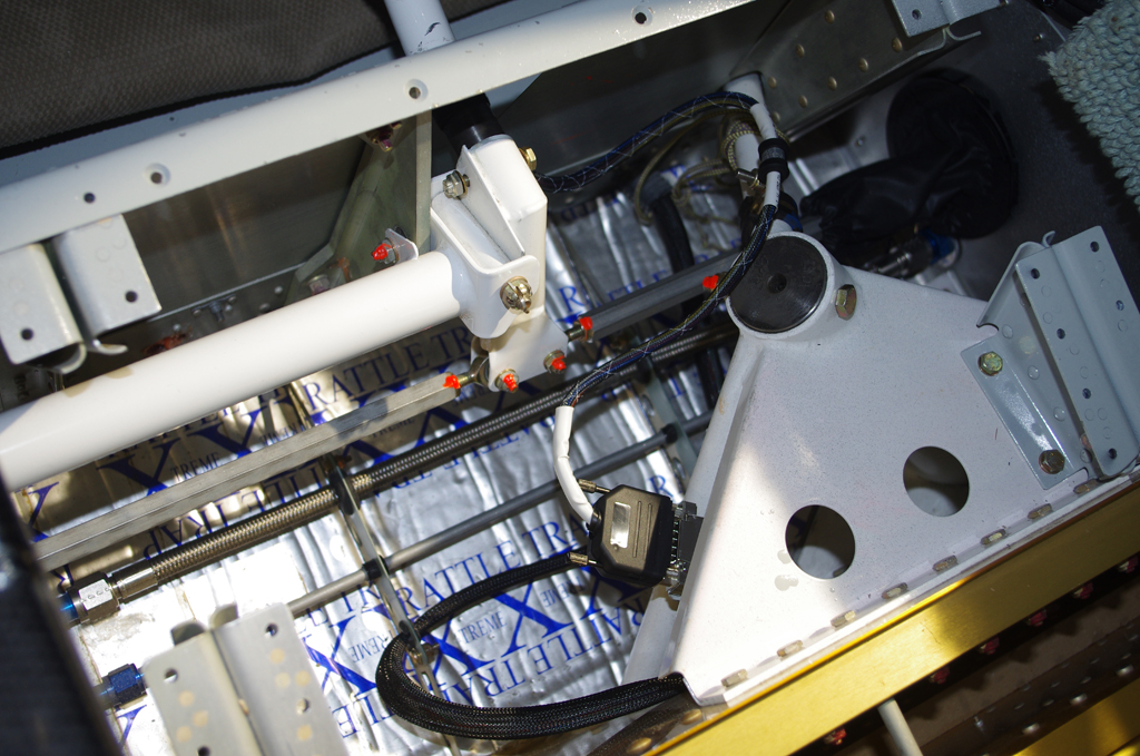
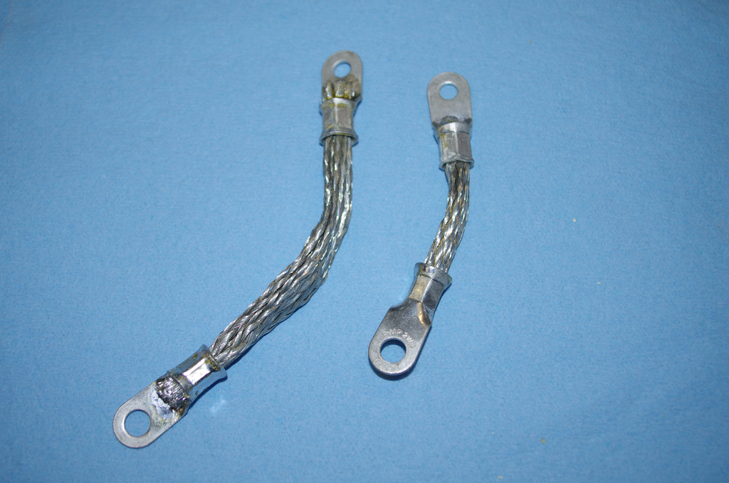
 Ground wires were covered in thick rubber fuel lines to prevent chaffing, then seat pans were installed.
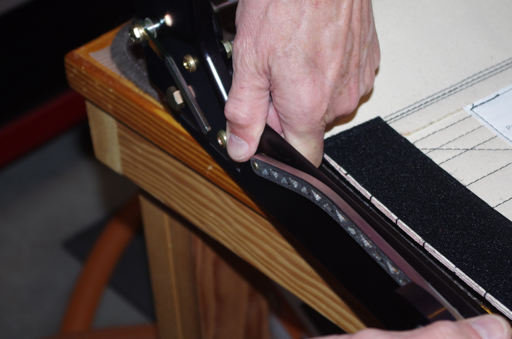
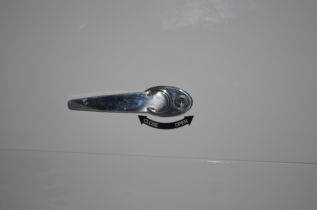
 Aerosport auxiliary seat handles were installed for easier operation. Then final inspection and review of everything to date.


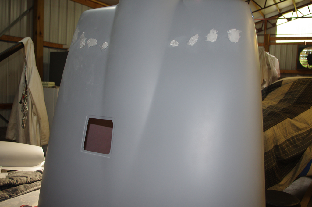


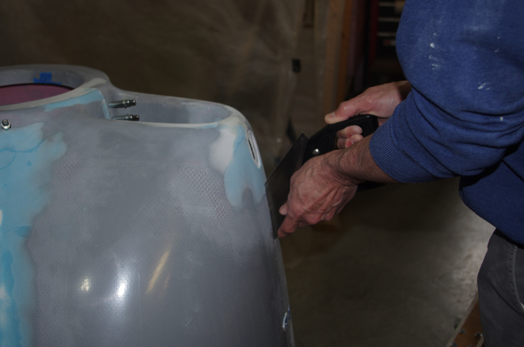


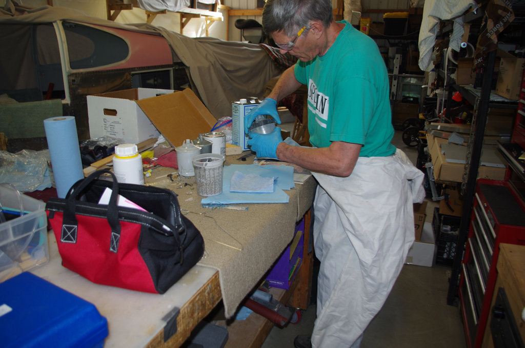
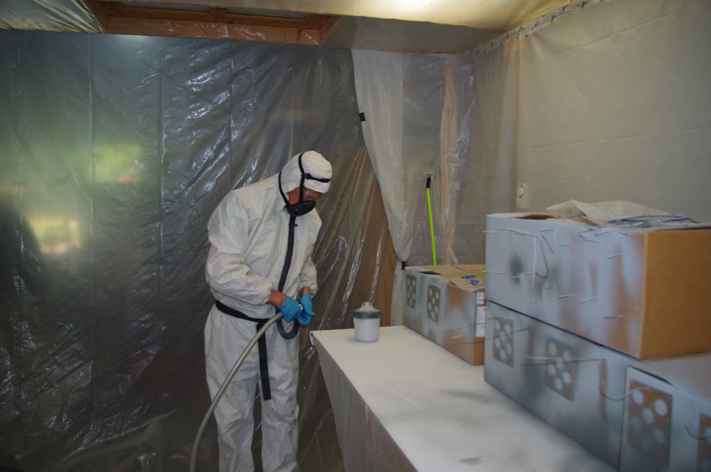

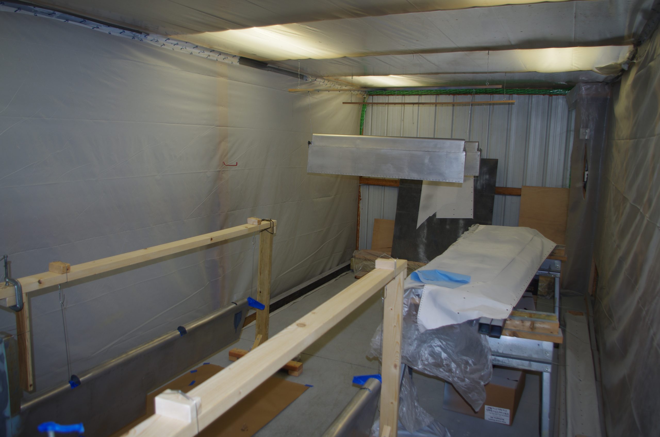
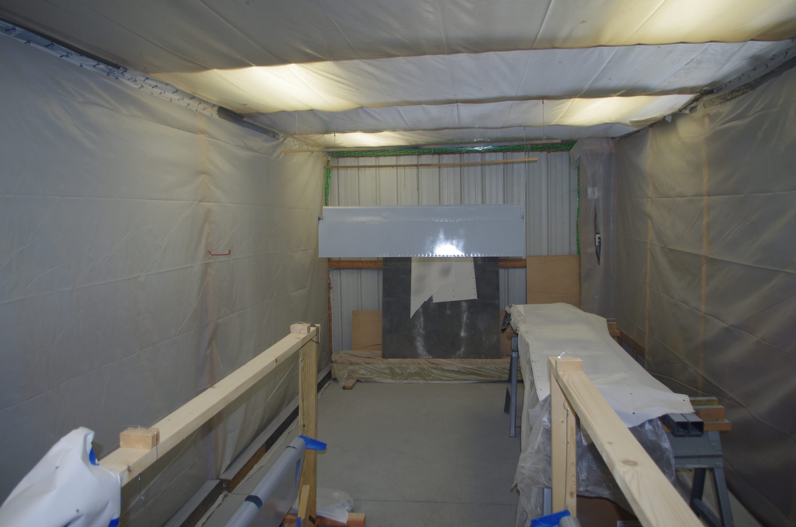
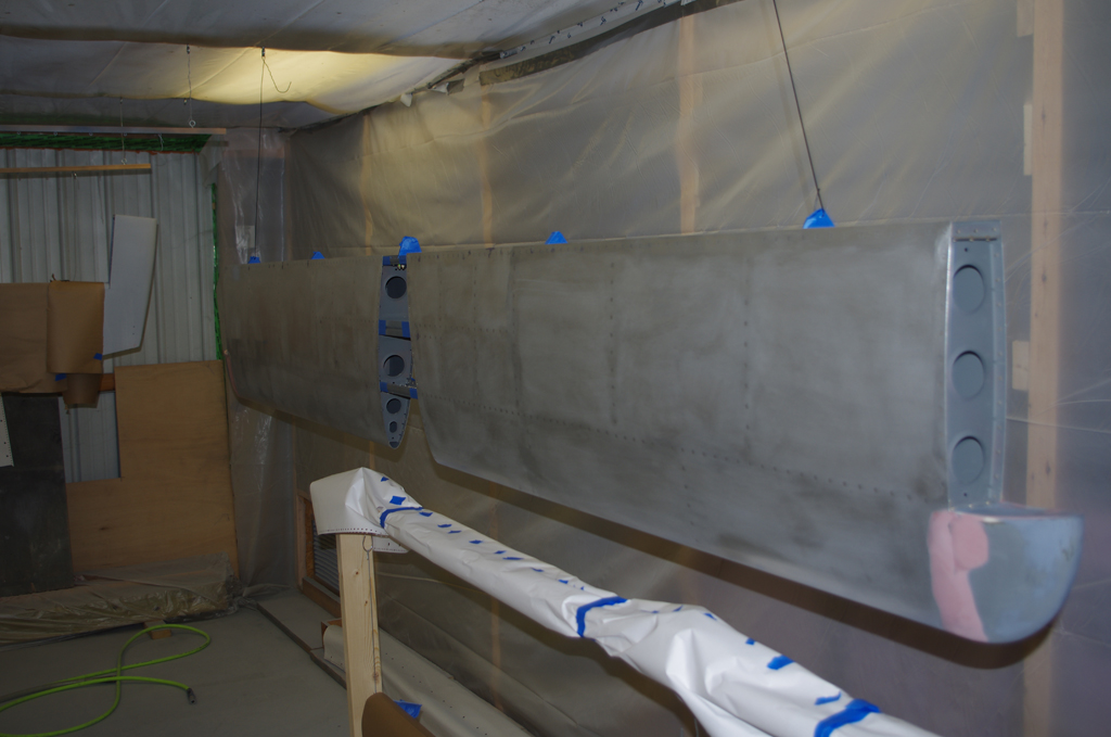
 Preparation steps include using a maroon (=320 grit) Scotch Brite pad in a palm sander to scuff the surface, clean with degreaser, condition with Prekote, then apply primer.
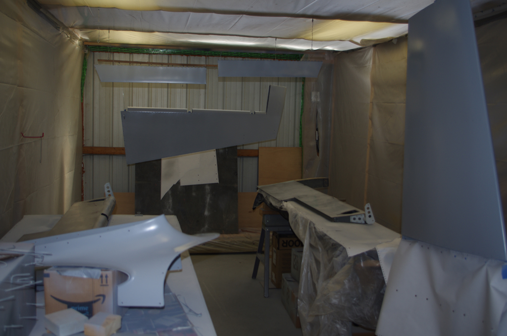

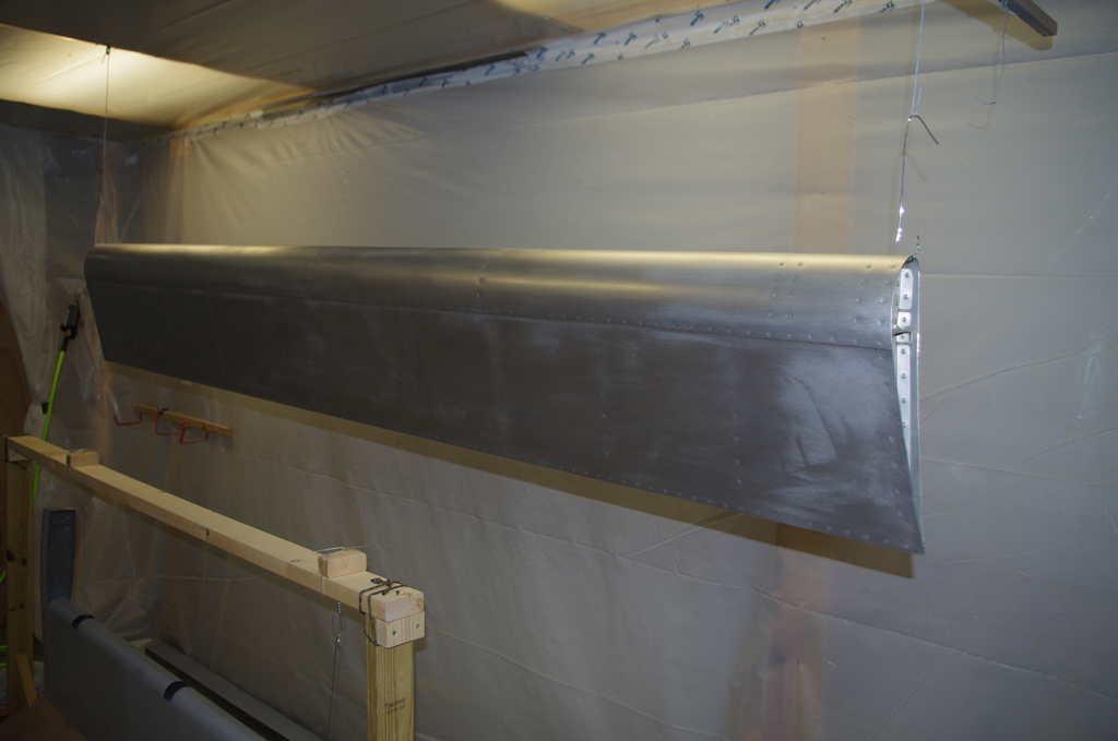
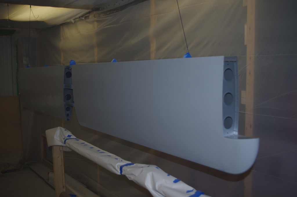
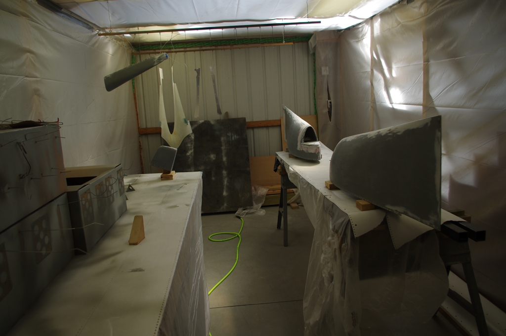
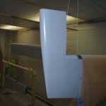 Rudder (close-up and after second prime)(October)