Next section was installing the flap levers and Pittman flap motor from Vans.

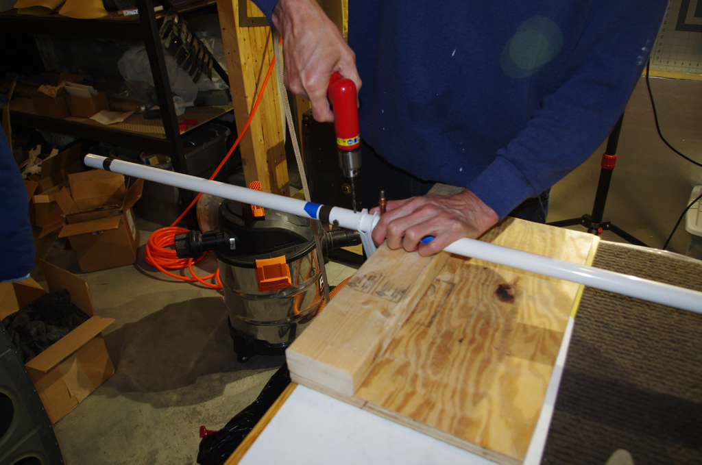 The UHMW (ultra high molecular weight) guide bearings must be relieved to fit under the kick plates in the rear footwell. The various stages of the trimming process are depicted on the left. The right photo was taken during match drilling AN3 bolt holes in the flap crank and torque tubes.

 Proper alignment of the flap crank with the flap horns was achieved by clamping the center crank to the workbench, then using the W-730 Bellcrank Jig to establish the correct angle on the horn. Curiously these call for AN4 bolts, while those for the flap crank are specified for AN3.
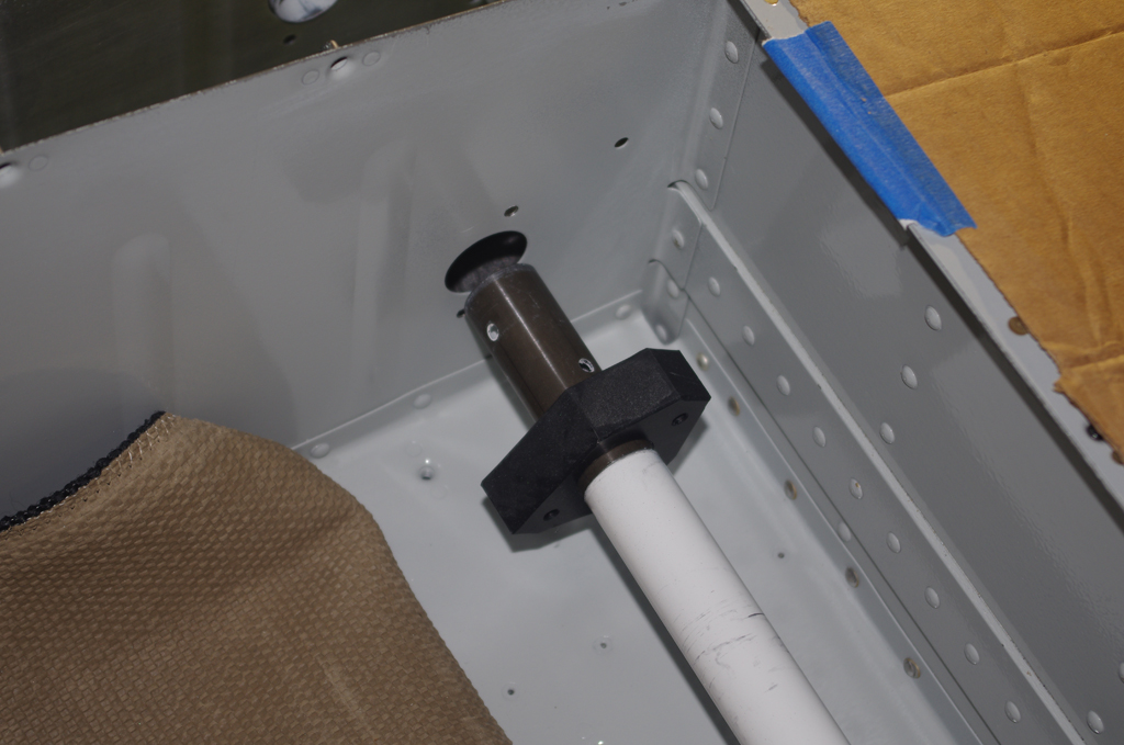
 Insertion of the torque tubes was supposedly achievable from the inside the footwell, but I found pushing through the exterior access holes to be much easier. The quick build exterior holes first needed to be relieved slightly to prevent binding on the torque tubes.
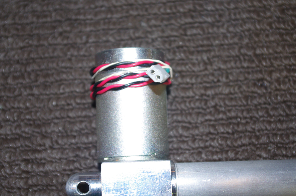
 The flap motor comes without an electrical connection. The left picture shows a Molex 18-24AWG connector crimped into place. The wires near the connector are held together with heat shrink. The flap crank with UHMW bearing are shown on the right.
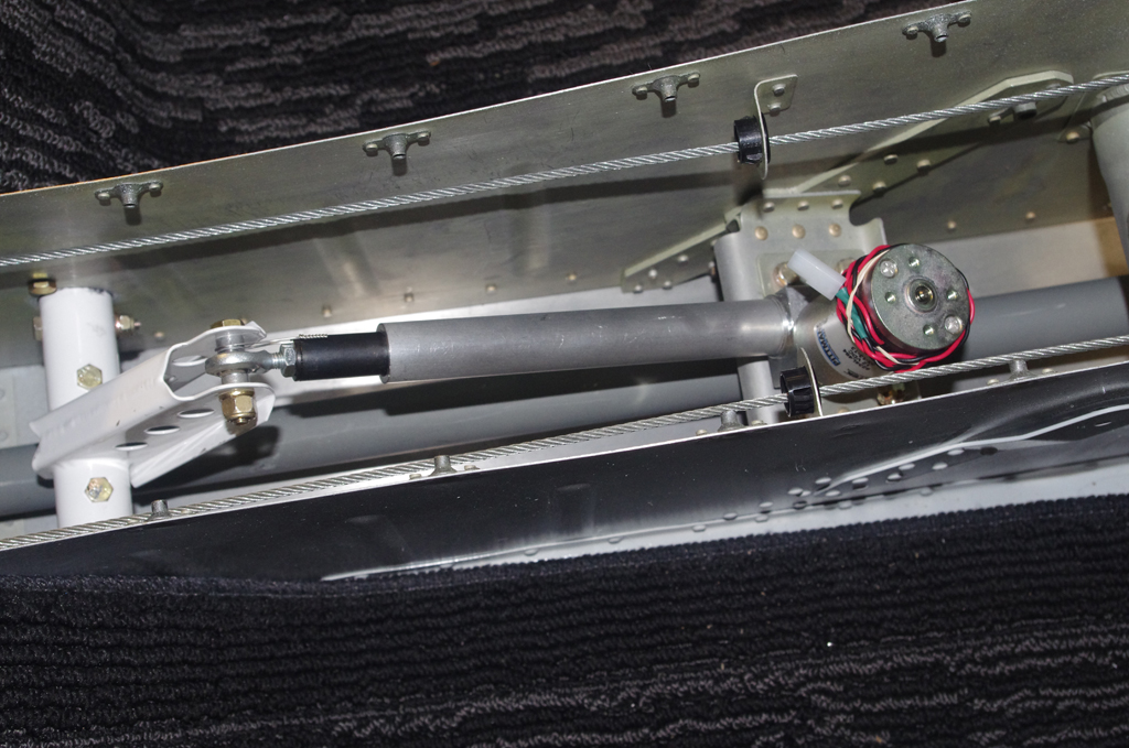
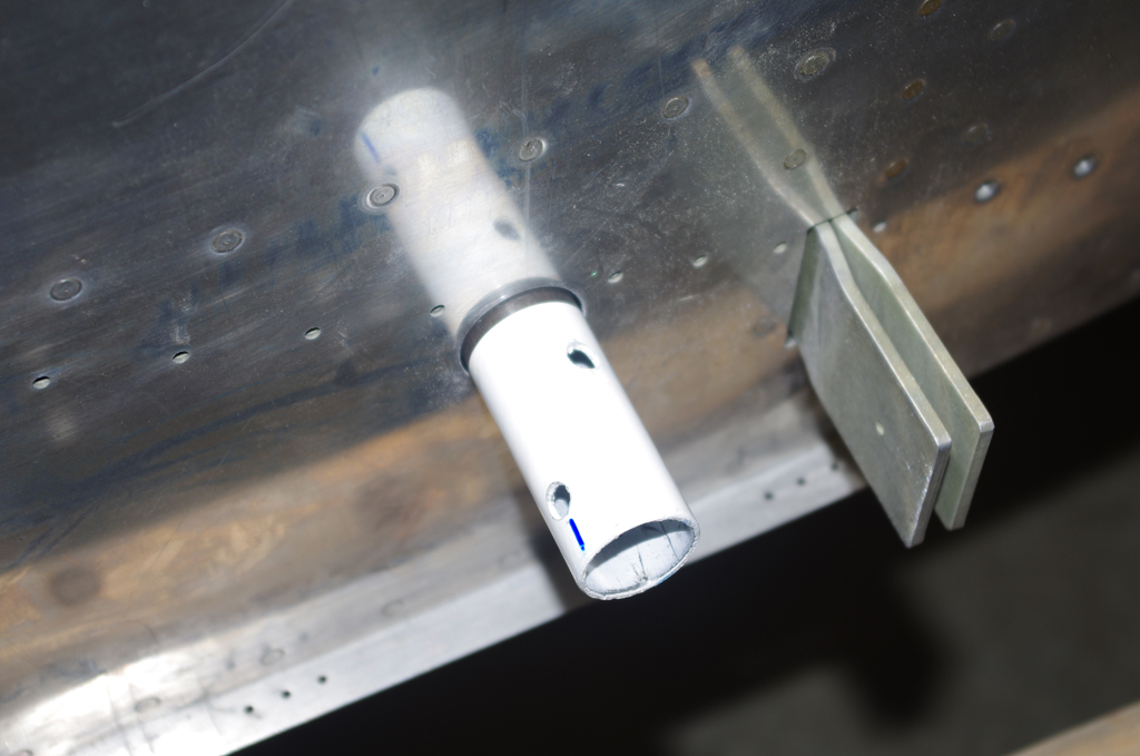
 These photos show the final configuration of the flap motor to flap crank, plus a close-up of safety wire around the pivot point. It was a slow, tricky job to drill a 1/16″ hole in the motor pushrod. The final attachment of the flap horns will be performed after the wing root area is primed and painted.
 A custom flap position sensor mount is fabricated for a Ray Allen POS-12 device. More on this later…