The 2019 holidays saw plenty of shop time for plane work with continuation of a variety of wing preparations.
PITOT SYSTEM
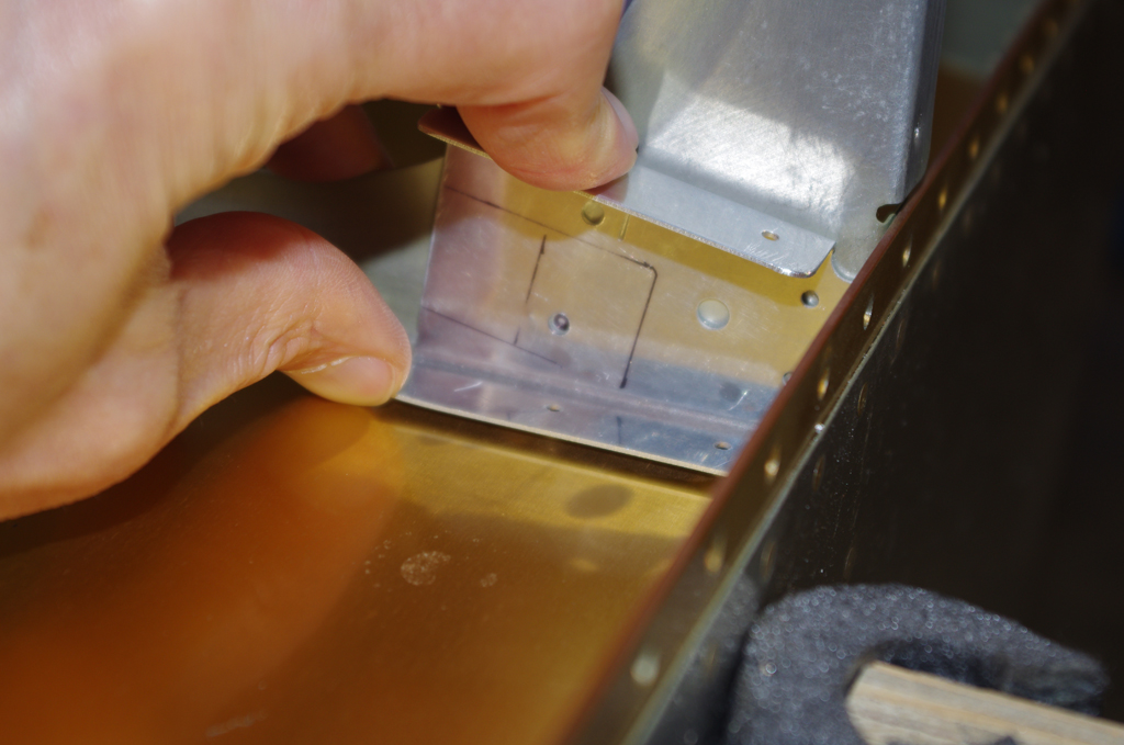
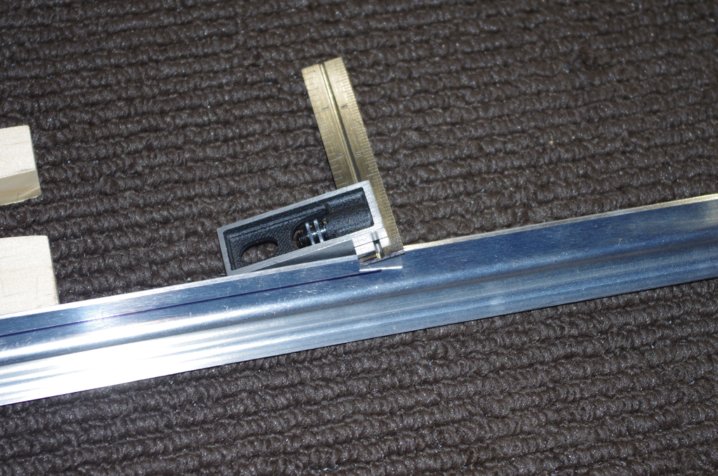
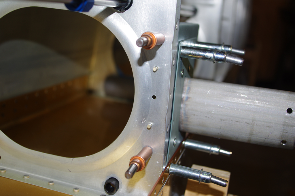
 The pitot and angle of attack (AOA) aluminum tubes near the wing root were flared to accept unions-to-plastic-tube conversions. Note the 37 degree angle and coupler nut are dry fit, no need for lubrication on these pneumatic AN fittings.
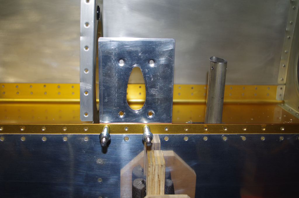
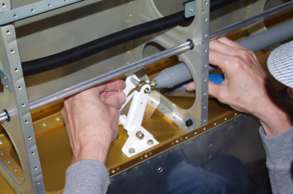
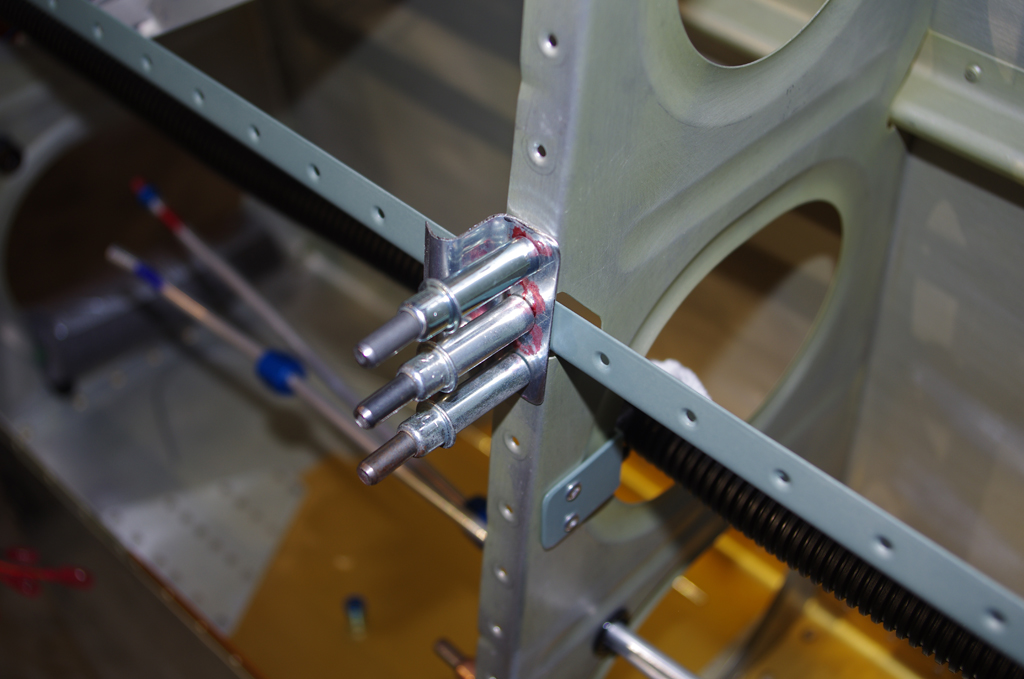
 The pitot mast attachment bracket (fabricated in previous posts) was riveted onto the second to last wing rib. The pitot probe tubes were then bent to about a 90 degree angle.

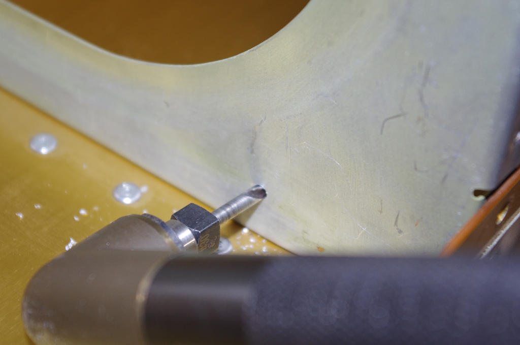
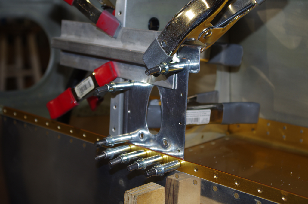
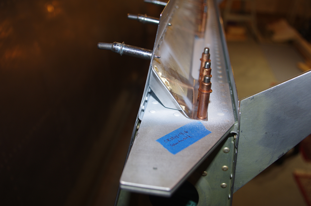
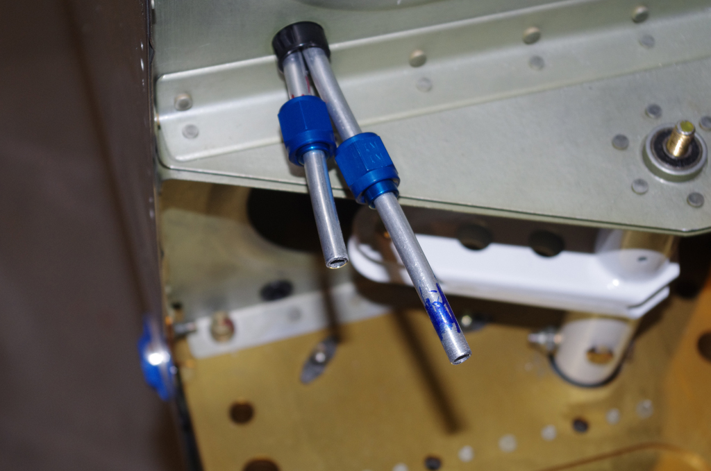
 The aluminum tubes at this end of the wing were also flanged using a Parker Rolo-Flair tool. The red and blue markings are colored Rescue Tape. Blue for the pitot line, red for the AOA tube.

 The flanged tubes were then arced backwards with an Imperial 368-FH bending tool. This configuration now allows connection of the pitot lines through the wing ends. After the skin is permanently riveted the access will be limited.
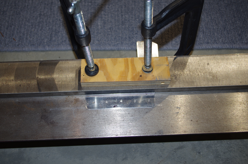
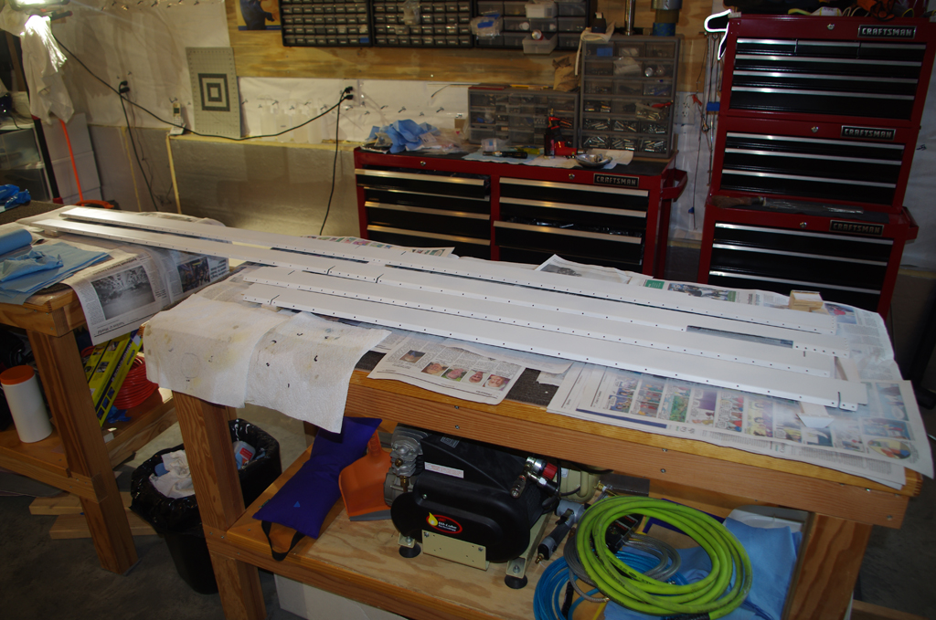
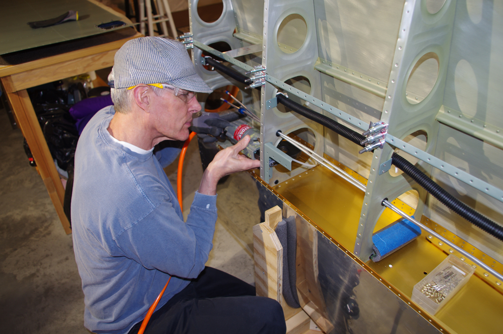
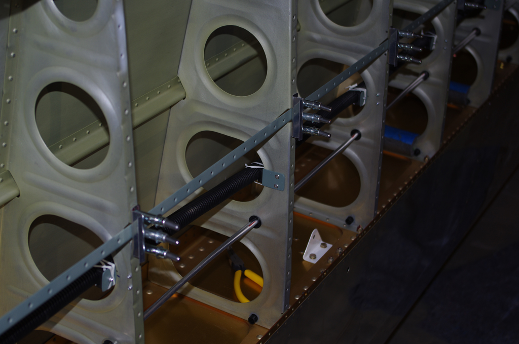 Once the pitot tubes were finished, then the nylon wiring conduit was cable-laced into position. A few custom jigs were made to hold the J-channel stiffener in perfect alignment with the wing ribs. This stabilized the rib orientations while the conduit was laced.
WING TIPS

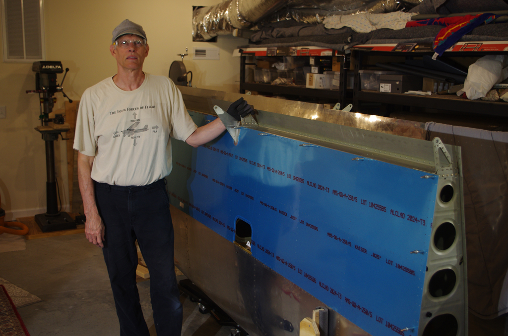
 To finalize the wing tip geometry the flaps and ailerons were attached and placed in the “neutral position”. This is establish using a combination of the Aileron Bellcrank jig and moving the flaps to the upper, hard stop position against the rear spar. The final angle was adjusted to 3 degrees with a few thin shims. The red Gust Lock in the photo holds the flaps/ailerons together at the same angle.

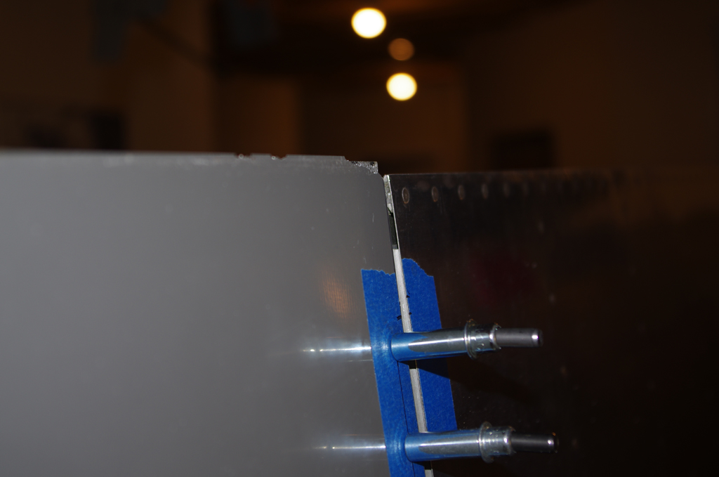
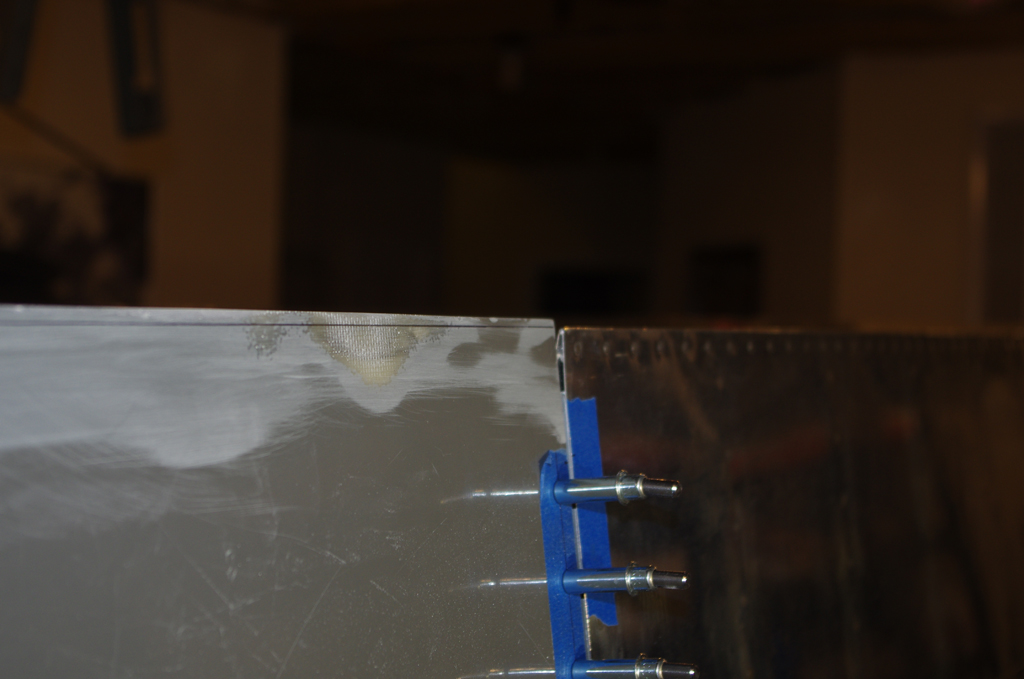 Here are the before and after pictures of the final wing tip alignment. The steps described below were needed to make the corrections.
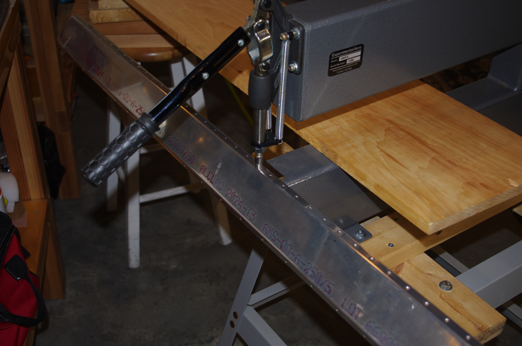

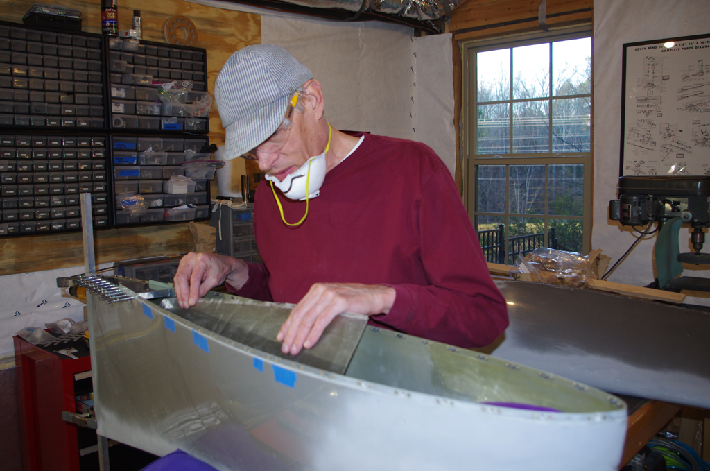
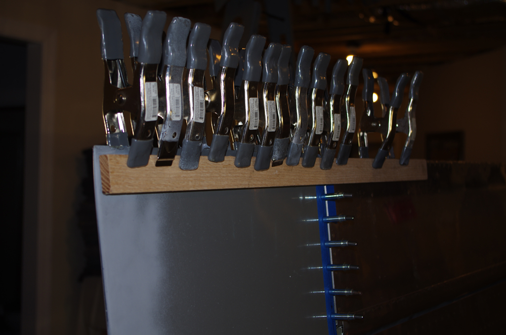 First the rear edge of the wing tip was separated with a saw. This allowed the end panels to slide against one another. The wing rib holes were drilled to even spaces. The split wing tip was then attached to the wing, and the wing rib progressively clecoed from the front edge toward the rear. Colloidal silica resin, a straightedge and spring clamps were used to align the rear edge with the neutralized flap/ailerons.

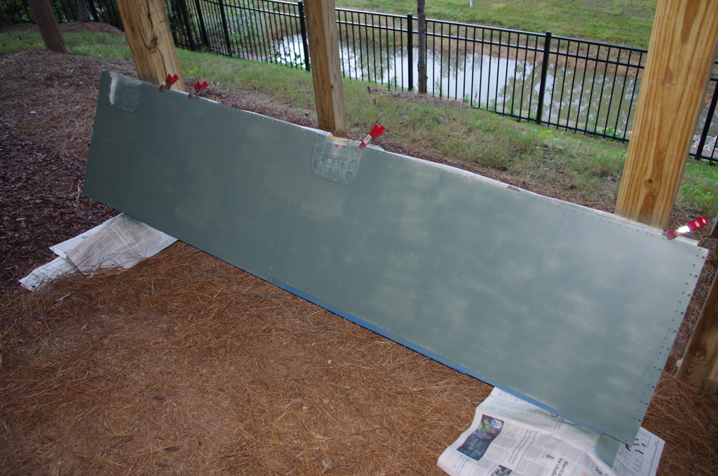
 The final edge was allowed to cure for 48 hours. Then the overage from the wing tips measured. Eventually this extra material was removed (more on this in a later post). The overall outcome was very satisfactory.
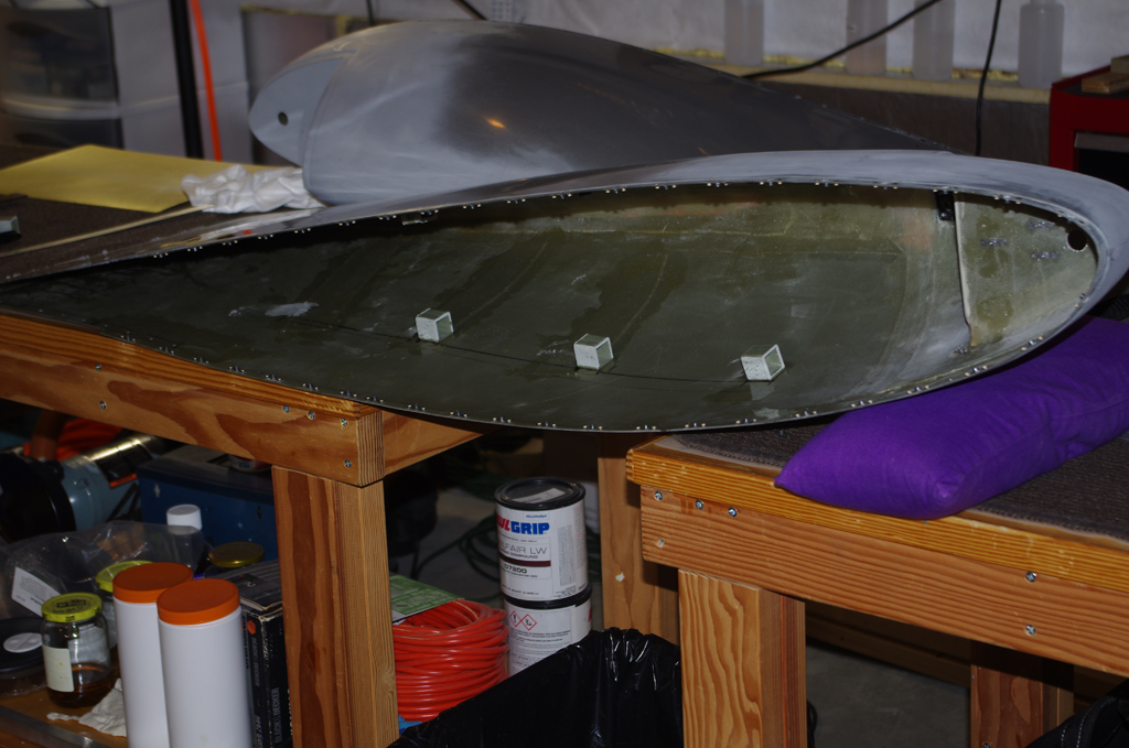
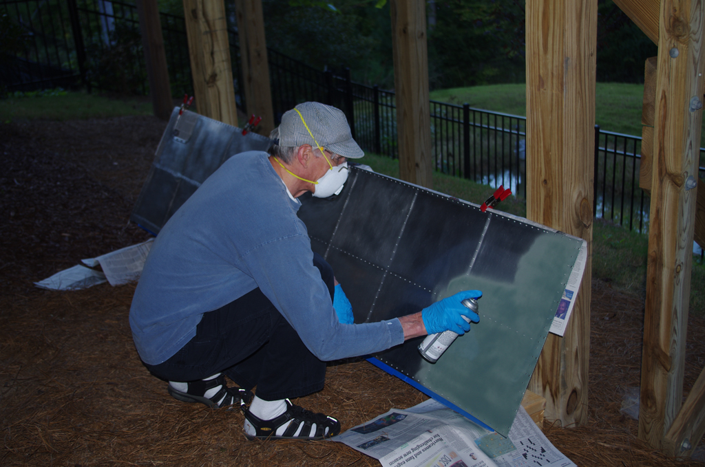
Another addition to the wing tips was a stiffener rib. This helps prevent “oil canning” in flight due to air pressure on the wing tip surfaces.
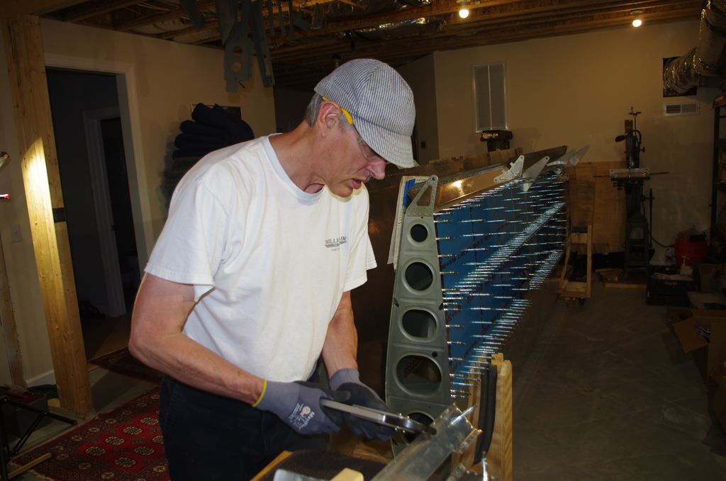
WING SKINS
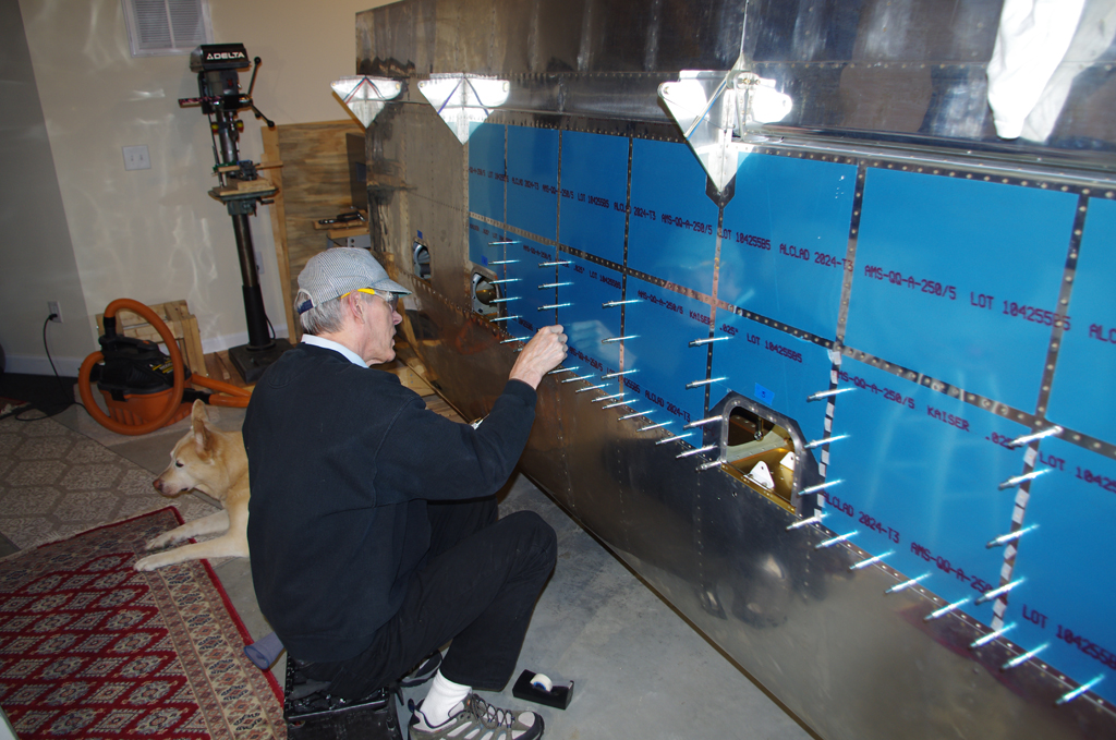
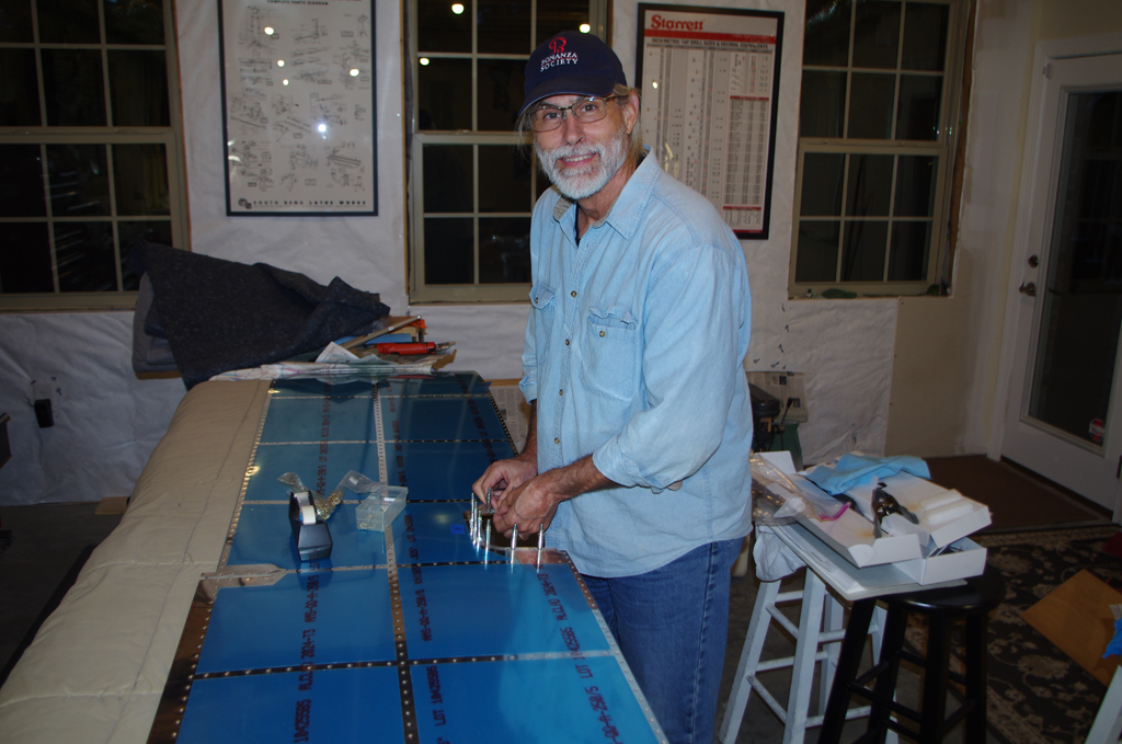
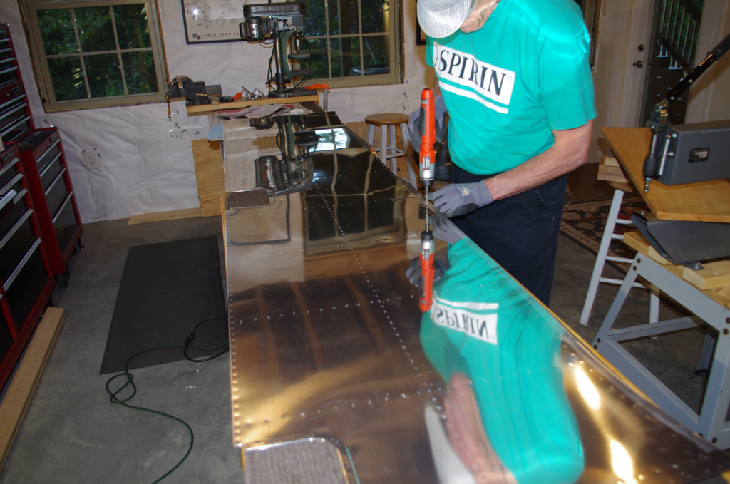
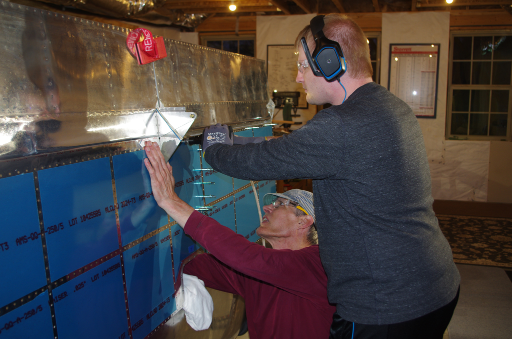 With the wing tips nearing completion and all the other mechanical elements in place, time to start riveting the lower skins. This was a time consuming, two person effort. The right wing took about 10 hours to finish. We are just starting on the left wing now.