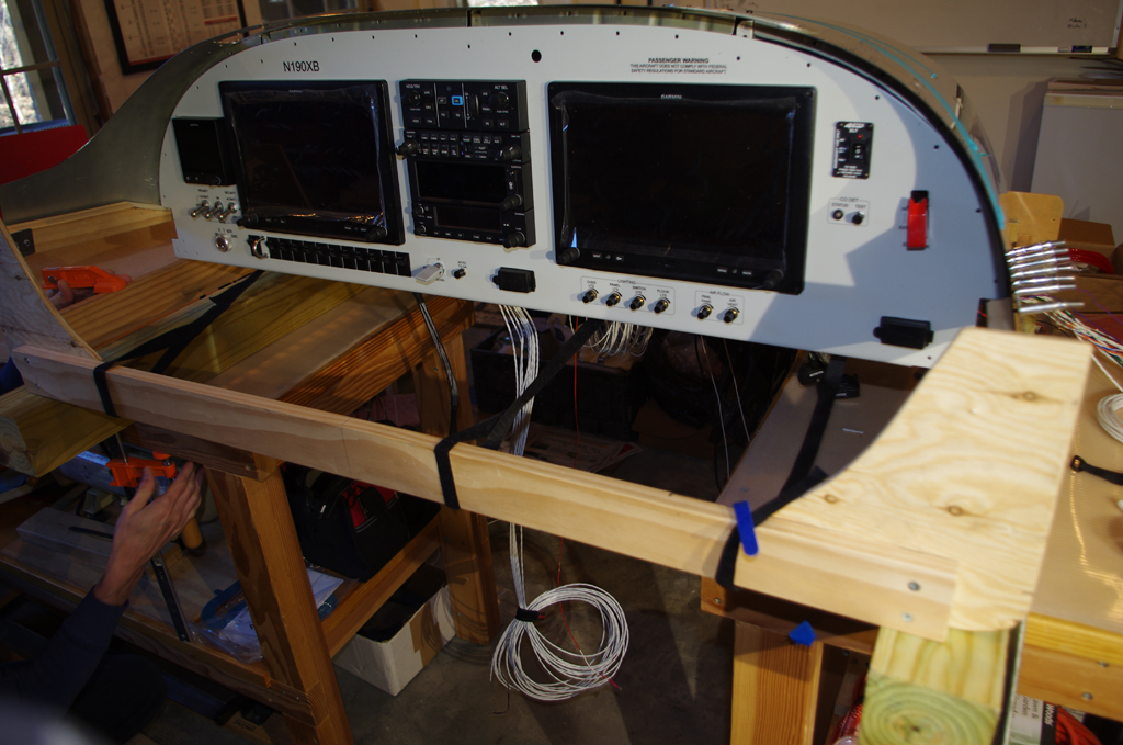
Now that the instrument panel had passed basic bench testing, it was time to permanently attach to the fuselage and firewall.

 The metal surfaces were treated with SEM Self-etch primer.
 The fiberglass reinforcement plate prepared in previous posts was then added to help strengthen the grips.
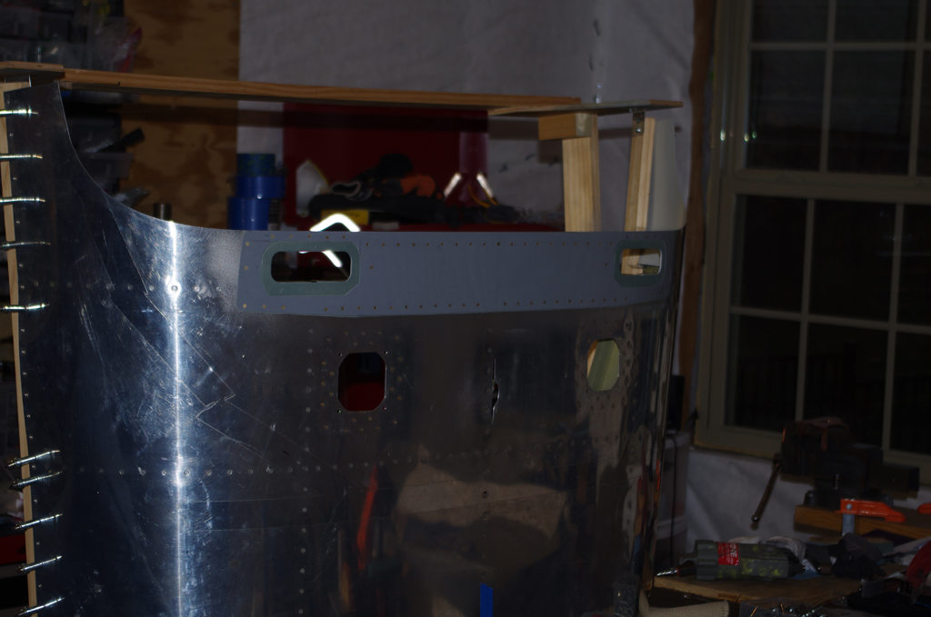
 The underside portion of the dashboard was painted in the standard interior 707 Boeing grey color.
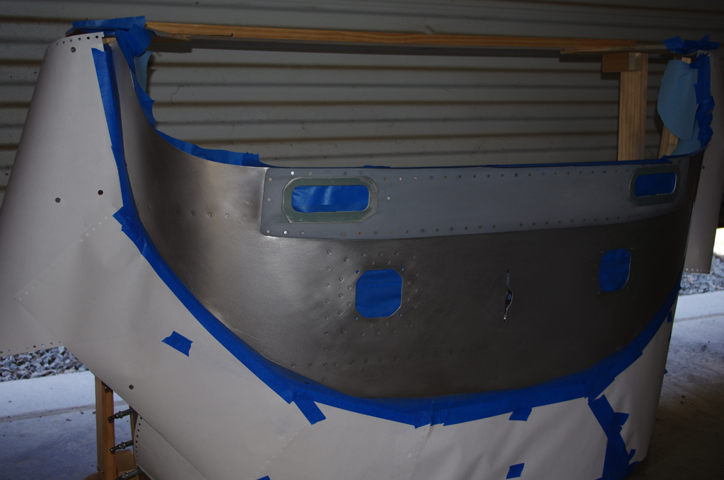
 Here the upper dashboard / glare shield area is taped and prepared for painting. While the intention is to later cover with some fabric material, the flat black base coat could be used AS-IS in the meantime.
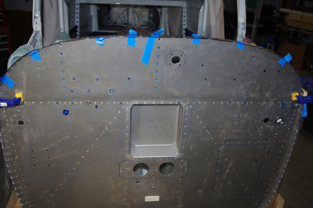
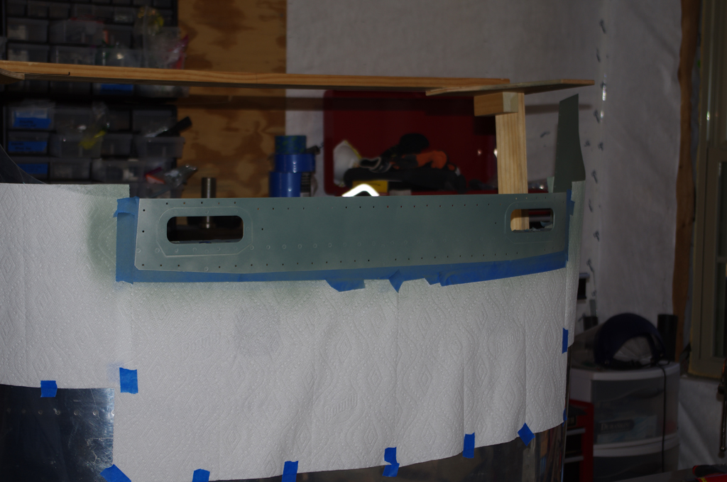
Now that the upper dashboard was ready, the firewall was prepared for final attachment. Here a 4-mil acrylic sheet is taped to the firewall. Holes were traced using a blue Sharpie pen. The acrylic template was used for precisely cutting LavaShield insulation material. (more on that in a later post.)
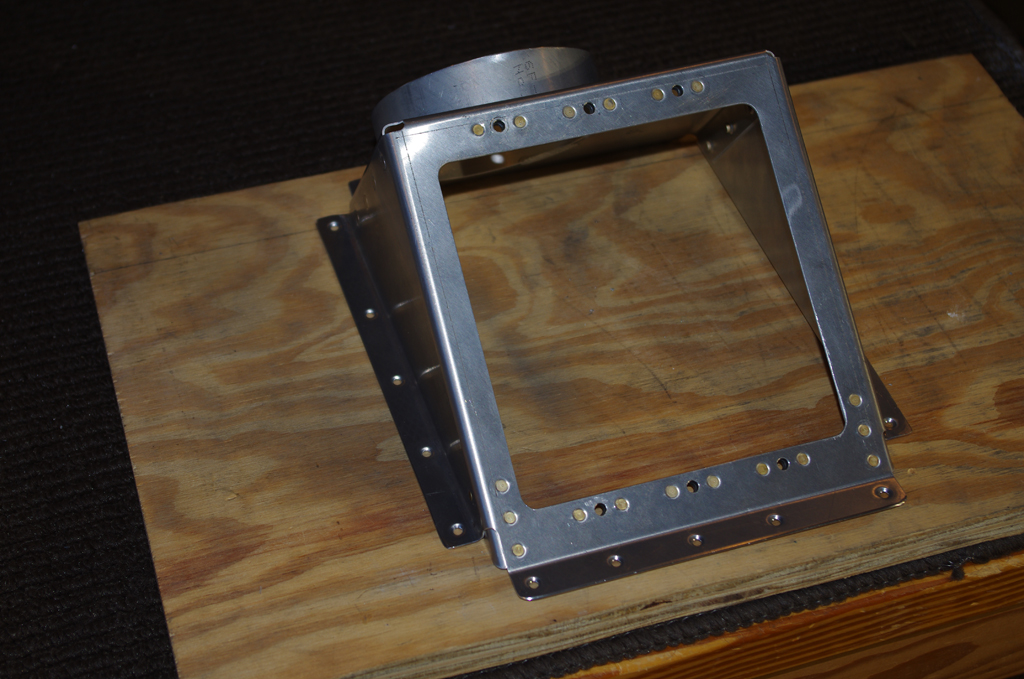
 The oil cooler bracket was riveted together and nutplates applied. The completed unit was then riveted onto the firewall with AN470AD4-4 rivets.

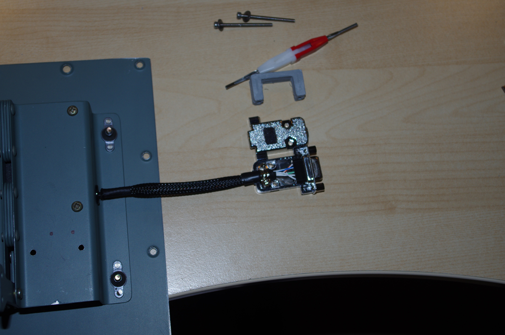
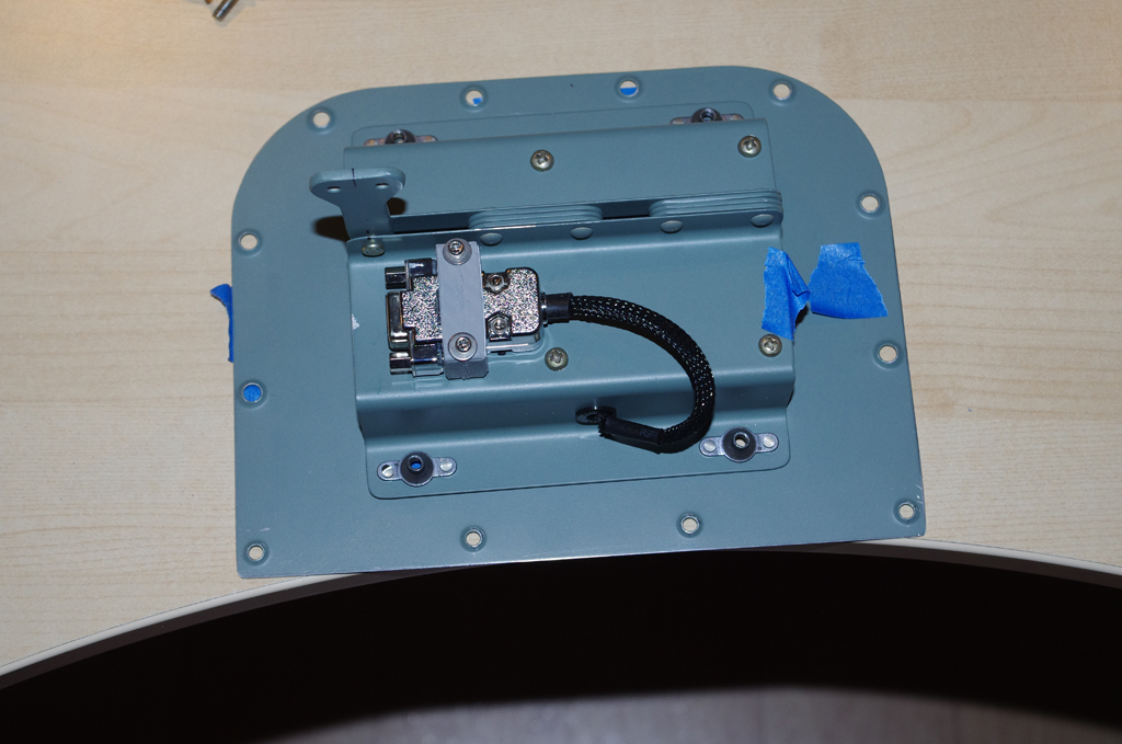
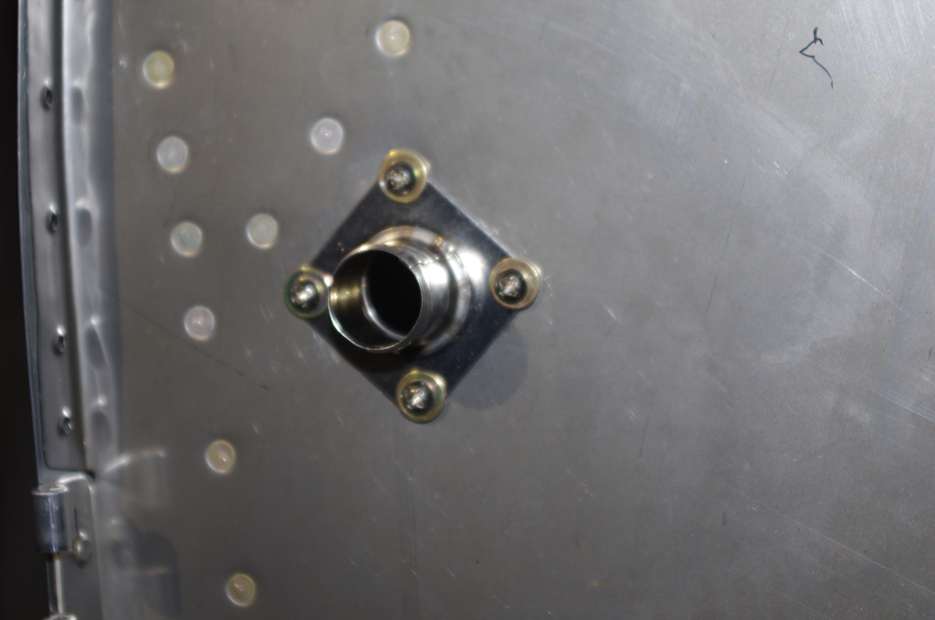
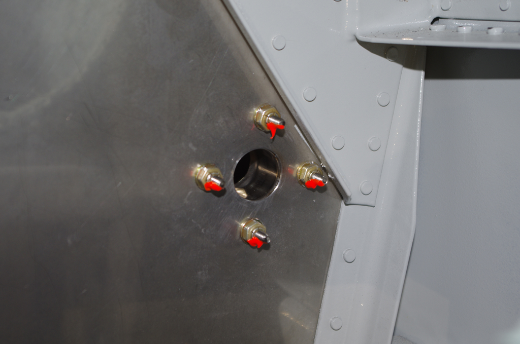
 The main wiring pass-through in the upper center of the firewall is 1″ diameter stainless steel. The photos show from the firewall side and the cockpit side. This location will contain most of the general sensor wires (fuel pressure, oil pressure, oil temperature, tachometer,…), plus starter contactor, Surefly and Slick ignitions, and voltage regulator connections.
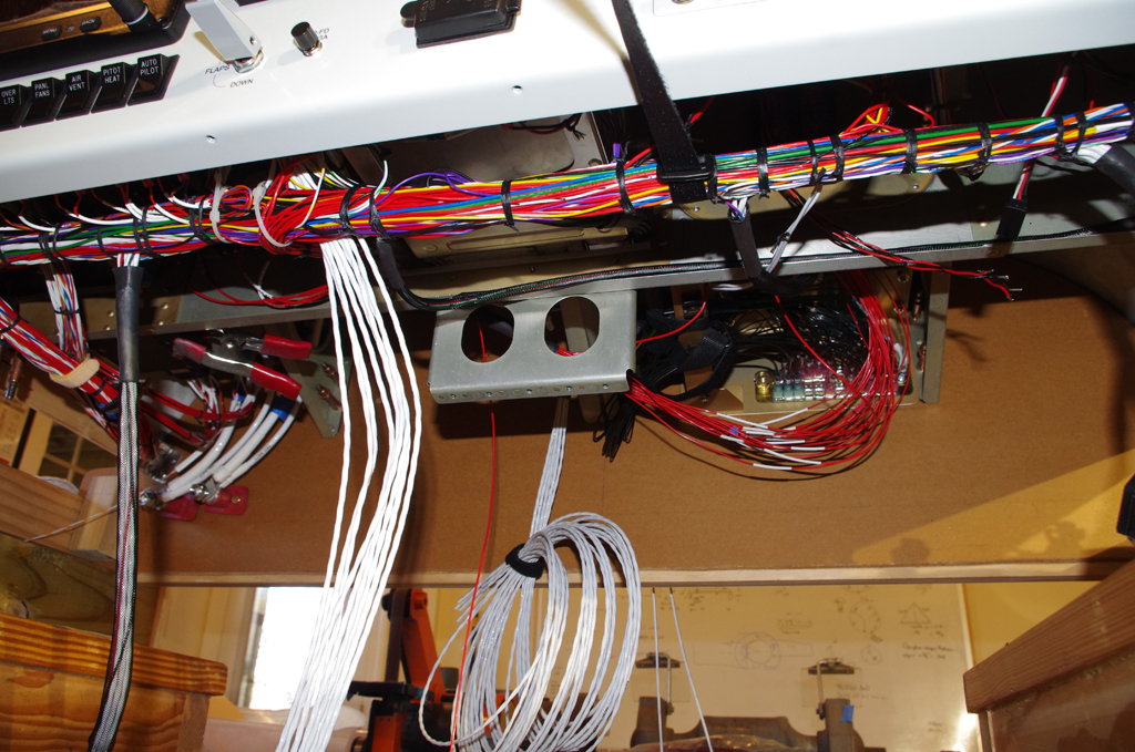
 The smaller 3/4″ pass-through on the far right side will house the CHT and EGT sensor wires.

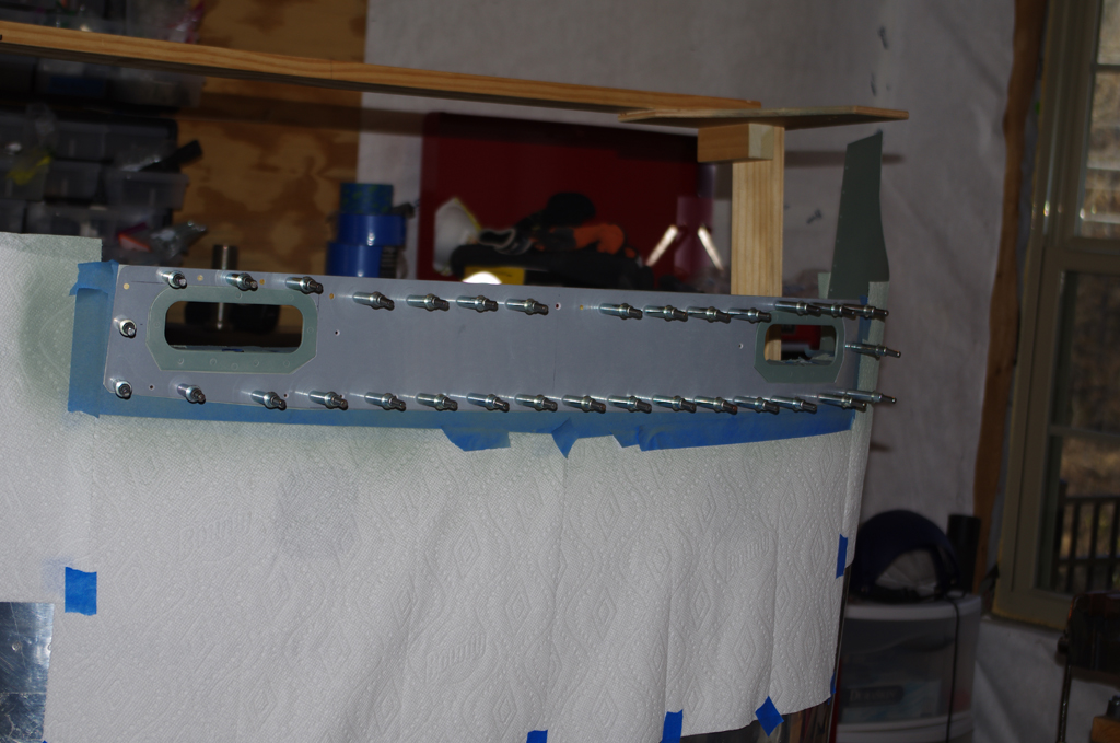
Here the upper fuselage / dashboard unit is clecoed onto the main fuselage.
 The longitudinal ribs were connected to the firewall with CherryMax CR3212-4-2 rivets. Using structurally rated pull rivets was much easier to install than bucking, plus just as strong.
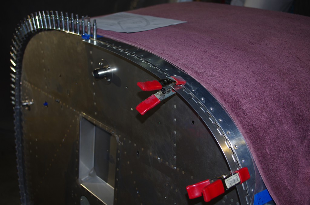
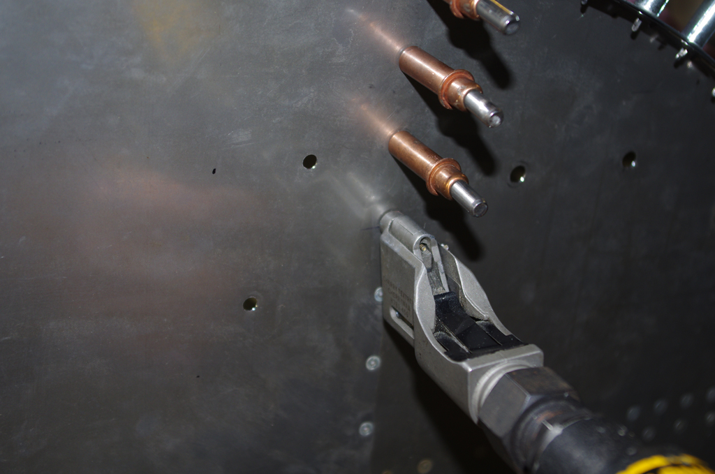
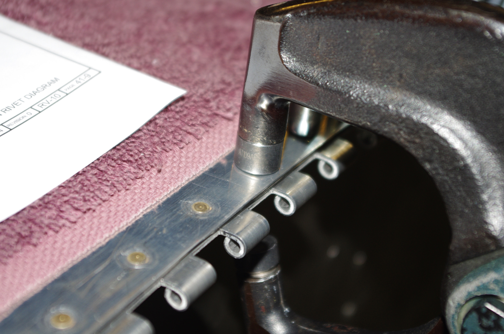 Next were the cowl attach hinges. These were prepared earlier, now just held in place with clecoes and spring clamps. The alligator jaw, dual piston pneumatic squeezer was perfect for rivet installation.

 Cowl hinge results shown from top and bottom turned out very well.

 The technique used to rivet the side seams was different from previous work on the fuselage. In this case a large, heavy bucking bar was held on the outside and the shop heads were back driven from the inside. This approach helped smooth the seams, plus reduced the shallow skin cupping seen on earlier efforts.
 The upper forward fuselage interior is now ready for installation of the instrument panel. However, there are some further fuselage activities to be performed prior to then.