I have not posted recently due to business travel and other real life issues getting in the way. In addition, I have reached the stage where planning for electrical runs, bulkhead penetrations, antenna locations, battery selection, etc. are all necessary to finalize decisions before cutting or modifying any standard parts is required. Much time has been spent learning how to use a freeware CAD package called DraftSight and reading the AeroElectric Connection book on plane electrical systems. Initial design sketches have been prepared, but much more thought is needed.
In the meantime backing plates for antennas and the NACA air inlets can be prepared in parallel while the electrical design continues.
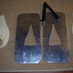
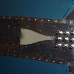
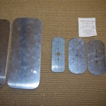 First up was preparing a prototype of the transponder and ADSB antenna backing plates from scrap material (center). Rough outlines were then cut at the same time for the antenna plates, plus backers for the NACA vents to be installed in the tailcone side skins. The outer edges were then sanded smooth and polished on the Scotchbrite wheel.
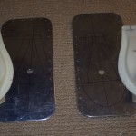
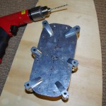 Outlines for the antenna holes and supporting rivets were measured, then match drilled between two plates – one for transponder and the other for ADSB. The dimensions are not exact, as the backing plates will not be visible outside the plane.
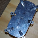
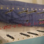
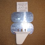 Here are the final antenna plates ready for installation. I will drill the rivet holes in the skins first, then clecoe the plates before drilling out the final antenna holes with a unibit. My plan is prepare the plates for all antennas, finally decide on location, then install about the same time the wiring harness design is finished.
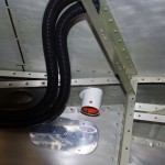 Here is one possible location of the ADSB antenna – forward of the baggage door on the left side and near the step hardware. This location will require an inspection port anyway for the step bolt examination, cable chases for power lines, and the antenna attachment. Being on the left edge also allows the required 3 foot separation from other transmitting antennas. My current thought is place the transponder antenna exactly on the opposite side with a similar inspection port. This gives the needed separation as well.
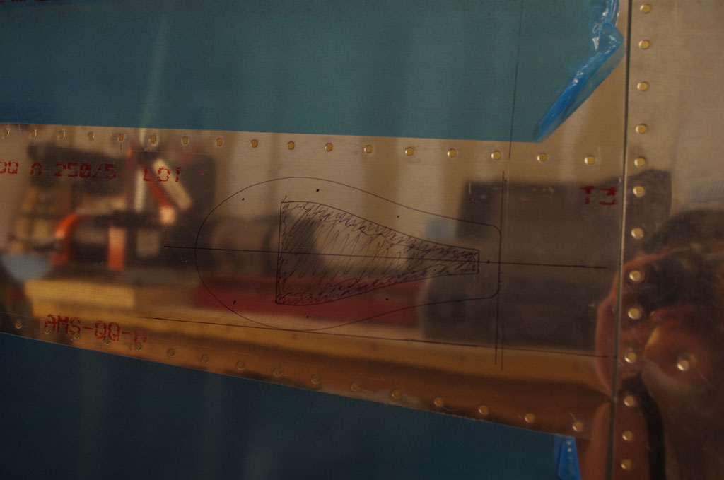
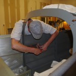
 Next up is preparation for cutting the NACA vent opening in the side skins. The second bay up and between stiffeners has been marked for processing.
 Two holes from the inside, then clecoe the backing piece on the outside to finish match drilling the outer plate rivets.
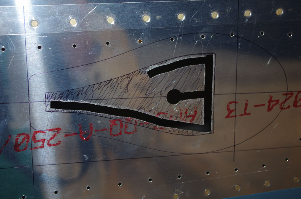
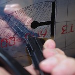
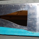
 Here the backer is clecoed in position on the inside. Next steps are drill a 9/16″ hole as the initial entrance for a hand-held nibbler. The inner vent material cross-hatched in black will then be removed prior to using ProSeal to attach the vent itself. Many internet posts suggest using ProSeal alone is sufficient to hold vent in place. I will be using that approach and will only apply screws as a last resort. We shall see how this holds up.
 The pilot hole is drilled into the skin, just big enough to fit through the nibbler head.
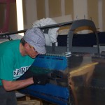
 My first use of a nibbler. Each bit takes about a 1/16″ x 1/4″ piece from the skin. I just went slowly around the edge to rough in the shape.
 Rough nibble underway, complete, then initial rough hand filing on the skin only.
 The same process was used on the backing plate, just not attached to the plane.
 After roughing out skin and plate, then the combination back on the plane is filed and edges smoothed with Scotchbrite.
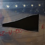
 The smoothing is complete on the right outside, and a corresponding view from the right inside.
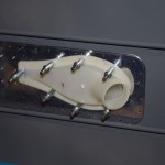 Here are the same views for right outside/inside, this time with the plastic vent scoop clecoed into place.
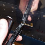
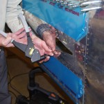 The last steps for now are dimpling the back plate rivet holes. Here a pop riveter is used with low clearance dimple dies to prepare for 3/32″ rivets. Next on the list will be alodine and prime the backing plate, then ProSeal for final attachment. In retrospect the backing plate is probably overkill and could be reduced in size. I will probably use a smaller format on the forward scoops (skin already prepped from the Quickbuild kit).
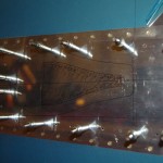
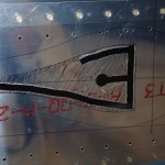
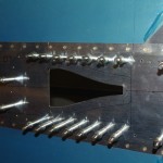
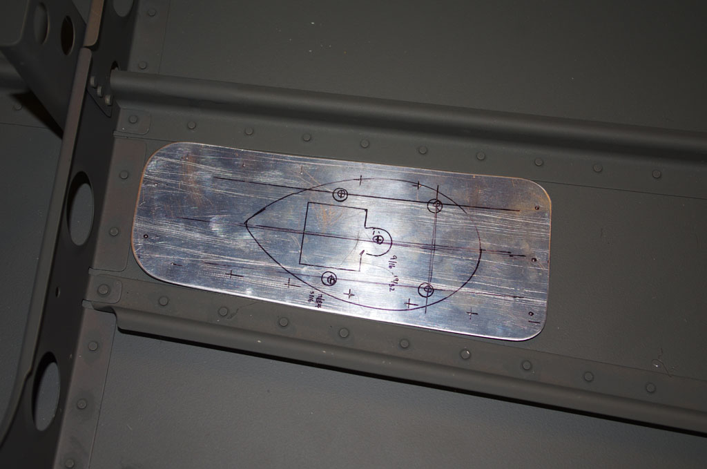 The layout of the antenna fits just right between two stiffeners near the center part of the tailcone. Here the rough plate is marked for initial drilling.
 The initial drill of three holes was done inside the plane. Then the plate was moved to the outside to match drill first the holes for the antenna mount, finally the plate holding rivets.
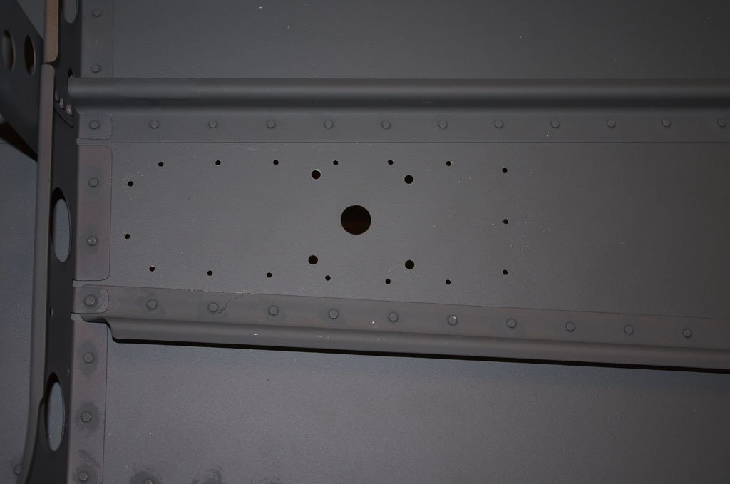 Here the final hole pattern for the antenna mount.
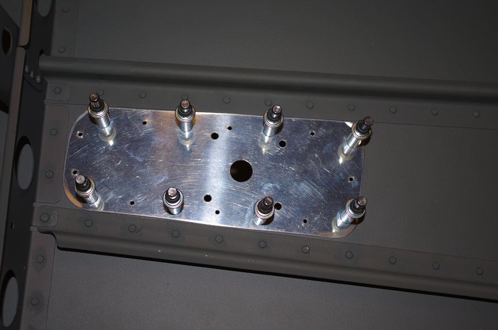 Here’s how the plate looks clecoed back into position on the inside.
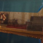
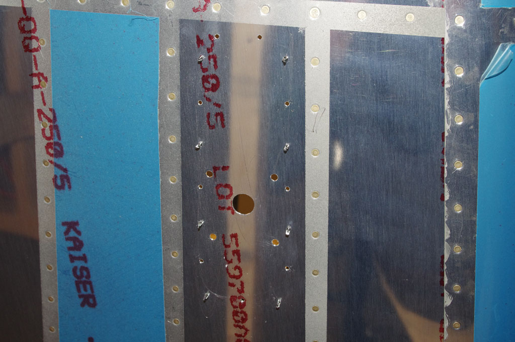 And finally … a view of the antenna mounting location from outside. As with the other plates, alodine and prime treatment will occur before final attachment.