Category Archives: Section 48, Gear Leg And Wheel Fairings

Engine, Propeller and Final Preparations

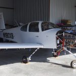
The final installations have begun after many years of component fabrication.
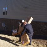
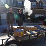
My son and I carried the propeller out of basement storage for transport to the airport.
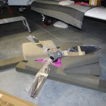


The unwrapped propeller on the floor was checked, then hung by Terry, Eric and I.  Sorry no photos were taken during that process.  Needless to say, everything went well and the prop looks great.  Easily the best looking thing about the aircraft!
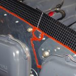


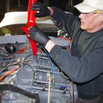
High temperature RTV was applied to gaps in the baffling and between cylinder heads.  The engine was then filled with 12qts of Aeroshell 100 mineral oil, which will be used for the 25-30hour engine break-in period.
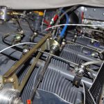
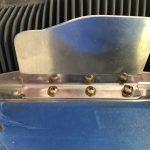


Final connections of the propeller governor cable and bracket adjustments were made. The air dams with their original heights were installed.  These were later reduced in size after some initial flight tests were performed.
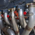


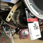
EGT probes were installed in the exhaust manifold, then bundled with their corresponding CHT probe wires. The alternator belt was tensioned and Safe-T-Wired secure.
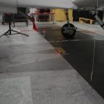
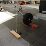


Measuring the leading edge of the wing provided a reference point for the CG calculations.
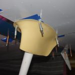


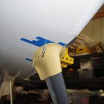
Intersection fairings for the gear legs were initially fit, then later painted and installed after the TS Flightlines stainless braided brake lines.
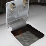
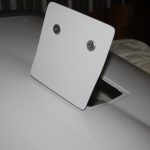


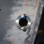
Final installation of the oil door with hidden hinge…
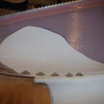


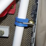
A 1/16″ ceramic mat was contact cemented in the lower cowl, then covered with Vans aluminum heat shielding.  This combination should prevent the cowl paint from being scorched by the exhaust manifold heat.  Lower cowl pins will be secured against these Adel clamps with tie wraps.
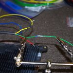


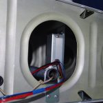
Final wiring for AeroLED VX landing lights were Solder Sealed, then run through conduit to the wingtips.
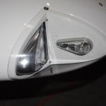
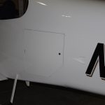


AeroLED VX landing and NS position lights/strobes…
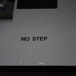


Decals applied to flaps and doors…


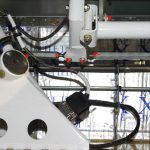
Wiring from control sticks to system buses used DB15 connections for easy maintenance or removal.
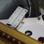
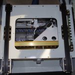


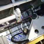
Ground wires were covered in thick rubber fuel lines to prevent chaffing, then seat pans were installed.
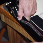
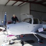


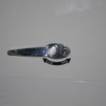
Aerosport auxiliary seat handles were installed for easier operation. Then final inspection and review of everything to date.


All that’s left before first engine start is sit back and wait for good weather outside. It certainly has been a long time coming.  Very excited about this next major milestone.
Gear Leg and Wheel Fairings (2)

The last few months have been focused on completing any prime/paint activities, as the paint booth facilities will not be available to me after October 31

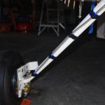
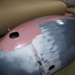
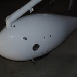
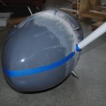
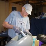
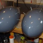
The front wheel fairing needed some AwlGrip filler to even the transition from fore to aft section. The final painted assembly looks very good.


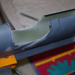
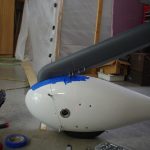
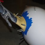
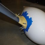
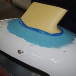
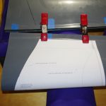
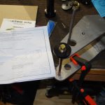
The right photo shows the initial shaping of the leg fairing. A construction laser was then used to locate the nutplate holes through the fiberglass web for accurate drilling.


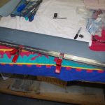
Then .063 Piano Hinge was attached and a pin fabricated to length.  The final configuration is shown on the right.  Subsequent steps related to smoothing the rivet lines (namely resin fill, followed by SuperFil, Smooth Prime, spot putty, prime and then paint.)


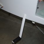
The steps were powdered coated and painted in previous posts.  Here the tread portion was treated with UltraWing Walk anti-slip compound.  This material contains heavy duty grit particles and cured to a rock hard surface.  This will provide an excellent surface on the installed steps for getting into the airplane.


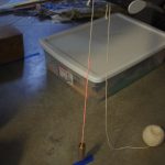
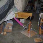
The steps then served as a reference point for leveling the fuselage and horizontal alignment with the ground to set the appropriate angle on the main gear fairings.  Again construction lasers were used for accuracy.  The left photo aligns the step reference parallel to the fuselage centerline, while the right ensure vertical alignment to a plumb bob hung from the step.


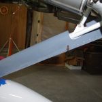
With references now vertical and horizontally aligned with the fuselage, the fairing back-sweep angle was set to direct point backwards to the step reference point.  This should ensure minimized wind resistance during flight.


After setting the proper sweep angle on the leg pieces, the intersection fairings were drilled to the same orientation. Eventually these parts will be secured with nutplates and will constrain the leg fairly in the correct configuration.


Here were two views of the final setups.


After completing the fairing alignments, I decided to complete blending the intersections to the wheel fairings. I had originally thought to do this after the flight testing phase, but moved forward with the repainting due to the paint booth access limitations.

Gear Leg and Wheel Fairings (1)

Aligning and fitting the wheel pants required use of two lasers, one for the aircraft centerline and one for accurately locating the pant retention bracket holes.

The fuselage had to be leveled, then raised so wheel installation would leave the wheels just touching the ground. Here the wheel dollies from Charlie Derk (with many thanks) were removed for actual wheel installation.


The main wheels and brake fixtures were bolted into place. Again the plane was leveled and wheels just barely touching the ground.


A .75″ x 1.0″ spacer block established the upper position of the main wheel pant. With the forward and aft sections clecoed together, alignment to aircraft center and level reference datum could proceed.


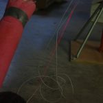
A regular construction laser provided an accurate centerline for the airplace. Measuring offsets to this reference line and the front/aft of each wheel pant ensured parallel alignment. The pants were also measured from the floor to their own centerlines to make sure they were parallel with the ground.


A second construction laser provided accurate location of the holes drilled in the retention brackets. The same processes described above were used with both main pants and the forward wheel pant.


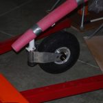
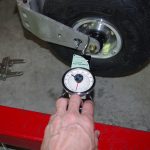
The forward wheel was first installed, then the side breakout pull of ~25lbs was measured with a baggage scale. The Nose Fork Assembly nut was tightened to approximately achieve this value.  I have heard from other builders that this nut will need adjustment many times during the fly-in period.


All wheel pants drilled and temporarily clecoed in position in the left photo.  Forward wheel pant protectors were then aligned and holes drilled to prevent two bar damage.


Finally for this section, the pant retention brackets were surrounded with resin/silica to provide larger bearing surfaces during normal flight operations between the fiberglass and the brackets.  Additional resin will be applied in a later post to round over and slightly enlarge the bearing points.


MISCELLANEOUS

The door windows were retaped prior to the next batch of final paint.


The inital painting of the horizontal stabilizer left a few runs and some flaking along the trailing edge of the upper side.  Resanding and air brush priming were performed before another (hopefully final) paint coat was applied.


The #2 cylinder fuel injector line required two adel clamp locations to secure between the prop governor cable bracket.

Wheel Fairings (1)

Progress has been made over the summer in my air conditioned basement workshop, I have just not kept up with routine posts.  A series of updates for actions taken over the last few months should be appearing soon.

The next items after working on the wheels, axles and brakes are the initial rough assembly of the wheel pants.

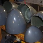
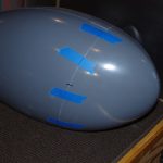
The shell halves of fiberglass need to be fit together.  As has been the case with all fiberglass parts so far, tolerances from one part to another are just approximations.  Much hand sanding and fitting is needed to align the edges properly.


Once the main shells are close, finding the exact vertical and horizontal alignments of the main sections is needed. The Vans plans describe how to determine this geometry on the parts.


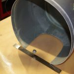
Enlarging the default openings to greater than called for in the plans seems to be required for good operational results.  Friends with RV10s have described wheel pant rubbing, or even fractures in the pant structure as the result of tire expansion contact with the pant on landing.


The strut fairings have fairly complicated shape due to hanging back and out from the fuselage. Fortunately a template is provided in the plans.

Landing Gear (1)

I will be using Matco brakes and wheels for this build.  The design and quality of their parts is excellent.  Friends with similar installations on their aircraft highly recommend the braking capacity as compared to the stock items available from Van’s.  Also the front axle is replace with a version which cannot rotate, instead forcing the wheel to spin on the bearings (as intended). Apparently the original designed axle can spin along with the wheel itself.  This causes wear and eventually serious vibration over time.

FRONT WHEEL

On the left are the available parts for the front wheel laid out for inspection.  Side standoff blocks where the front tow bar is attached must be fabricated from 1.5″ x 1.25″ x 0.75″ pieces of aluminum.


To prevent the Matco axle from rotating with the wheel, a retention bolt must be inserted through the front fork.  The receiving piece is fastened on the outside to act as a drill guide for the drill/ream operation shown on the right.


Outcome of the drilling operation – perfect fit.


Once the tube and Aero Classic 5.00-5, 6 ply tire retread from Desser are mountedd on the hub, static balancing is performed. For this wheel, the heaviest part always occurs where the valve stem is located.  A few motorcycle weights will need to be attached to the rim to compensate.


MAIN LANDING GEAR

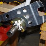
The left photo shows the main gear parts laid out for inspection.  The right picture is the wheel axle held by a custom wooden jig.  The horizontal  attitude of the hardened axle should make the wheel assembly easy


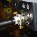
Standoffs and spacers between the brake torque plate and the wheel pant bracket are needed for correct alignment.  Here the spacers made from 3/8″ aluminum tube are measured with a digital micrometer to roughly 21/32 inches in length. They were subsequently rough cut on the bandsaw, then sanded to final tolerance on a 5″ tabletop sander.  The completed lengths across all 6 parts are very consistant.


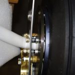
The spacers are visible on the left between the torque plate and the wheel pant bracket.  This space holds the brake caliper unit.


The assembled wheel fits just right. Note the black anodized Matco nut holding a spacer washer from the open bearing seal.  The nut is tightened just enough to keep the seal/race from rotating with the wheel – this job is for the bearings themselves.  A final step still to be completed is mark the correct position of the nut on the axle, then use a carbide end mill to create a hole for a retention cotter pin.


Here are different views of the mock assembled wheel.  Next is disassemble everything again, drill the cotter pin hole, torque the hub bolts, and prime the wheel pant bracket. The final assembly  will occur when the main gears are attached to the fuselage.