Aligning and fitting the wheel pants required use of two lasers, one for the aircraft centerline and one for accurately locating the pant retention bracket holes.

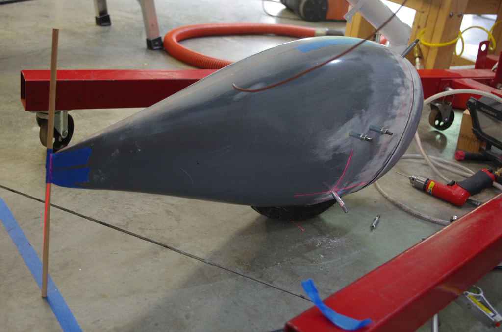
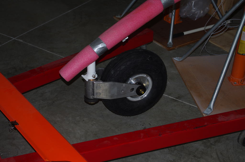
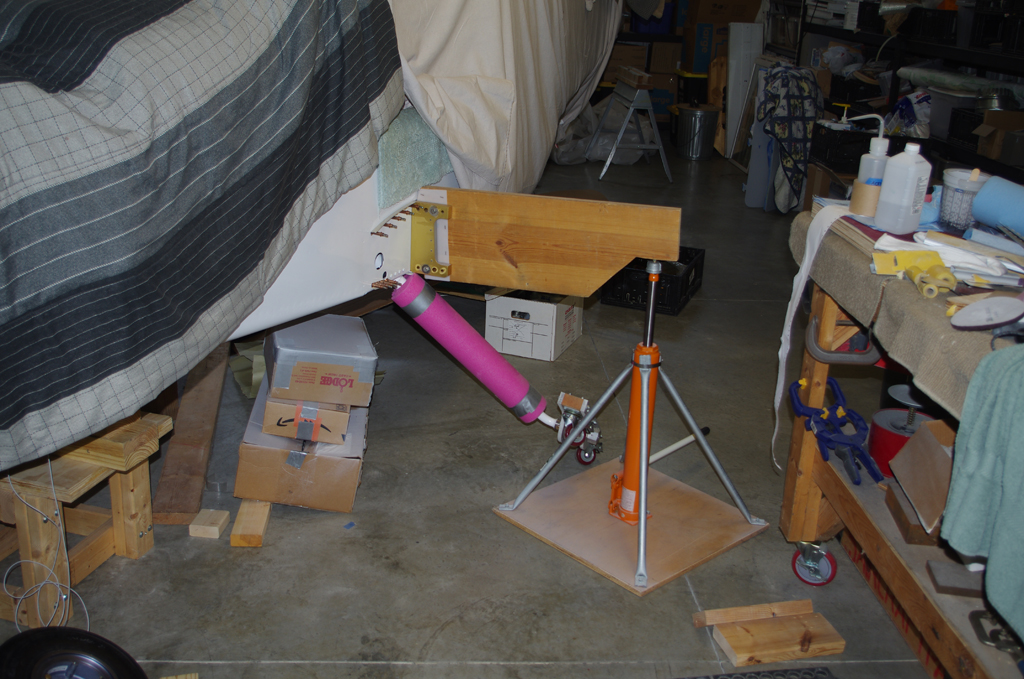 The fuselage had to be leveled, then raised so wheel installation would leave the wheels just touching the ground. Here the wheel dollies from Charlie Derk (with many thanks) were removed for actual wheel installation.
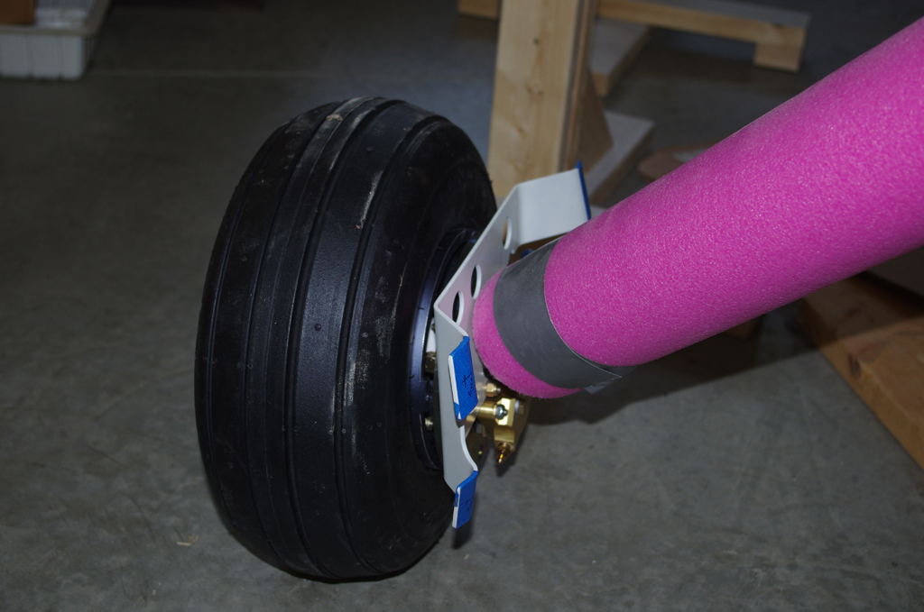
 The main wheels and brake fixtures were bolted into place. Again the plane was leveled and wheels just barely touching the ground.

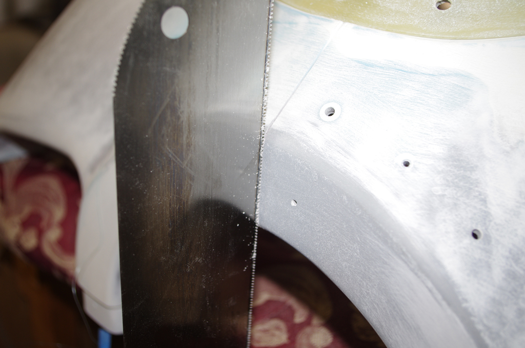
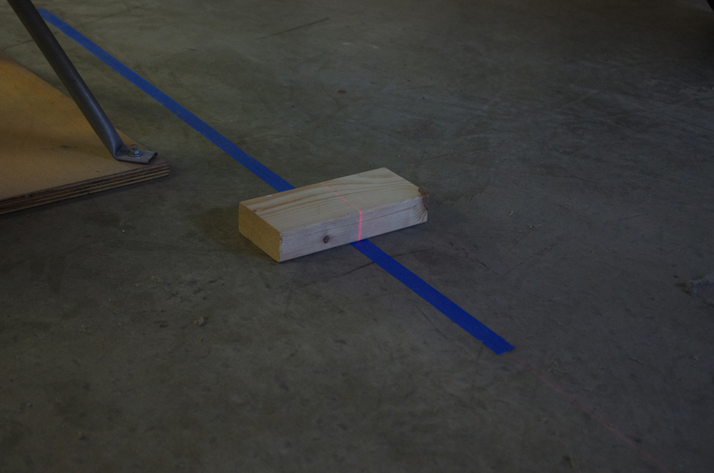
 A .75″ x 1.0″ spacer block established the upper position of the main wheel pant. With the forward and aft sections clecoed together, alignment to aircraft center and level reference datum could proceed.
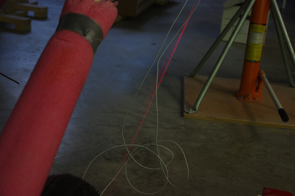
 A regular construction laser provided an accurate centerline for the airplace. Measuring offsets to this reference line and the front/aft of each wheel pant ensured parallel alignment. The pants were also measured from the floor to their own centerlines to make sure they were parallel with the ground.
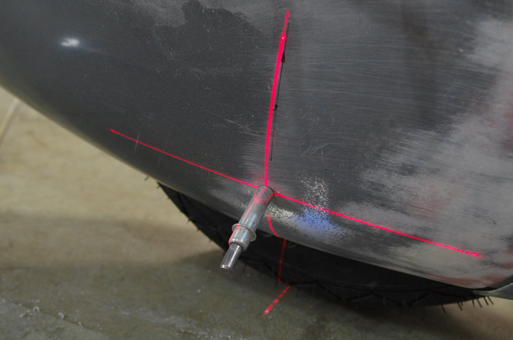
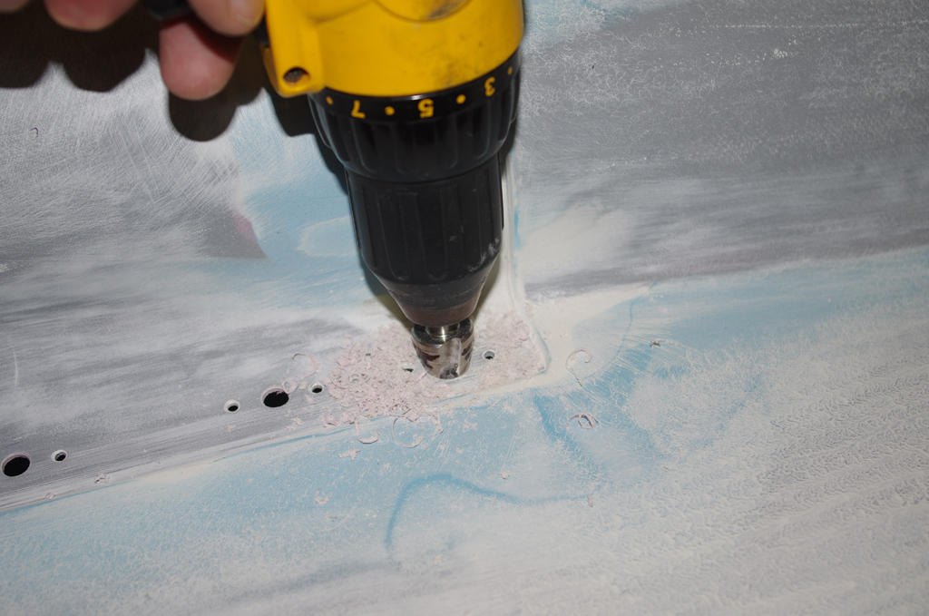
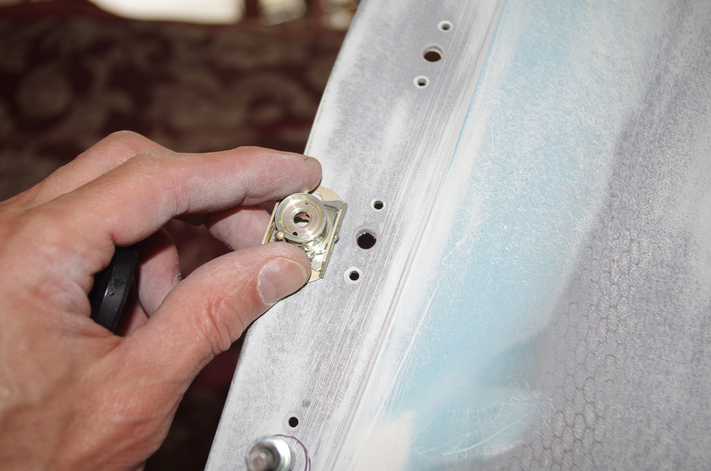
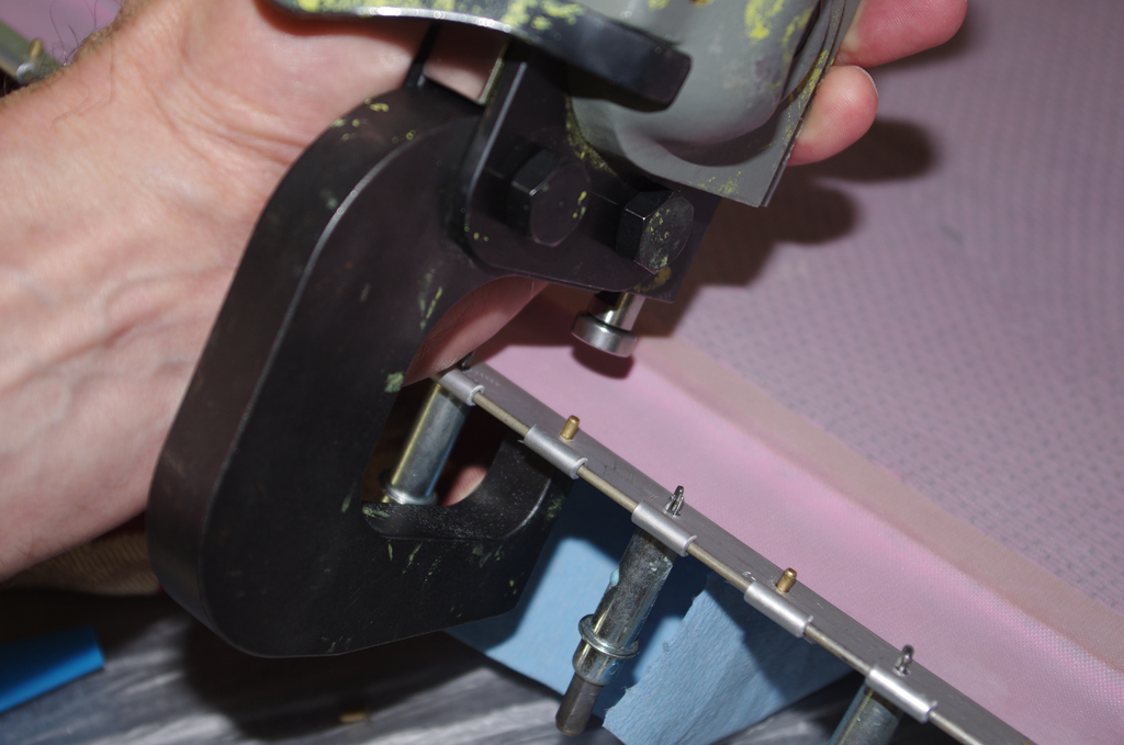
 A second construction laser provided accurate location of the holes drilled in the retention brackets. The same processes described above were used with both main pants and the forward wheel pant.
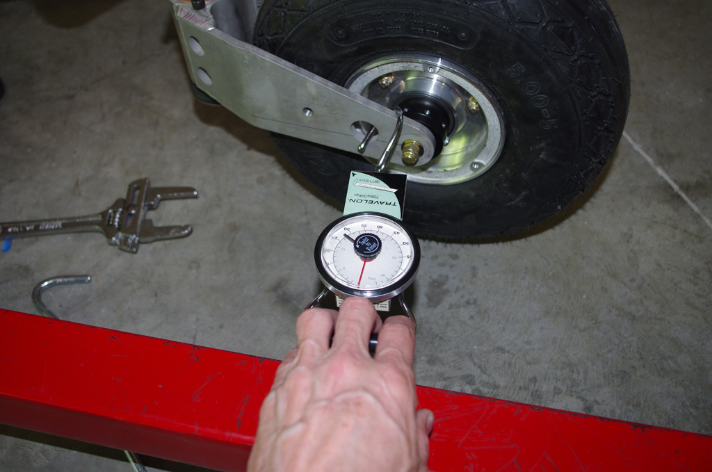
The forward wheel was first installed, then the side breakout pull of ~25lbs was measured with a baggage scale. The Nose Fork Assembly nut was tightened to approximately achieve this value. I have heard from other builders that this nut will need adjustment many times during the fly-in period.
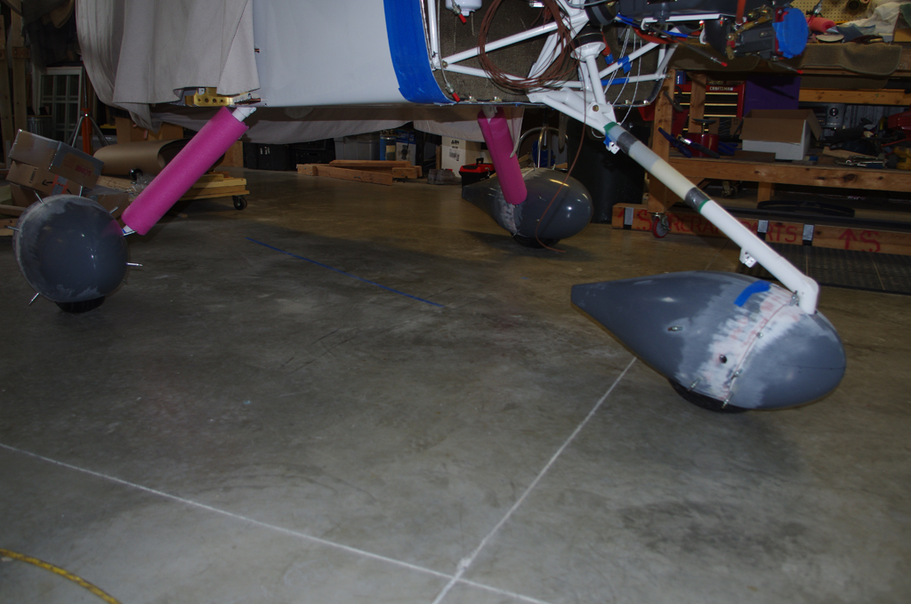
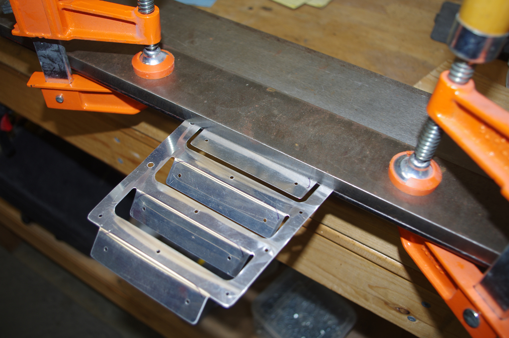
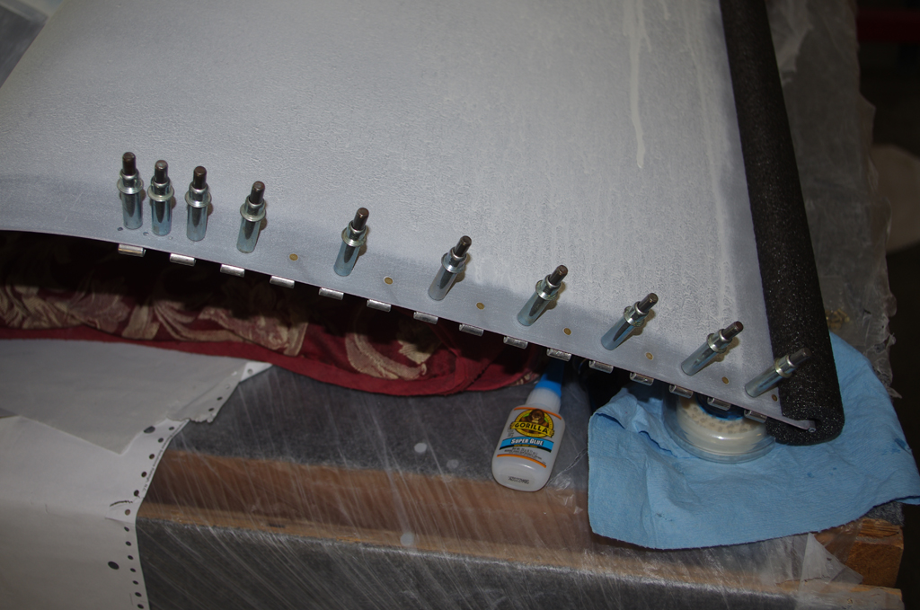
 All wheel pants drilled and temporarily clecoed in position in the left photo. Forward wheel pant protectors were then aligned and holes drilled to prevent two bar damage.
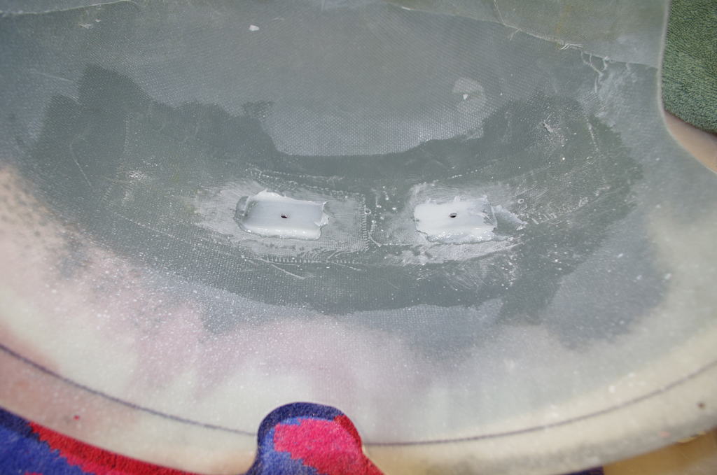

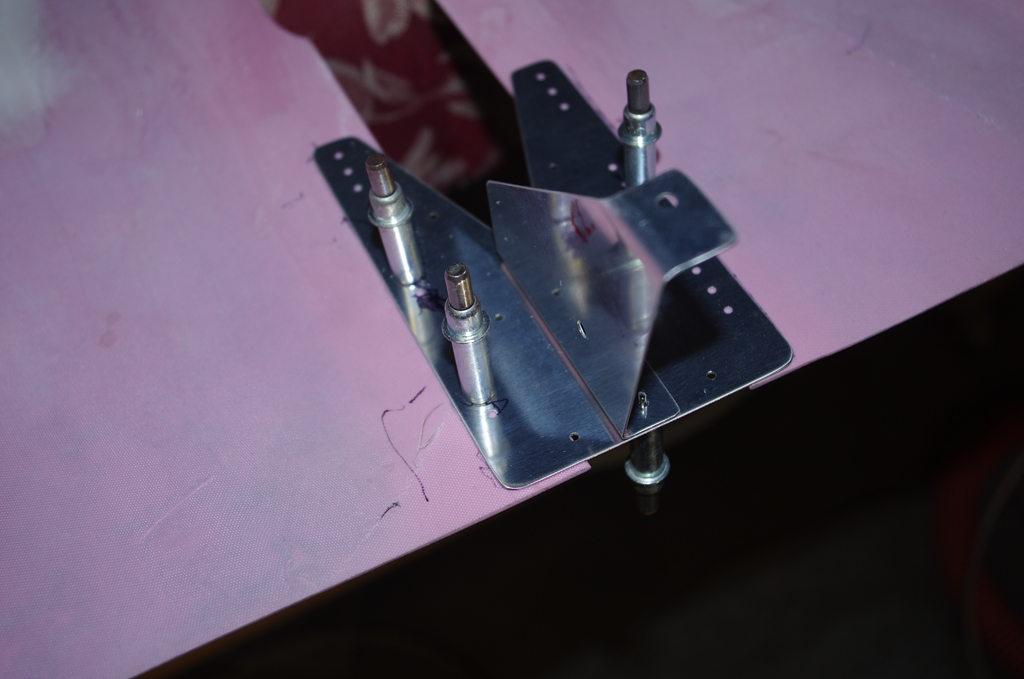
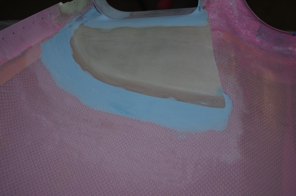
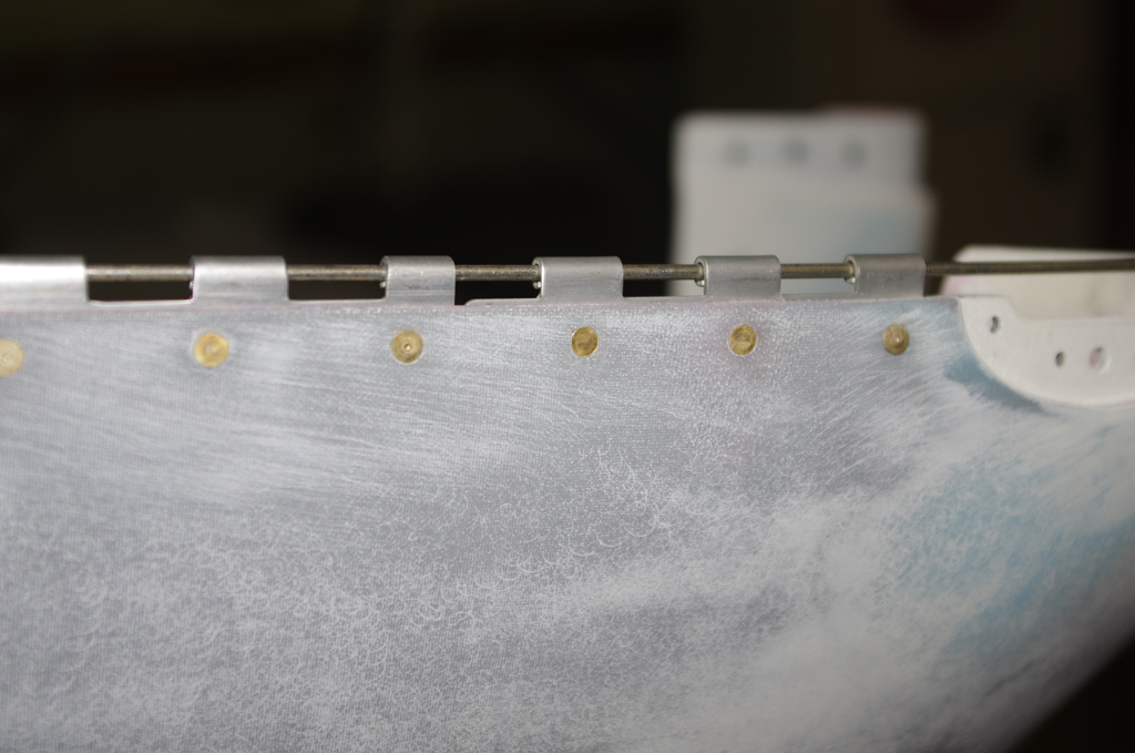
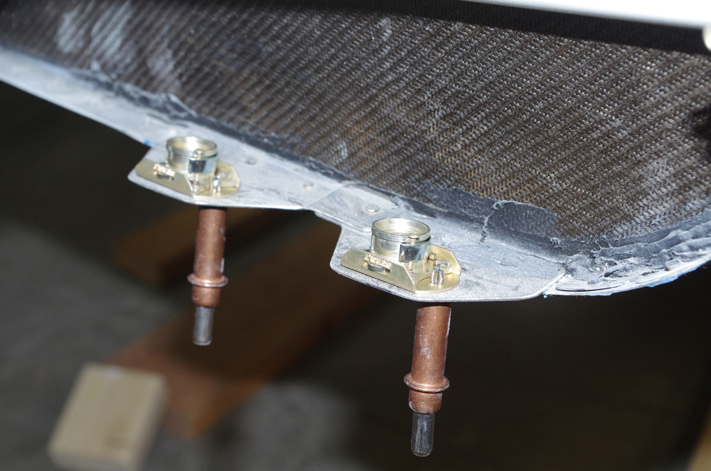
 Finally for this section, the pant retention brackets were surrounded with resin/silica to provide larger bearing surfaces during normal flight operations between the fiberglass and the brackets. Additional resin will be applied in a later post to round over and slightly enlarge the bearing points.
MISCELLANEOUS
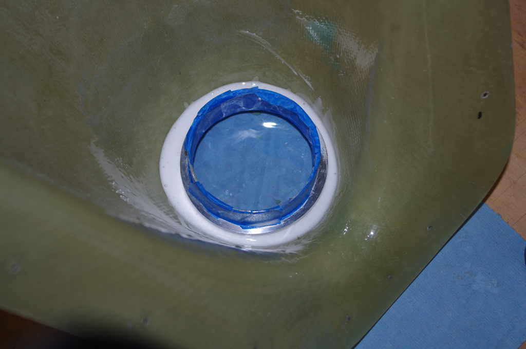
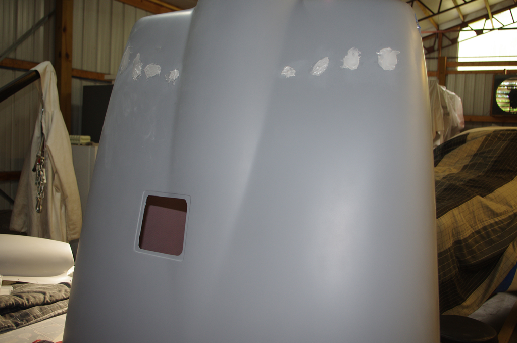
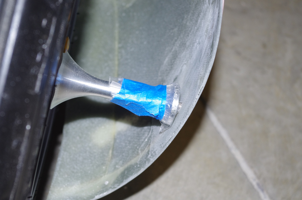
 The door windows were retaped prior to the next batch of final paint.
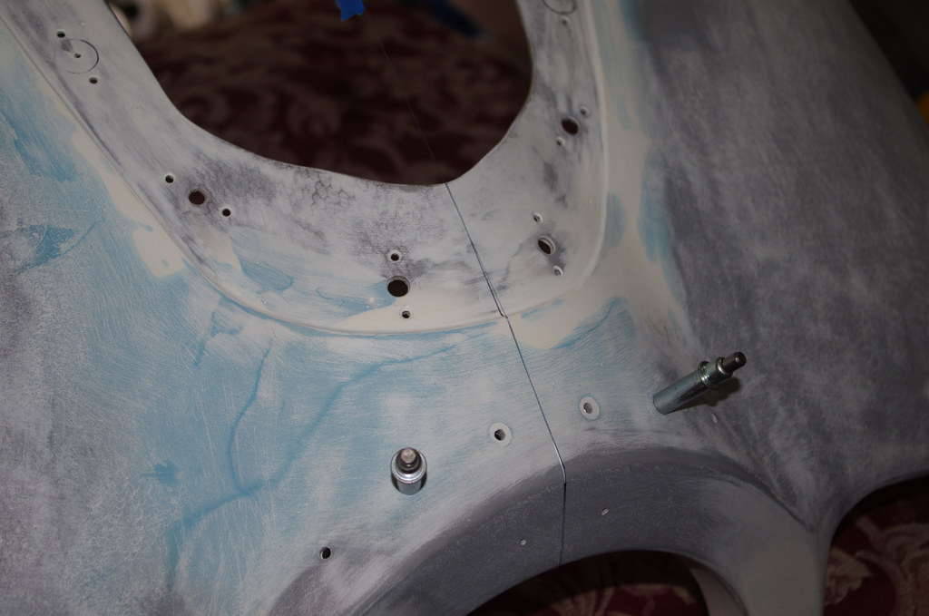
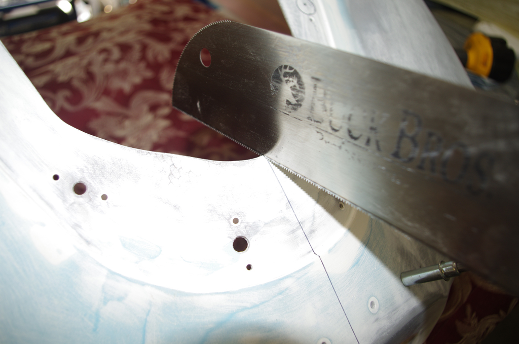
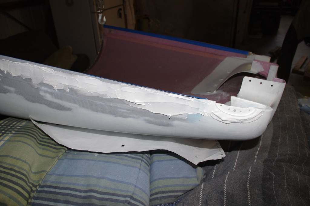
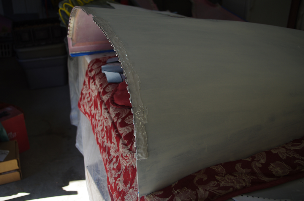
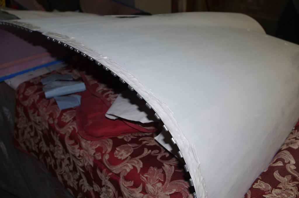
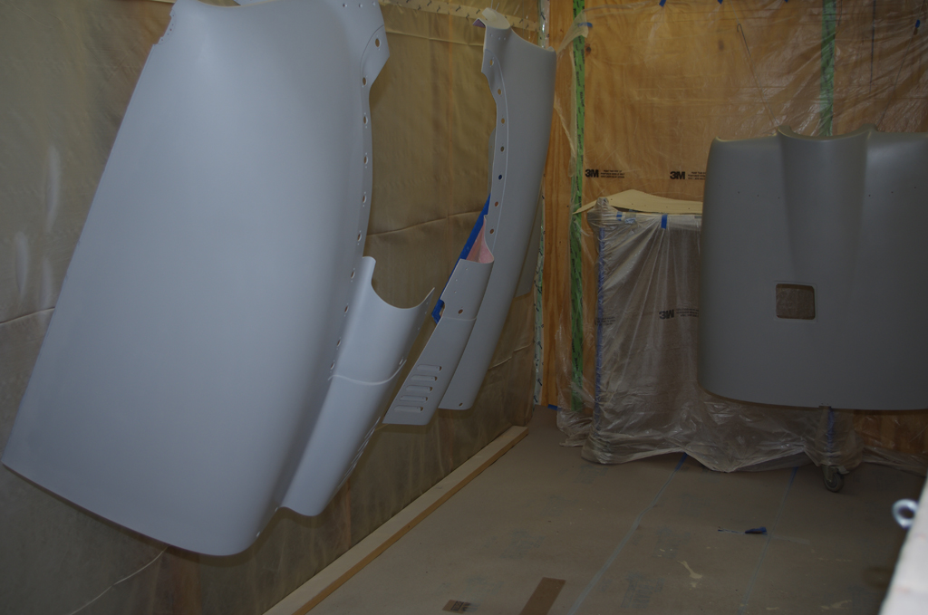
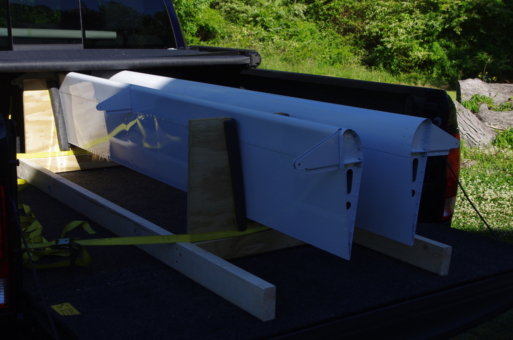
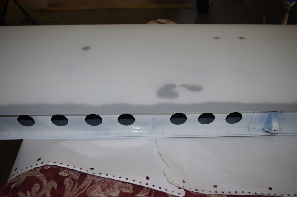 The inital painting of the horizontal stabilizer left a few runs and some flaking along the trailing edge of the upper side. Resanding and air brush priming were performed before another (hopefully final) paint coat was applied.
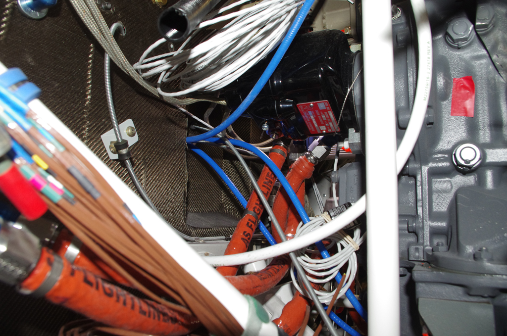
 The #2 cylinder fuel injector line required two adel clamp locations to secure between the prop governor cable bracket.