Due to an interference between the original brake lines and the forward tunnel cover, I decided to a redo would be appropriate.
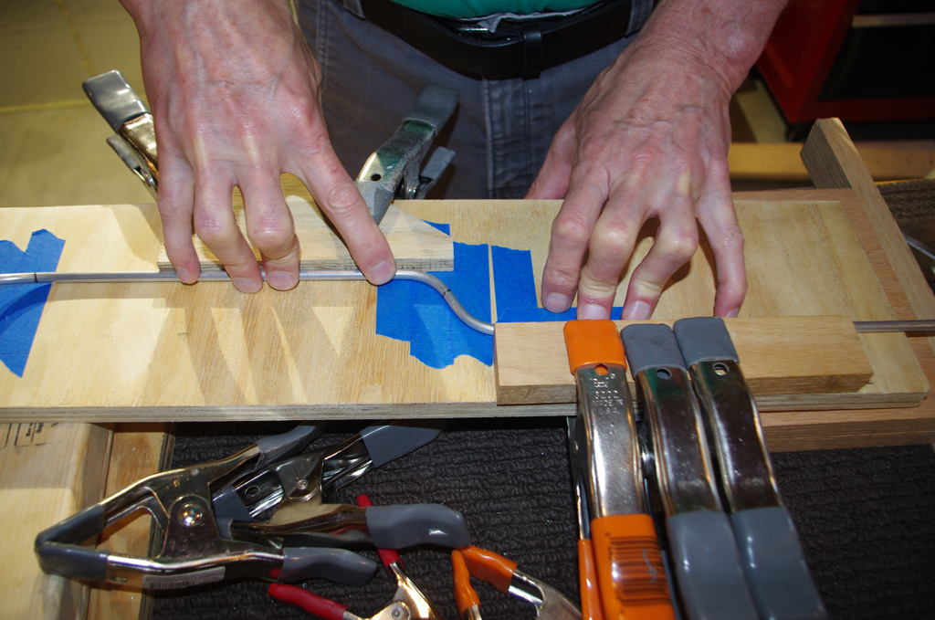
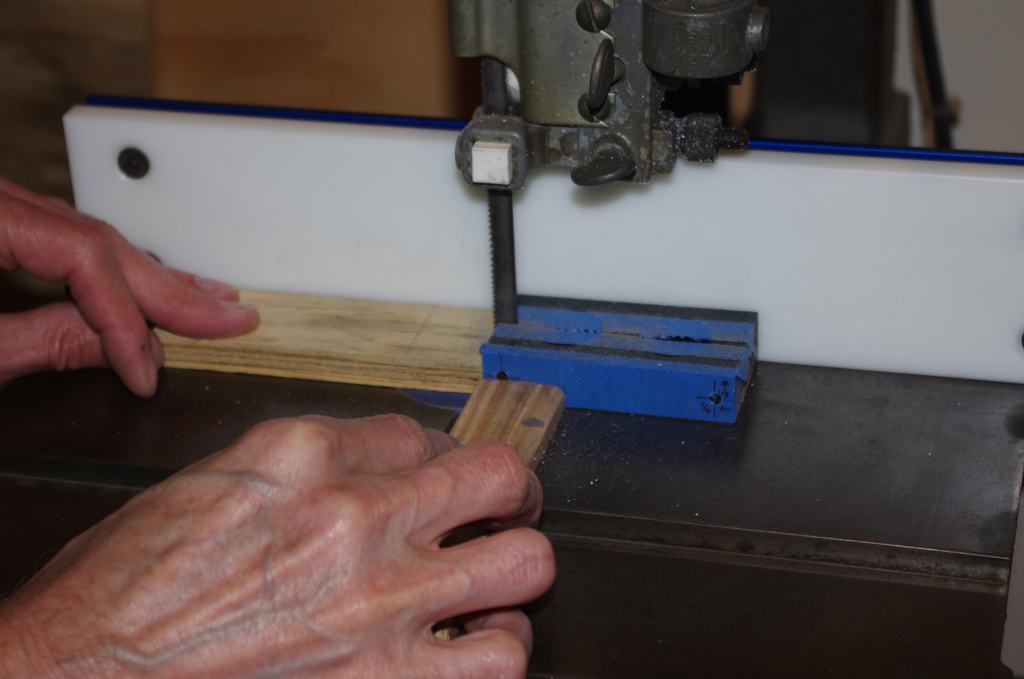
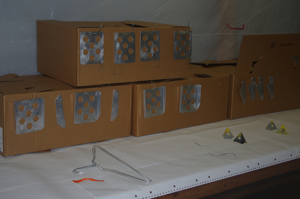
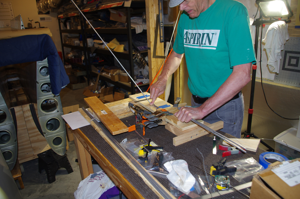 For this attempt at bending, a jig based on the exact firewall geometry was first emulated with coat hangers, then laid out on the workbench. The wooden constraints matched the indented box and helped make the two 45degrees bends in quick succession align properly.

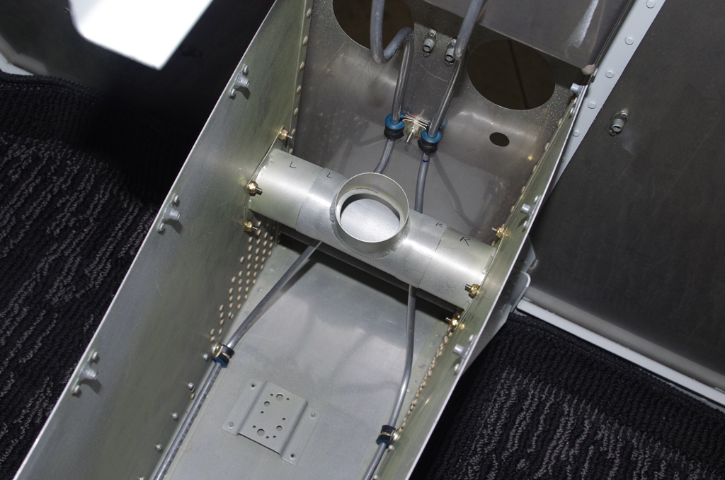
 The remaining bends were rough bent with the Imperial tube bending tool. The final configurations were carefully adjusted by hand. Since these were with the ‘hard’ aluminum, the risk of cracking or compressing during the manual operation was minimized. I am much happier with the final outcome.
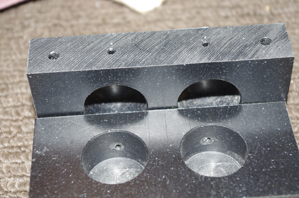
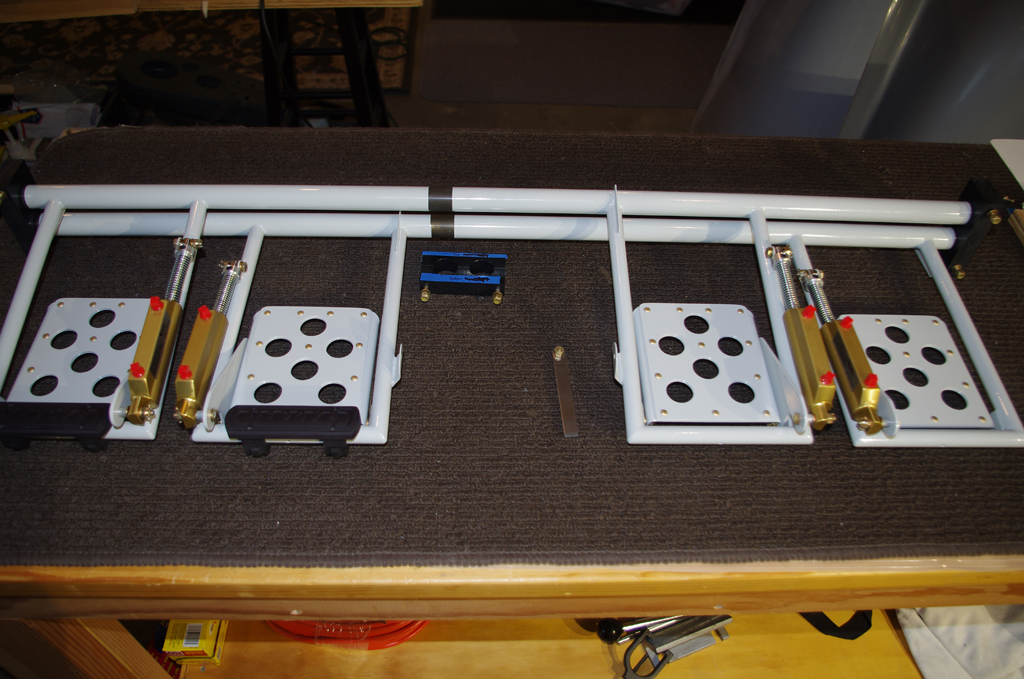
 Here the forward tunnel cover was relieved about 1/2″ from the stock cutout. Even the new, better fitting brake lines would not fit into the original space. On the right, the pilot side flexible lines were cable laced together on the workbench.

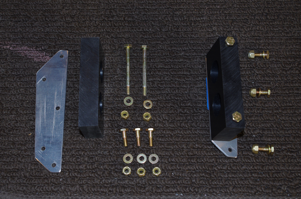
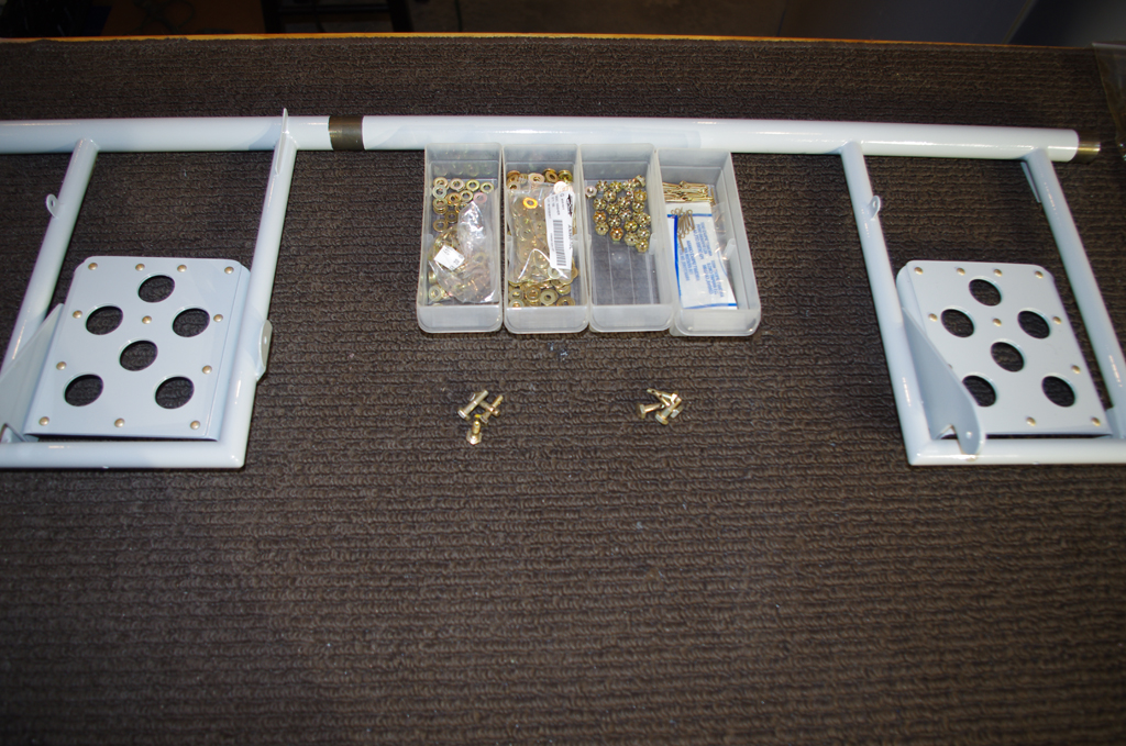
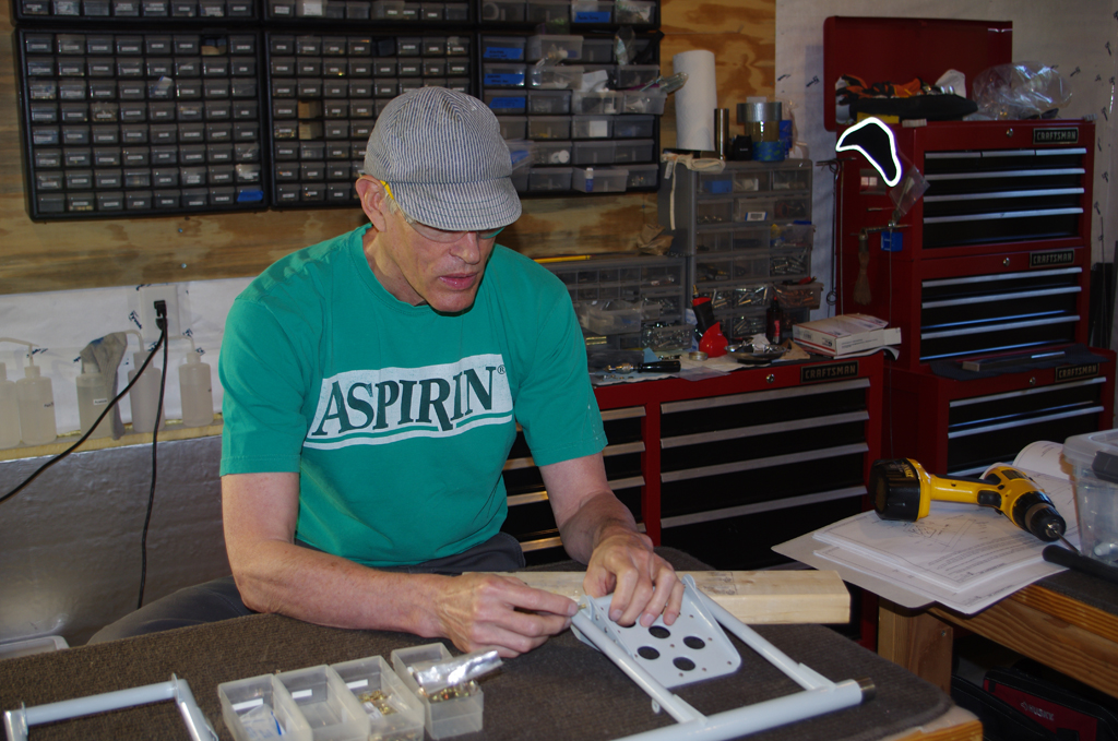
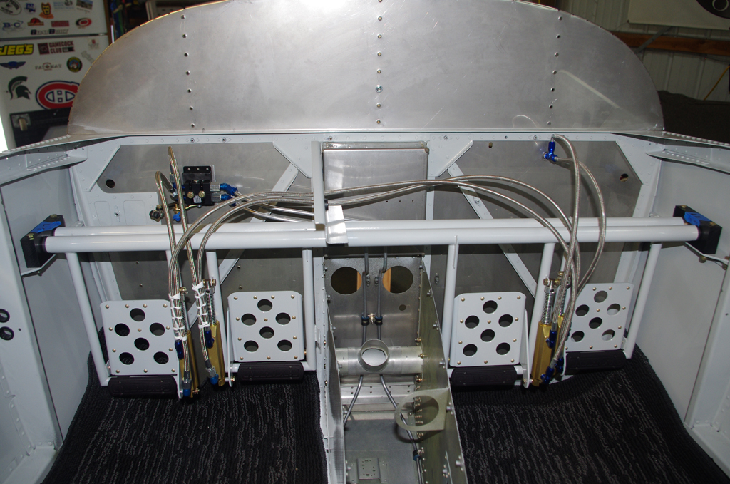 Here the rudder pedal / brake assembly is fit into the bearing blocks and bolted to the mount plates. The flexible lines were hand tightened to check for lines rubbing together. Pinch points will be covered with plastic spiral wrap, then final cable lacing where needed.
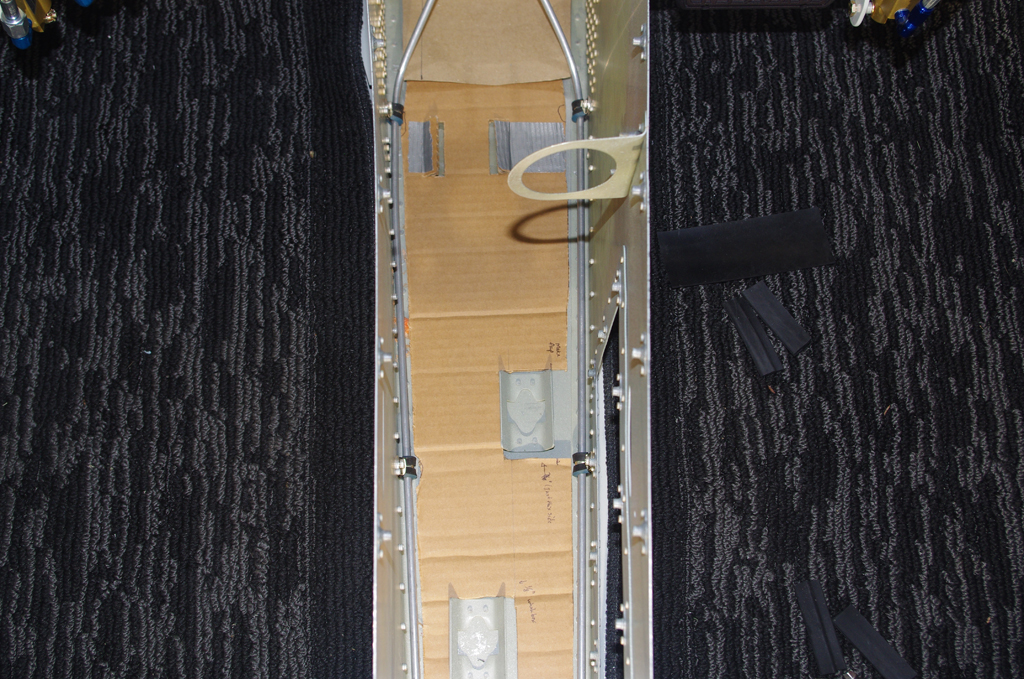
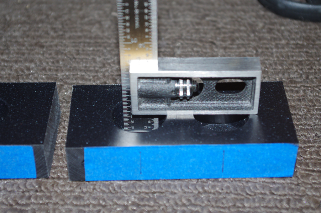
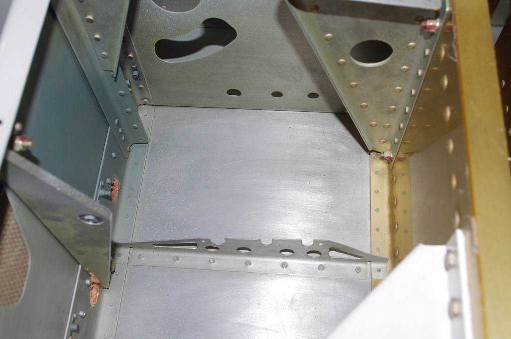
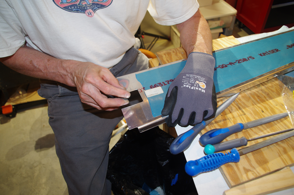
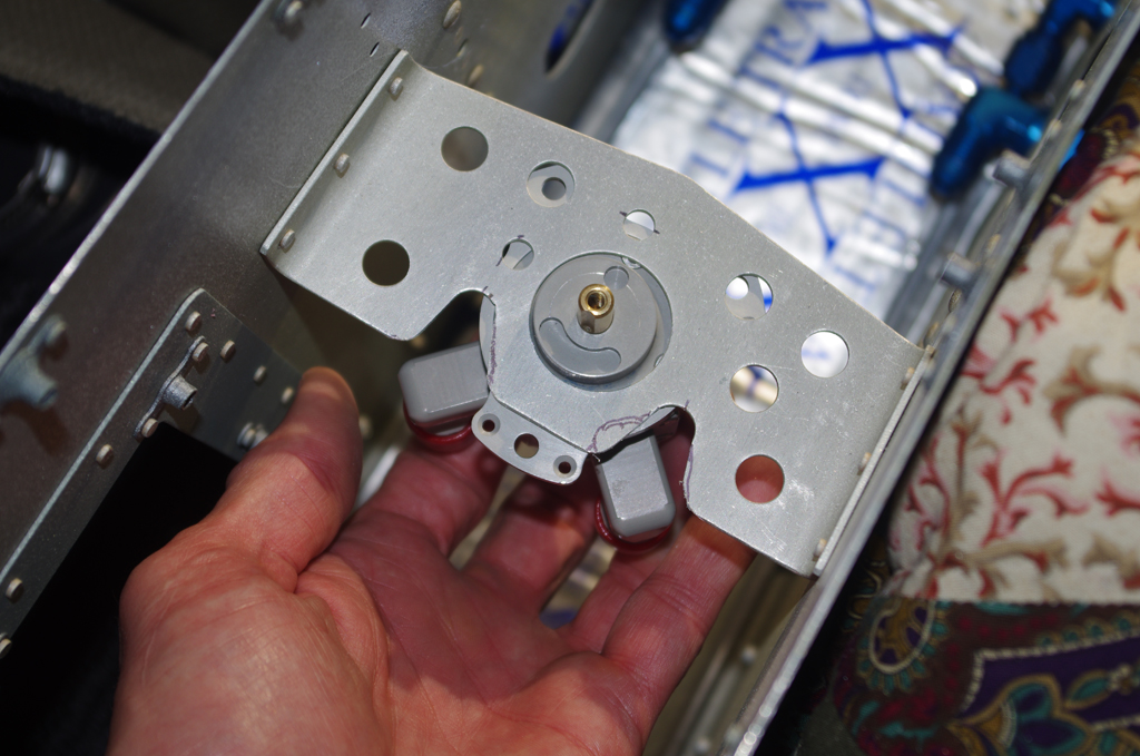 The left photo shows building a cardboard template for cutting ceramic mat insulation for the forward tunnel. RV10s generate plenty of heat transfer from this location as the engine exhaust pipes are immediately on the opposite side of the firewall. The right photo shows relieving the stock Vans fuel valve bracket to accommodate the Andair valve and TS Flightlines flexible fuel hoses. More on both these items later.