Preparation of the cowl baffling proceeded in parallel with the initial cowling work. I was essentially trying to optimize parallel work time utilization – while the resin dried on the cowls, progress was made on the baffles.
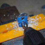
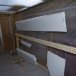
 Back riveting on the forward air dam material is shown on the left. Rough fitting the air dams is shown on the right.
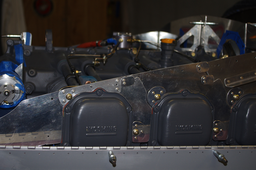
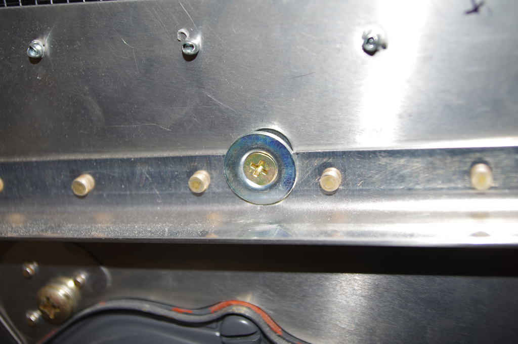
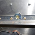
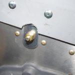
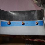
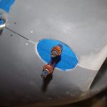
 The Vans plans call for fixed height, riveted deflectors in front of the #1 and #2 cylinders. Experience from other builders indicated these may need trimming to optimize airflow inside the upper cowl chamber. I elected to install #8 nutplates instead of rivets to allow easy removal of these parts for trimming or total replacement of these as needed.
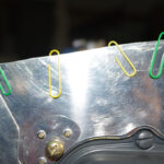
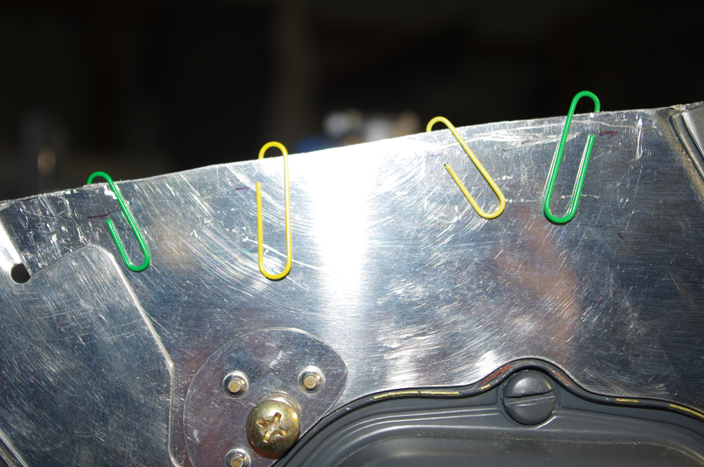
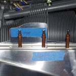
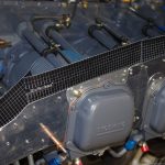
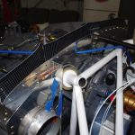
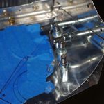
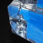
 Here the famous “paper clip method” was used to establish a 3/8″ gap between the solid air dam sides and the upper cowl surface. The trim lines are the final dimensions of the metal side plates.
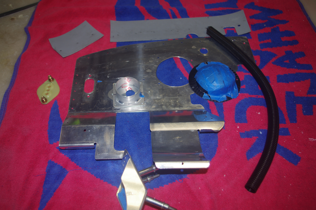
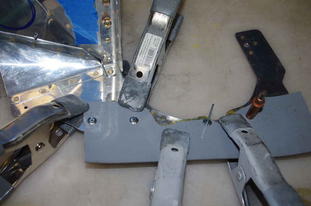
 Because the metal sides were so thin above the #1 and #3 cylinders, reinforcing backing plates were fabricated out of .032″ sheet aluminum to provide so additional strength.
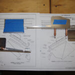
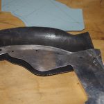
 The cylinder profile was created on construction paper to get a general outline. Then McFarlane air dam material was measured and cut. Pliobond adhesive was applied and spring clamps used to press for curing. This process did not produce great results, as the McFarlane material seems to have a siliconized coating to reduce friction against the inner cowl surface. Probably great for this purpose, but not helpful when attempting to bond with other materials.
 The inner side of the McFarlane dam material appears to be some form of rubber, while the outer side is smooth and laser etched to help conform bend to shape.
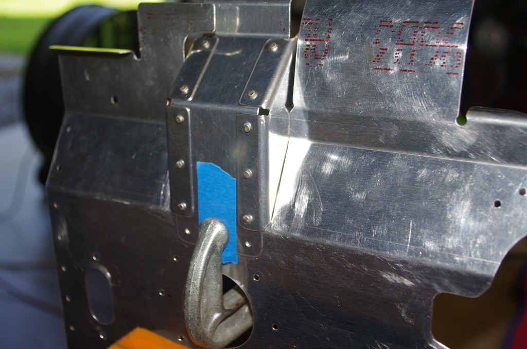
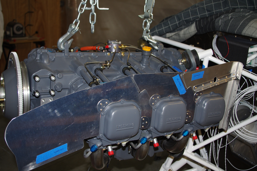
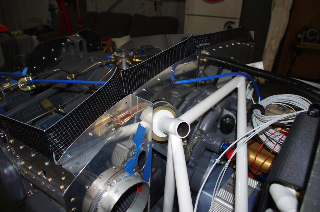
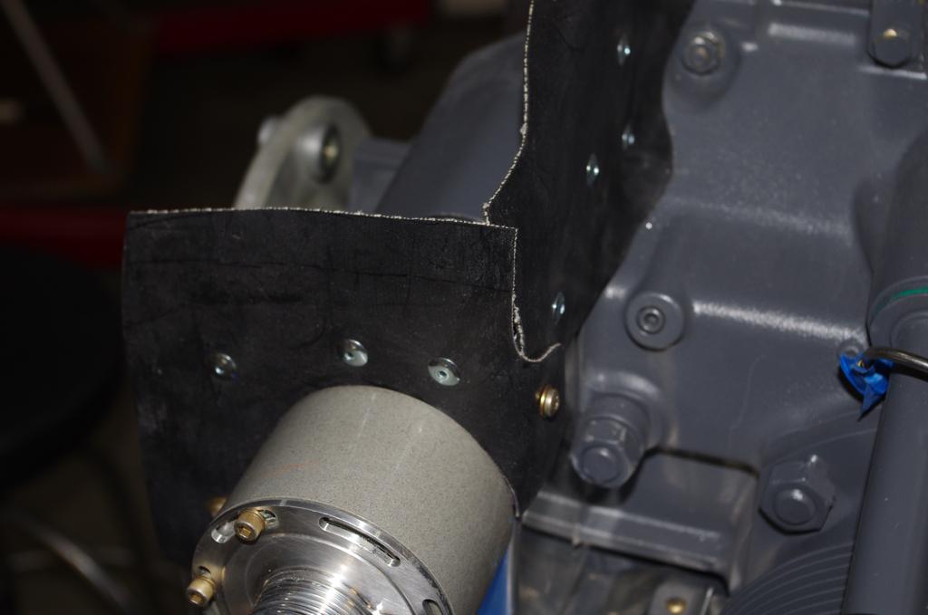
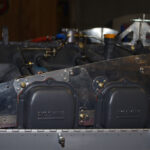
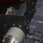
 The rear baffle panel was backriveted into place. Now that rivets have been applied, removing the combined pieces from around the motor mounts will be quite difficult. It was a tight fit beforhand getting the separate parts located around the cylinders and over the mounts.
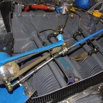
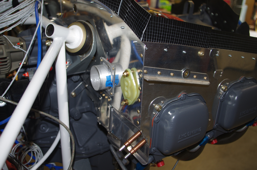
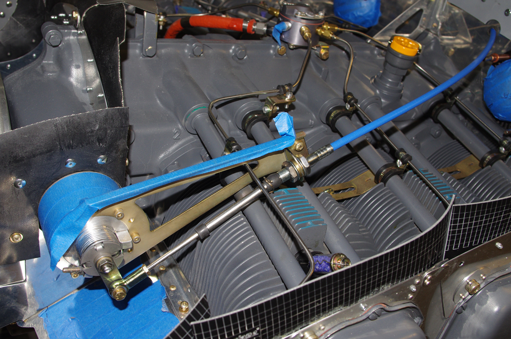
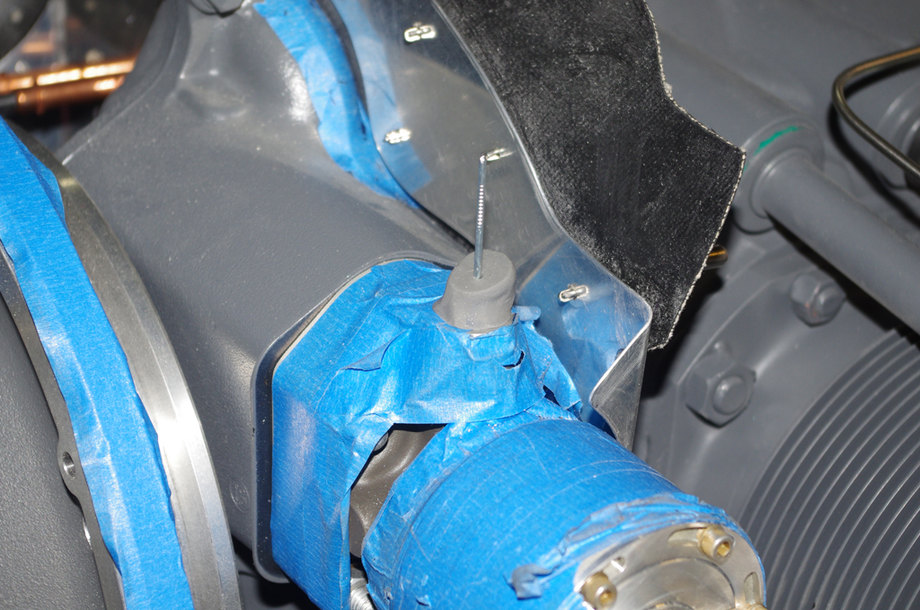
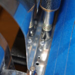
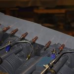
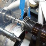
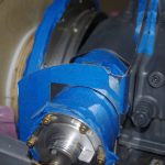
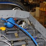 To finish the back baffle panel a hole for the propeller governor cable needed to be drilled. This required the final configuration of the cable mounting bracket to the prop governor. Notice how the #3 cylinder fuel injection line is configured to clear the bracket and cable.
 The side panels for #5 and #6 cylinders have access ports to allow socket wrench insertion for spark plug maintenance. These holes are covered during normal operations with removable components to prevent air loss during flight.
 Side gussets were custom formed for the front baffle plates, then riveted into place.
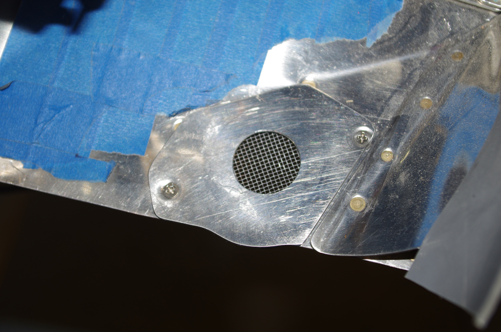
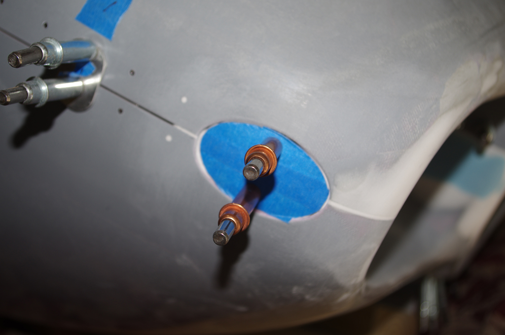
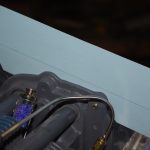
 The left front baffle was drilled and opened for one of the heater induction air ports.
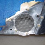
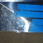
 The front heater induction port has a meshed screen installed, then rivet into place. At right, transitions between the upper and lower cowl faces were applied for a smooth surface.
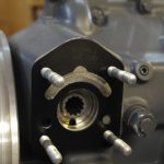
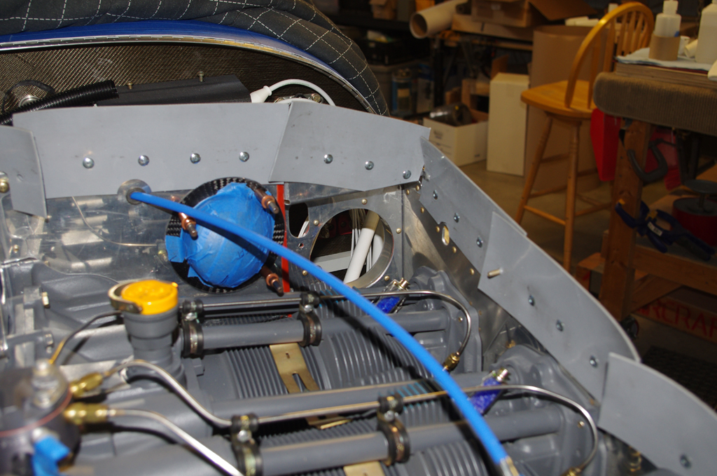
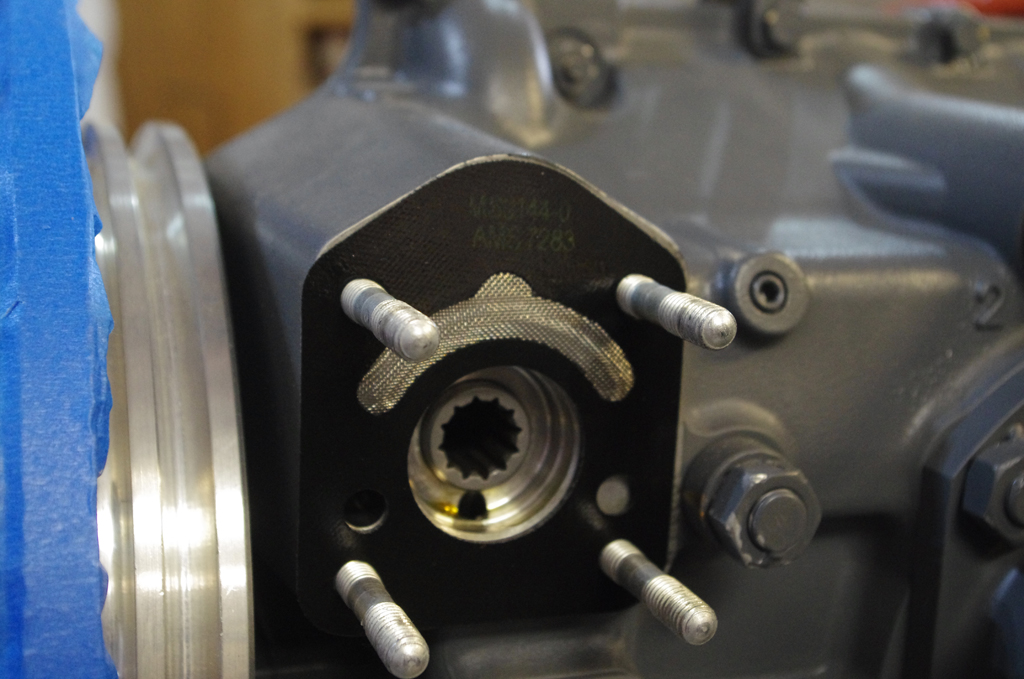
 Before fitting a special baffle around the prop governor, the simple gasket was replaced with one have a filter screen. Fitting the special baffle over the prop governor should help with air loss.
 The forward baffle seals were created with the default Vans material. On the right the distance between the prop governor and the upper cowl was measured with a piece of modeling clay.
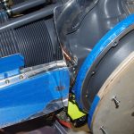
 This photo shows the final baffle seals around the prop governor.
 The right front baffle before and after the seals are pop riveted into place.
 Seals were measured, cut, and Pliobond for the lower cowl air inlets from the default Vans material.
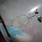
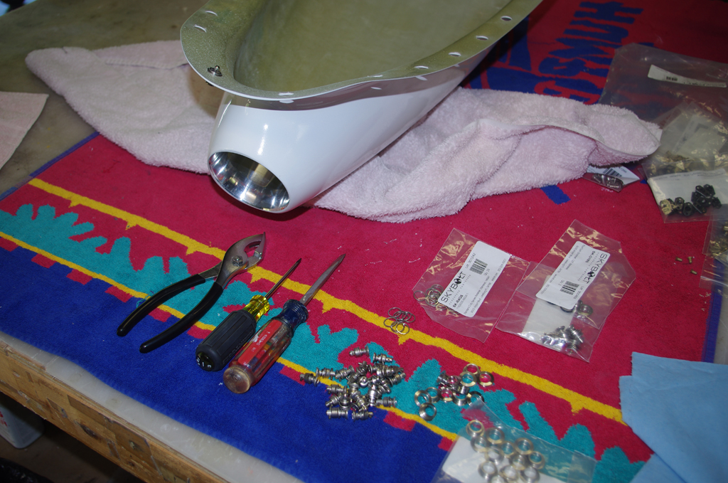
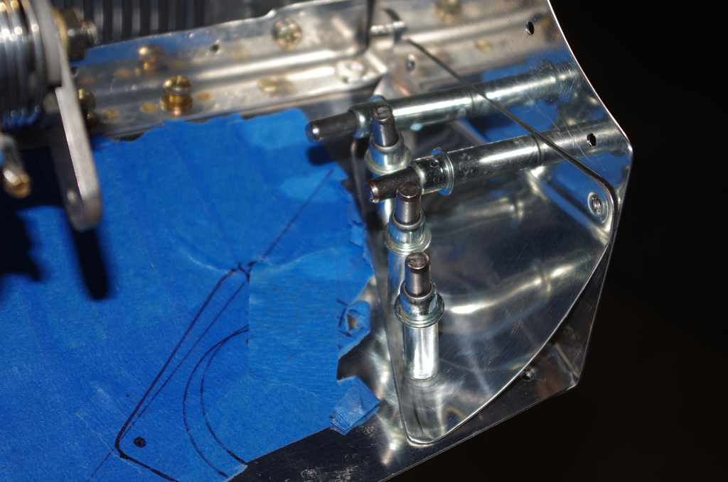
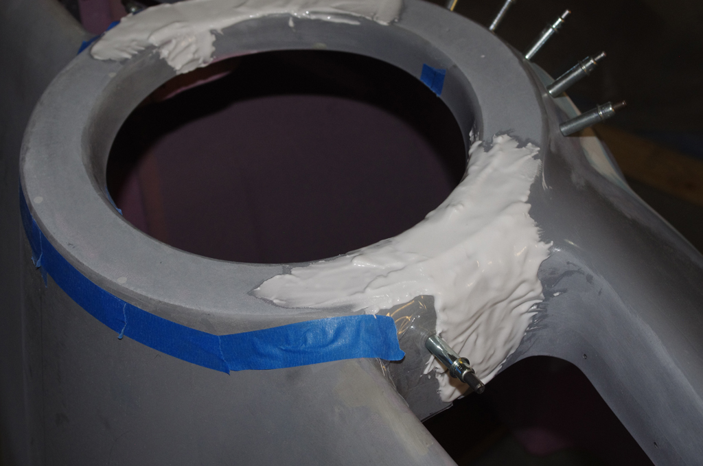
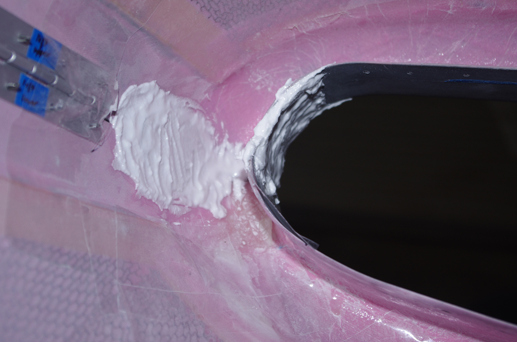
 Final fitting of the Aerosport pin retention blocks and applying resin/glass bubbles around the edges.
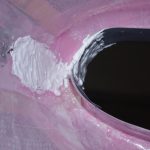
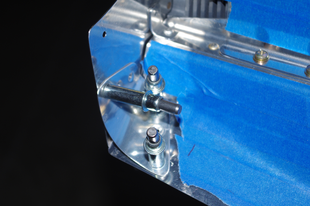
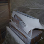
 Here the pin templates are shown from the interior space after raw application of just the resin/glass mixture. At right is the final configuration with four layers of 6oz fiberglass applied.
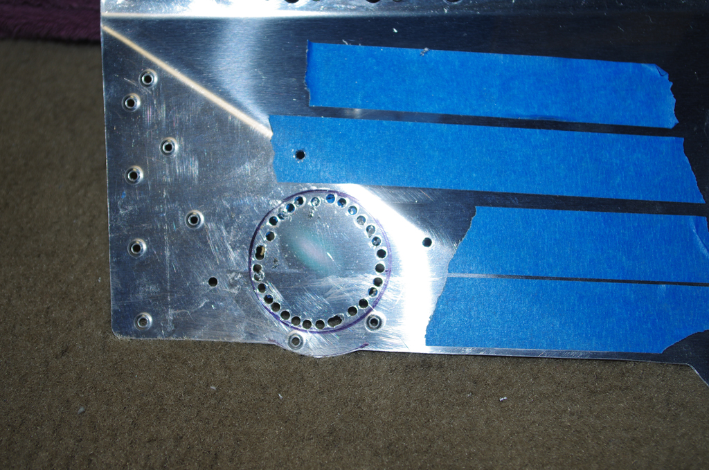
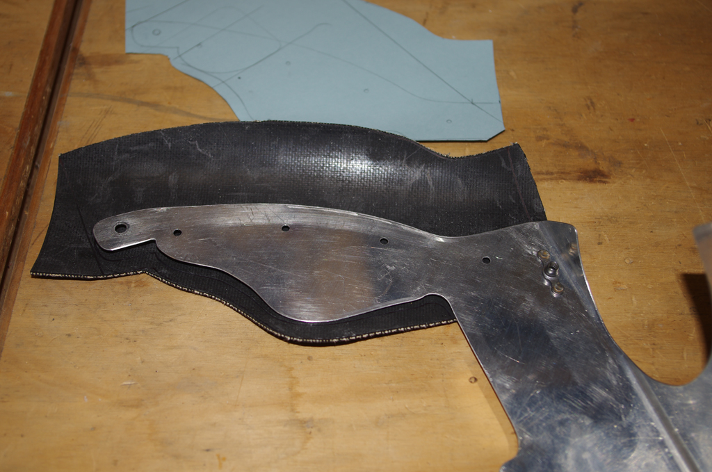
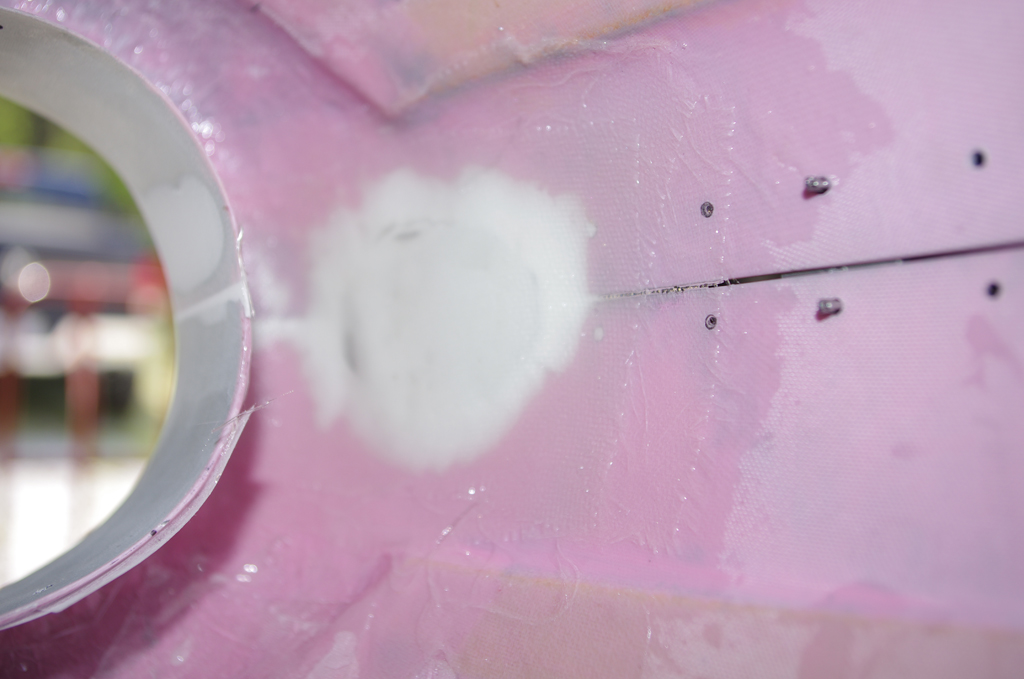
 Aluminum backer plates were fabricated for inside the pin block cavity. The plans did not call for these, but I wanted additional rigidity for this area. The plates were relieved in the middle for access to the side piano hinges.
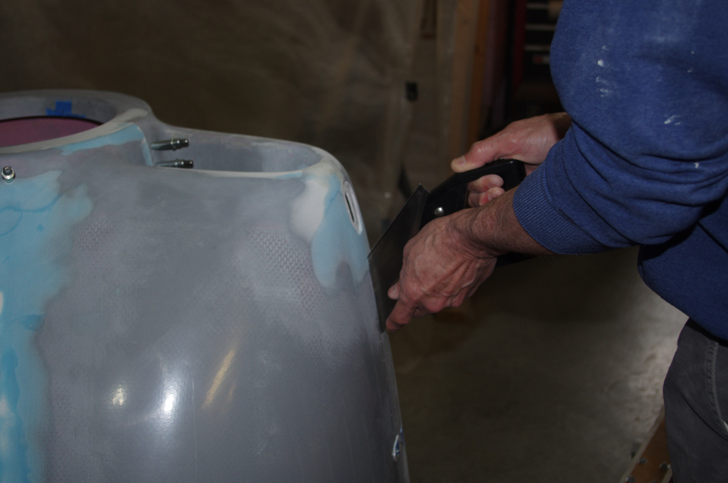
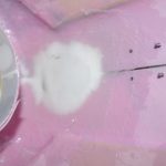
 The side fiberglass was also relieved to match the backer plates, then clecoed in place for a final coating of Superfil to create smooth edges. At right a kerfless saw separated the two cowl halves which had been joined by the pin retention cavity build process.
MISCELLANEOUS ITEMS
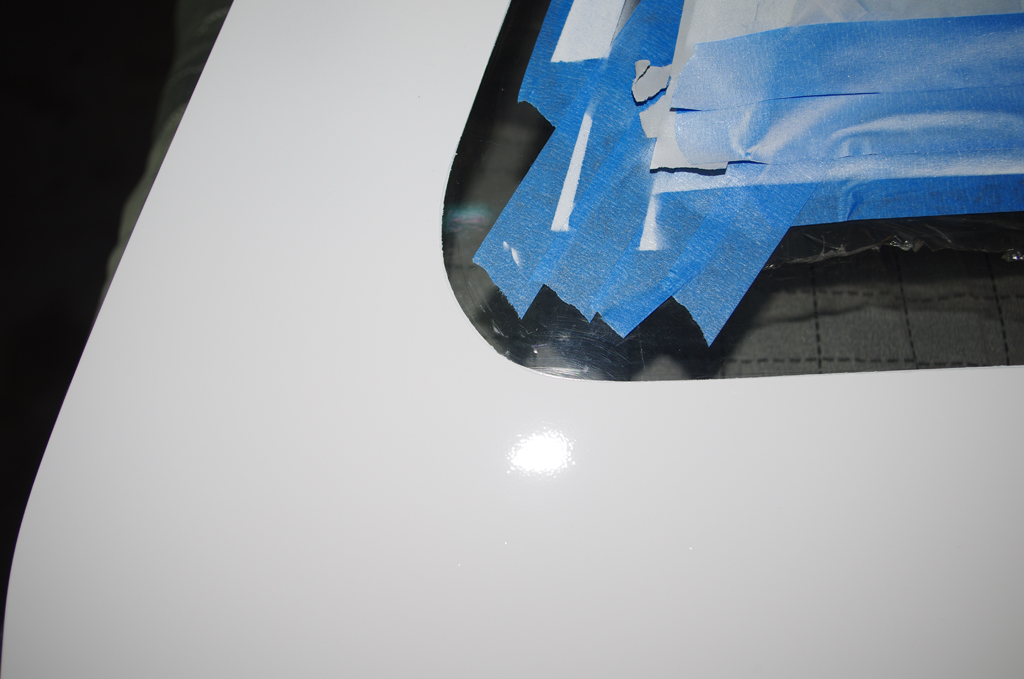
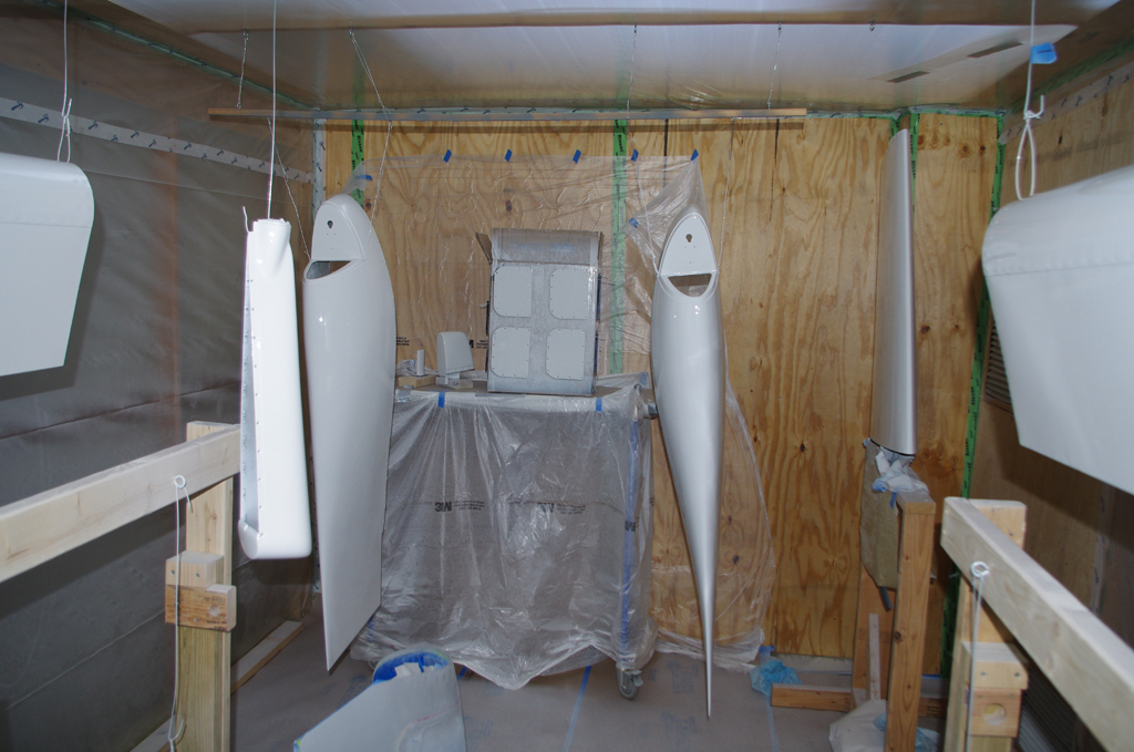
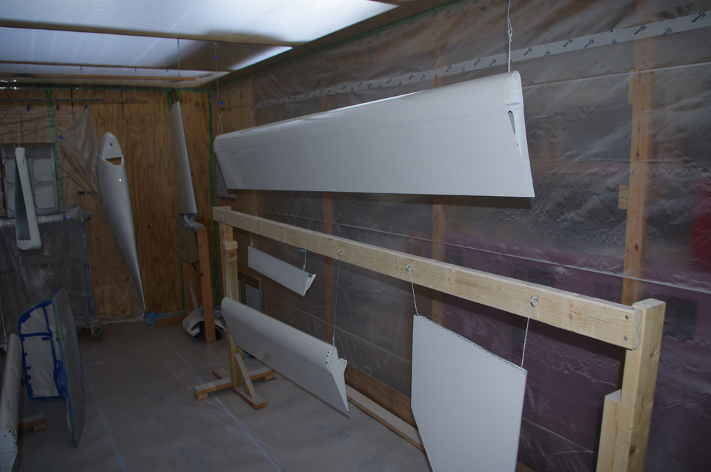
 More parts were painted base white…
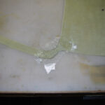
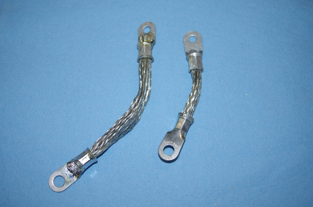
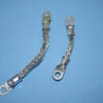 Headliner base repairs and new grounding straps…
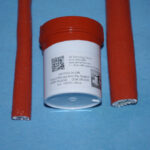
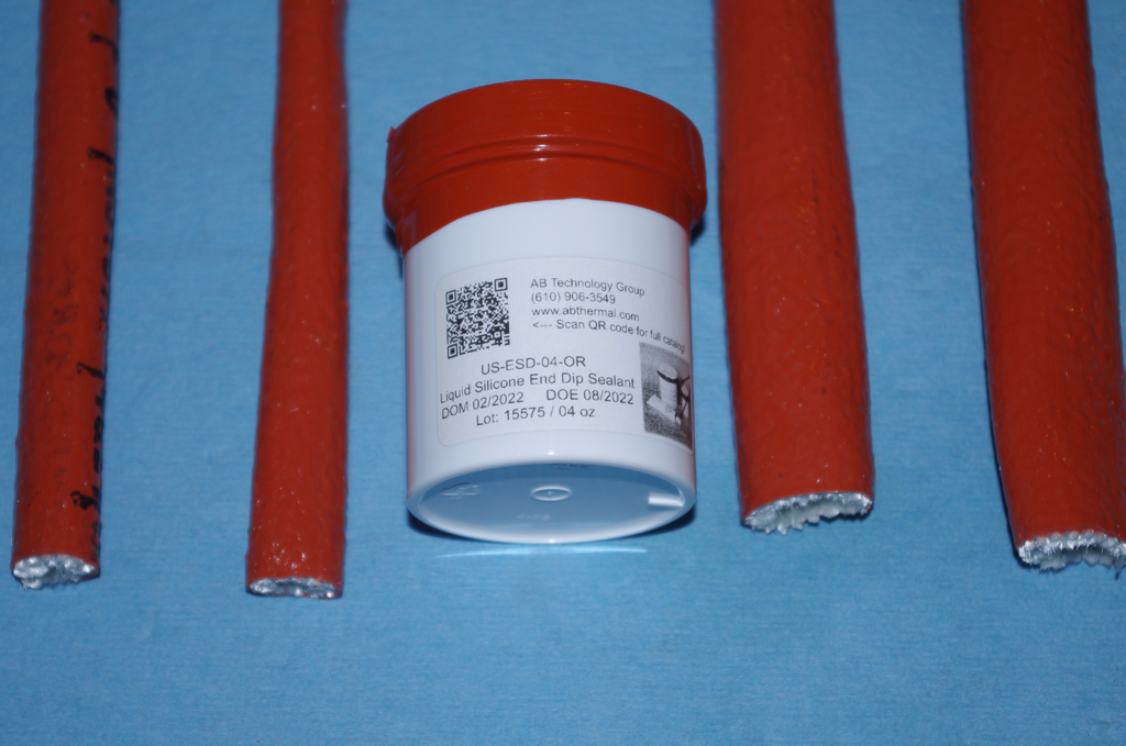
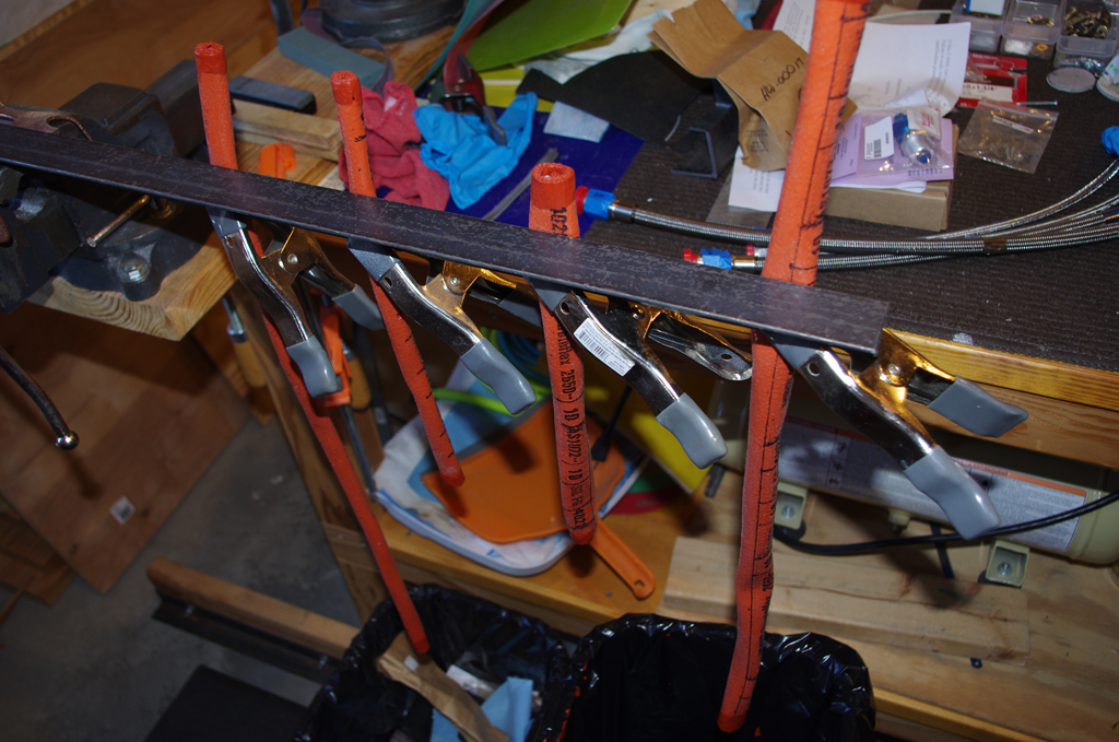
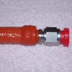
 Firesleeve dip for untreated oil and fuel lines…
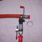
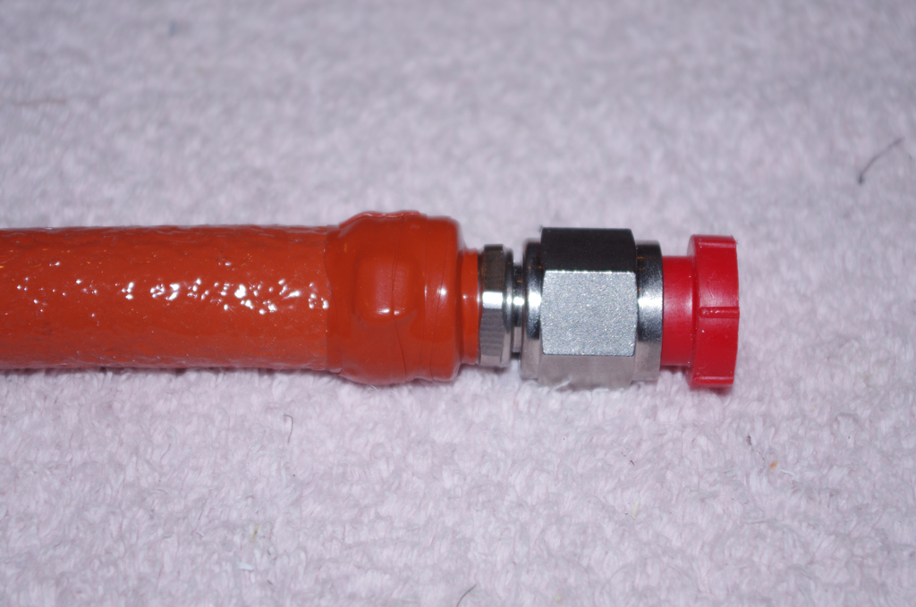
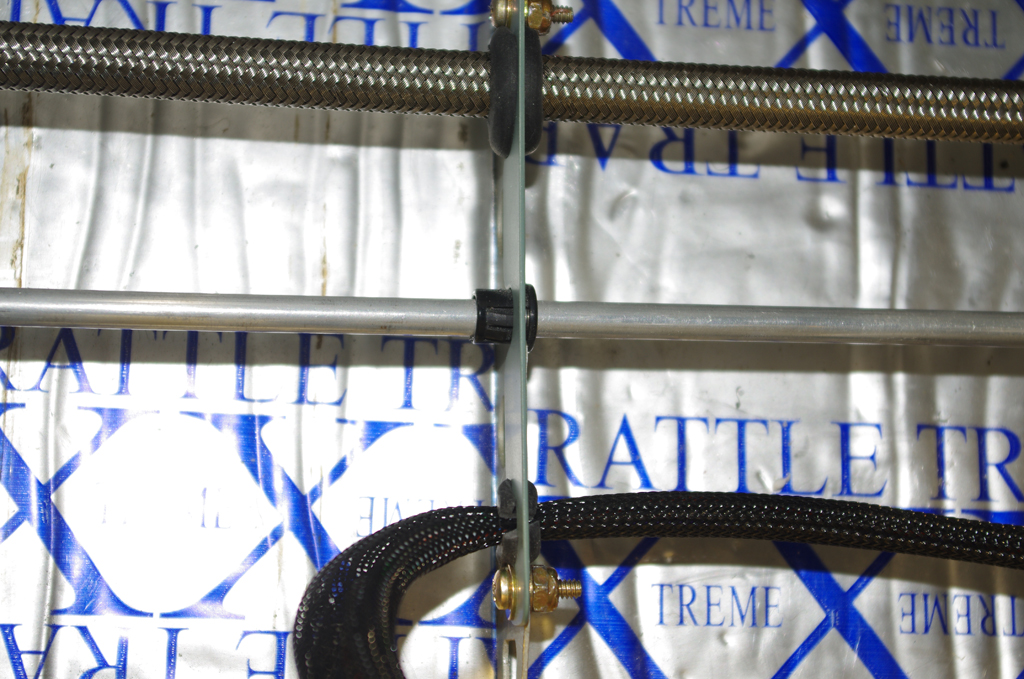
 Band-It Jr hose clamps and rescue tape wrappings for final line application (homemade firesleeve solution).
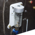
 Custom mounting bracket for Matco glass brake fluid reservoir and custom brackets for under-seat line security (fuel, brake, control stick wires)…
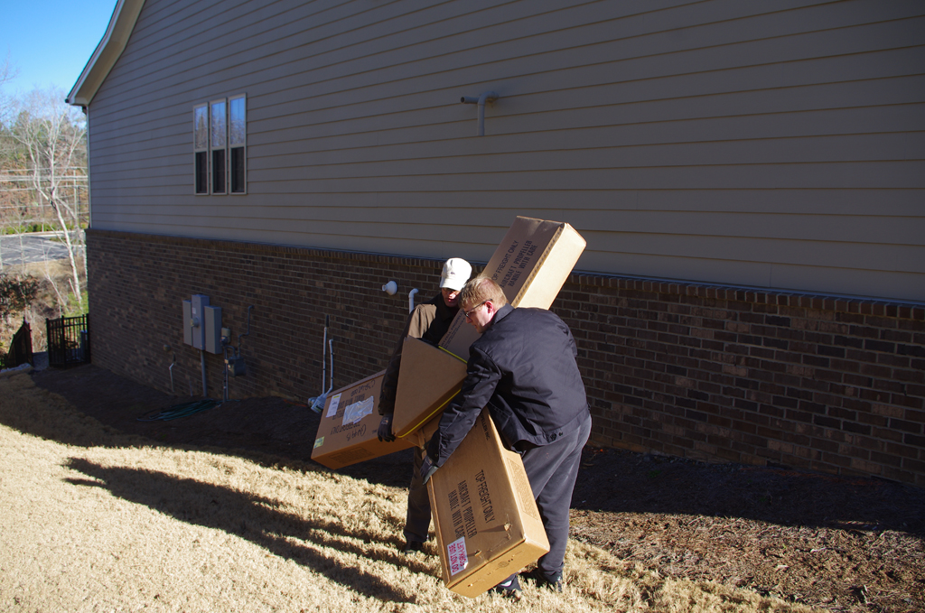
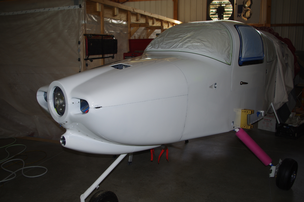
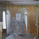
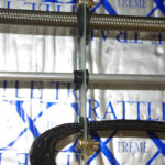
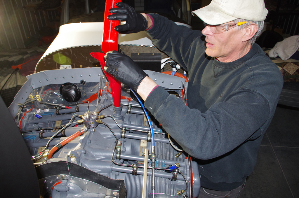
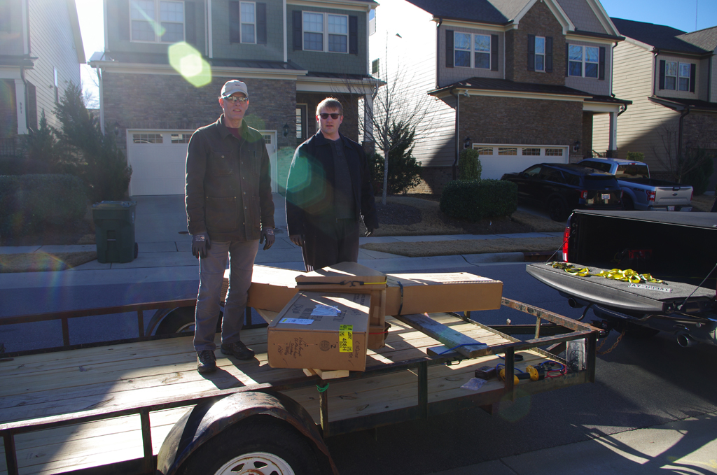 My son and I carried the propeller out of basement storage for transport to the airport.
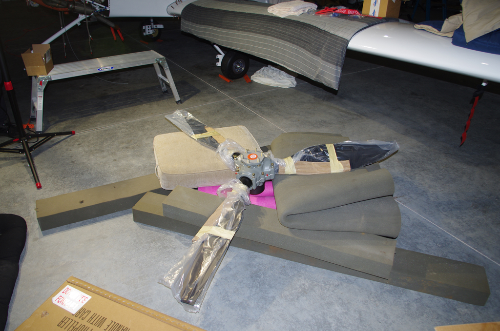
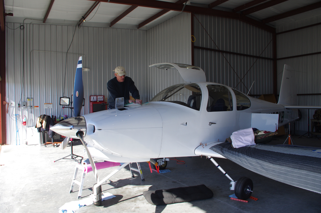
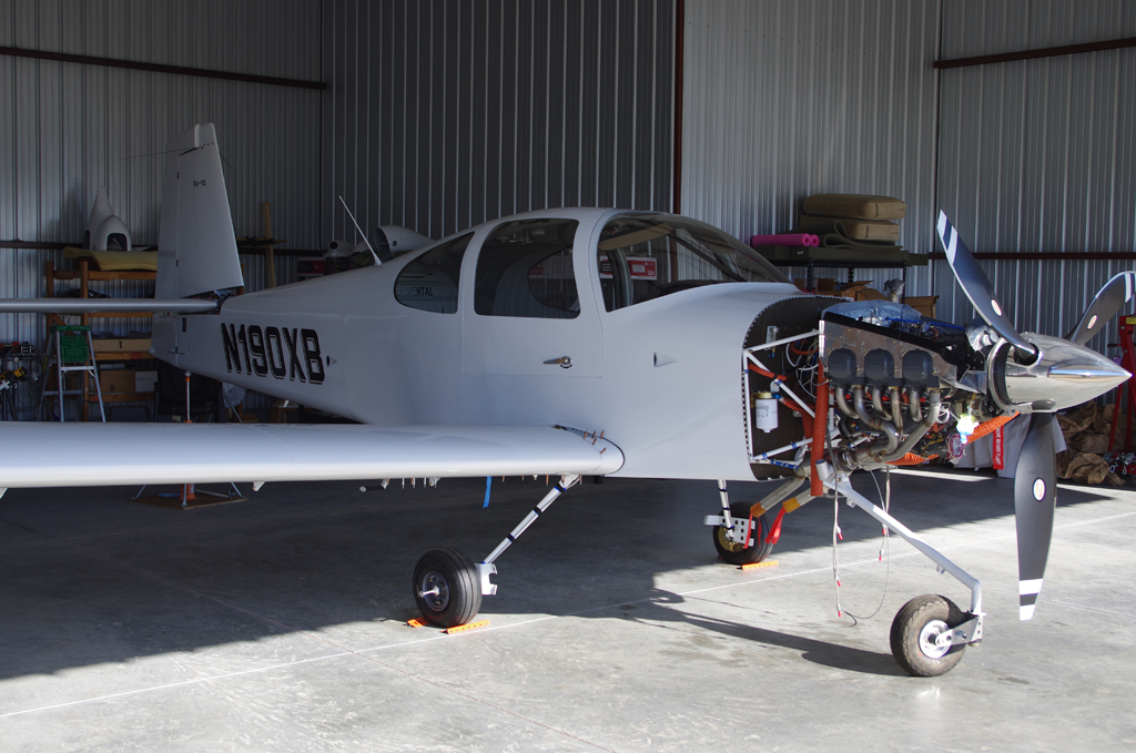 The unwrapped propeller on the floor was checked, then hung by Terry, Eric and I. Sorry no photos were taken during that process. Needless to say, everything went well and the prop looks great. Easily the best looking thing about the aircraft!
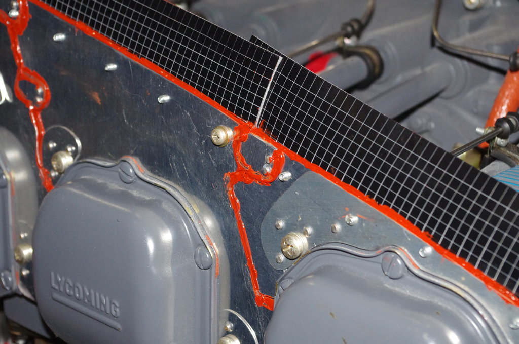
 High temperature RTV was applied to gaps in the baffling and between cylinder heads. The engine was then filled with 12qts of Aeroshell 100 mineral oil, which will be used for the 25-30hour engine break-in period.
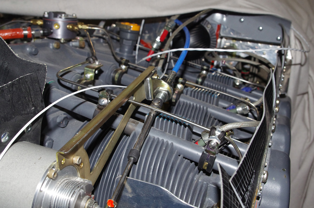
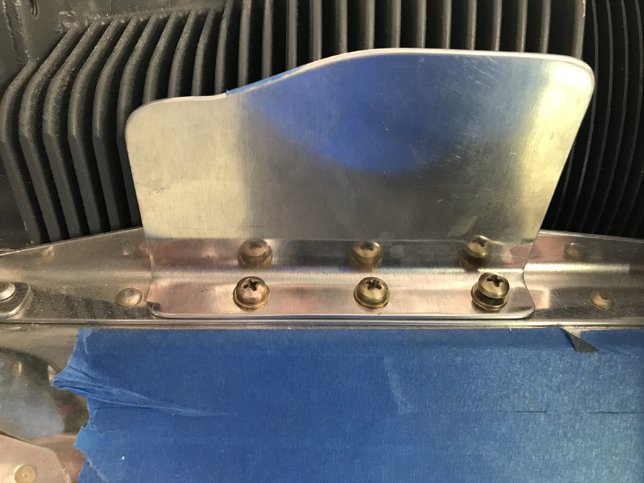 Final connections of the propeller governor cable and bracket adjustments were made. The air dams with their original heights were installed. These were later reduced in size after some initial flight tests were performed.
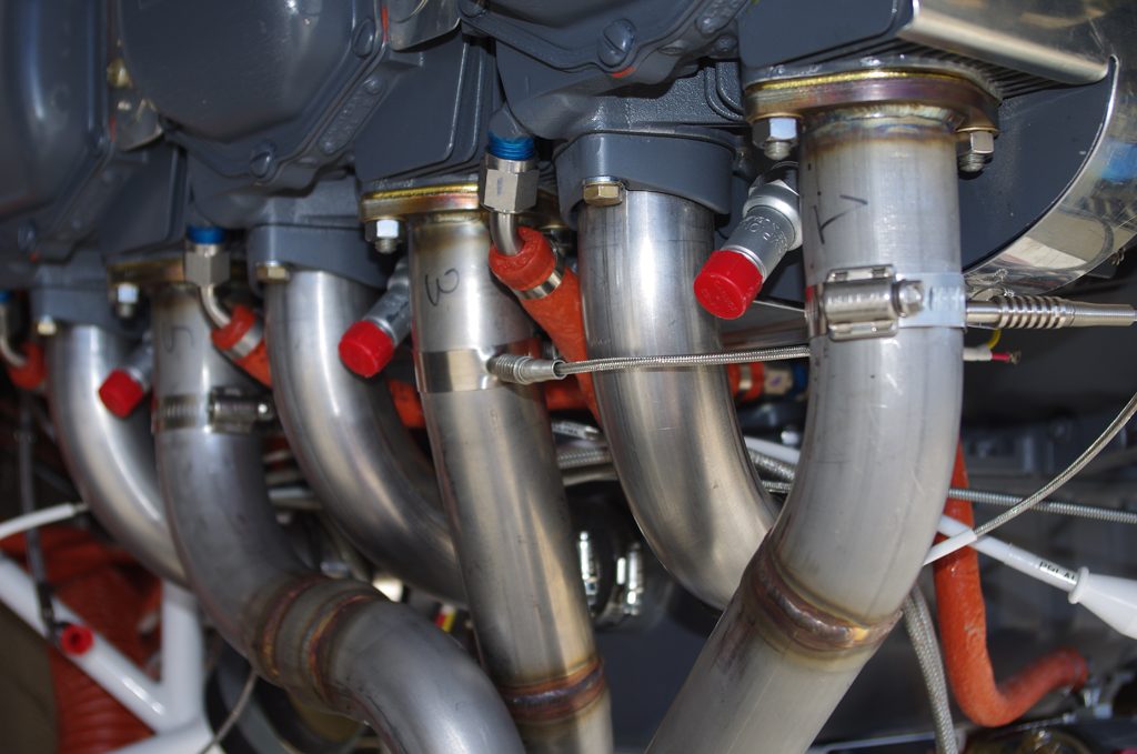
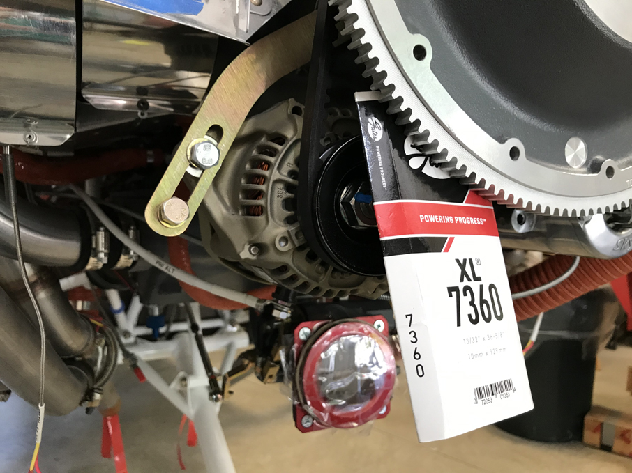 EGT probes were installed in the exhaust manifold, then bundled with their corresponding CHT probe wires. The alternator belt was tensioned and Safe-T-Wired secure.
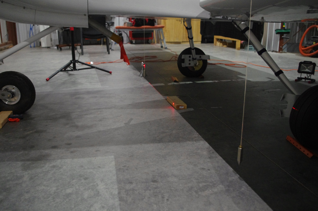
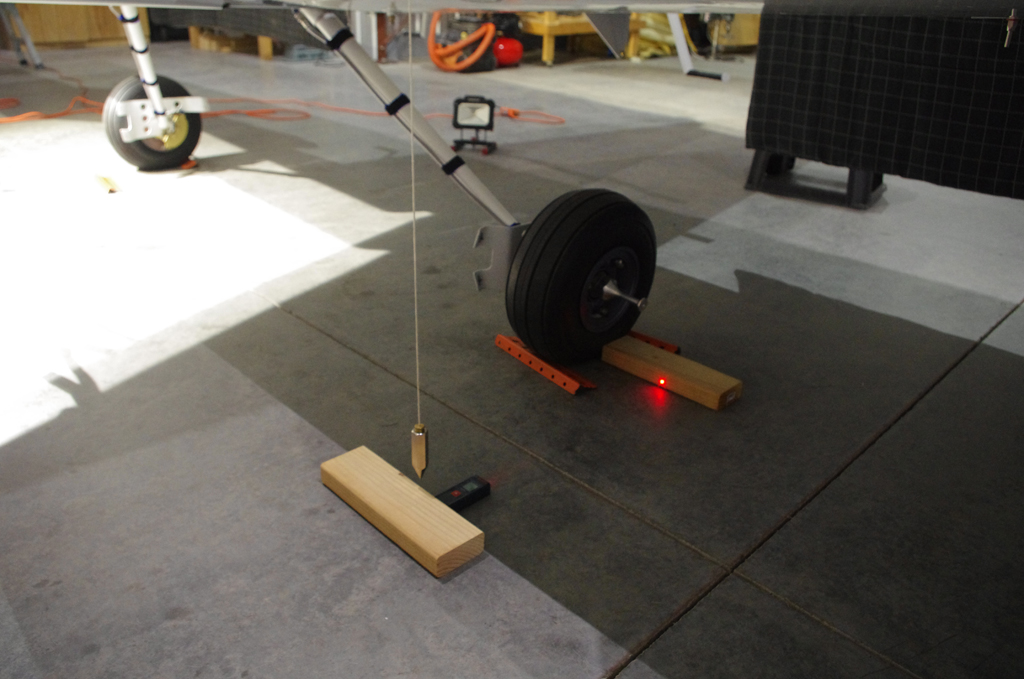 Measuring the leading edge of the wing provided a reference point for the CG calculations.
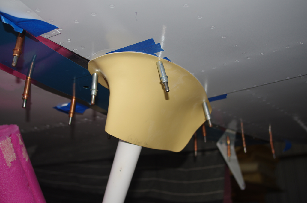
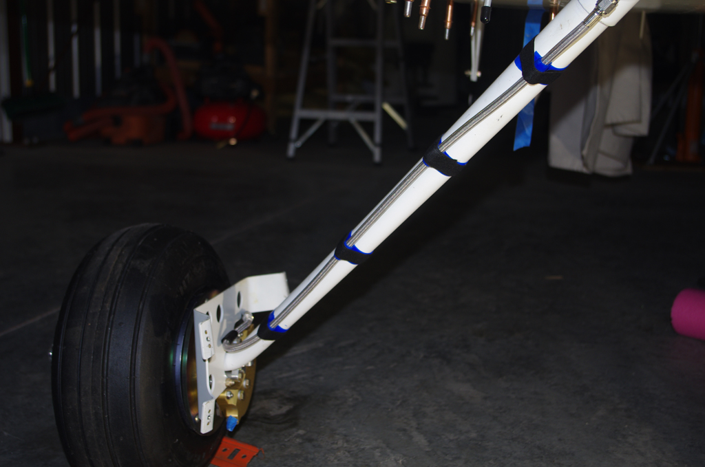 Intersection fairings for the gear legs were initially fit, then later painted and installed after the TS Flightlines stainless braided brake lines.
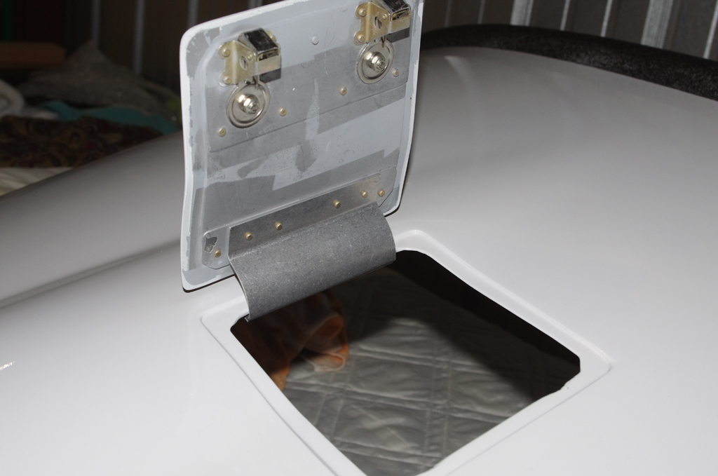
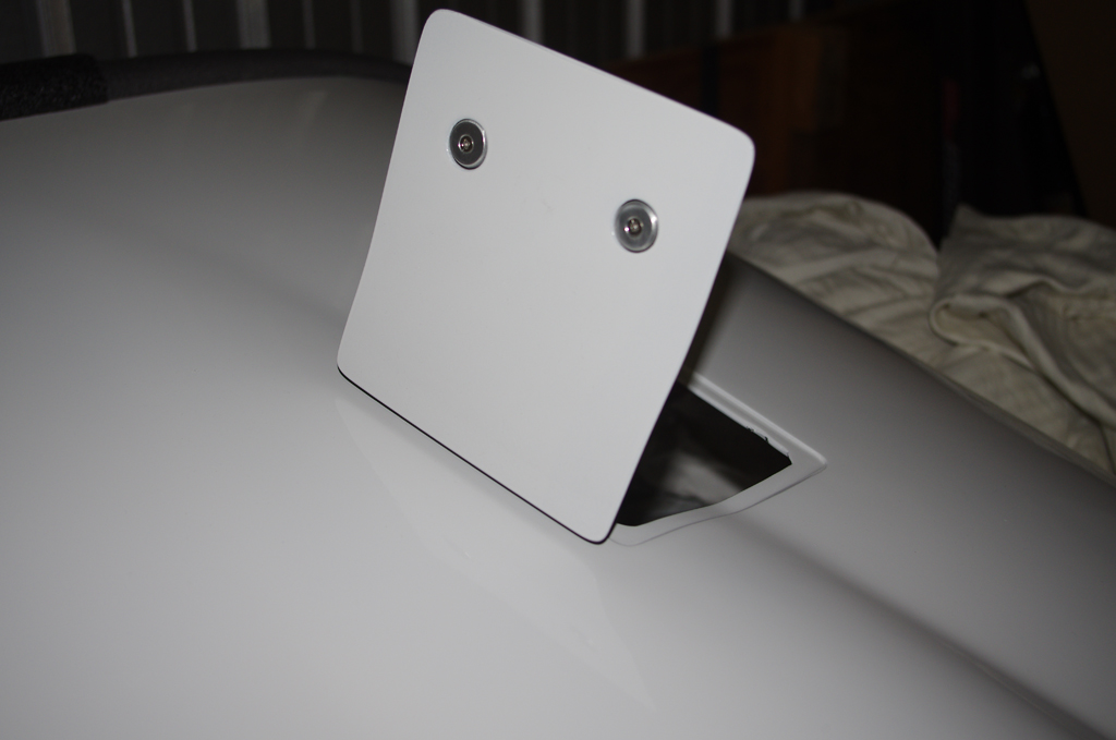 Final installation of the oil door with hidden hinge…
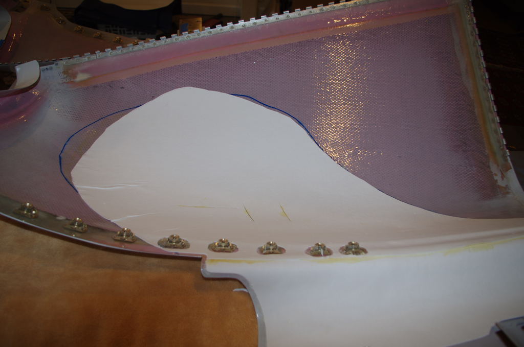
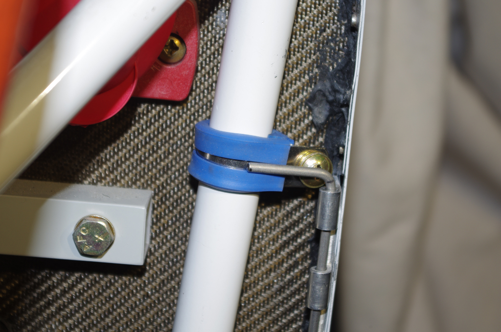 A 1/16″ ceramic mat was contact cemented in the lower cowl, then covered with Vans aluminum heat shielding. This combination should prevent the cowl paint from being scorched by the exhaust manifold heat. Lower cowl pins will be secured against these Adel clamps with tie wraps.
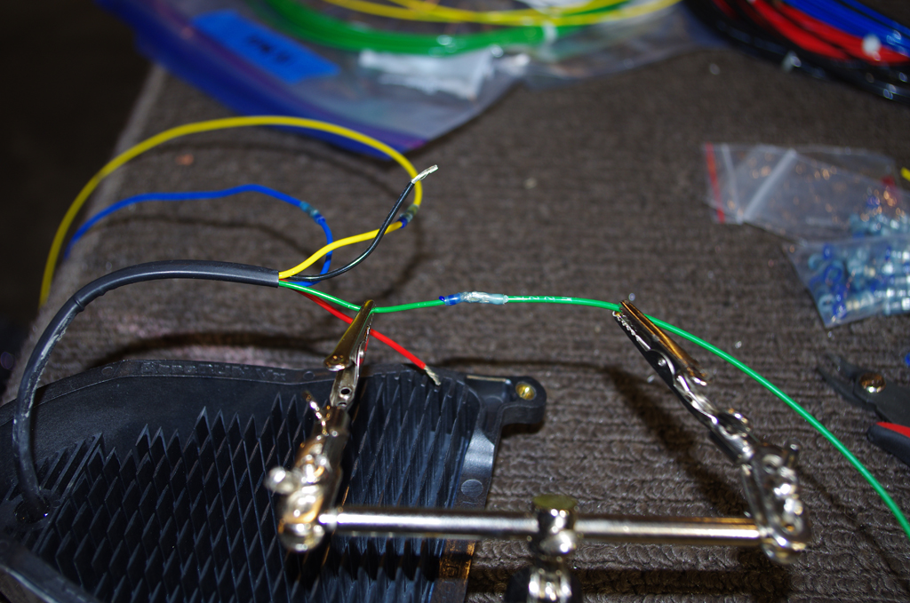
 Final wiring for AeroLED VX landing lights were Solder Sealed, then run through conduit to the wingtips.
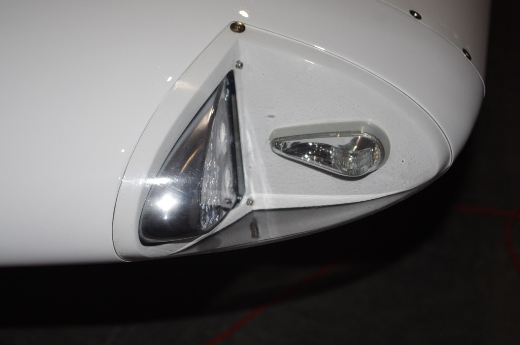
 AeroLED VX landing and NS position lights/strobes…
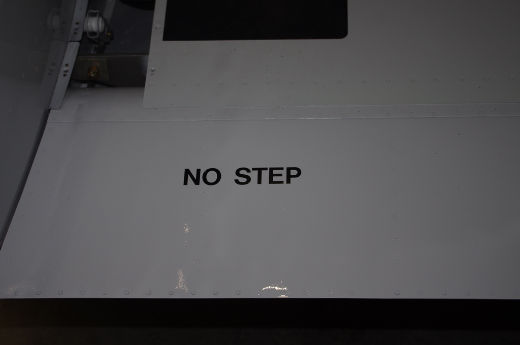
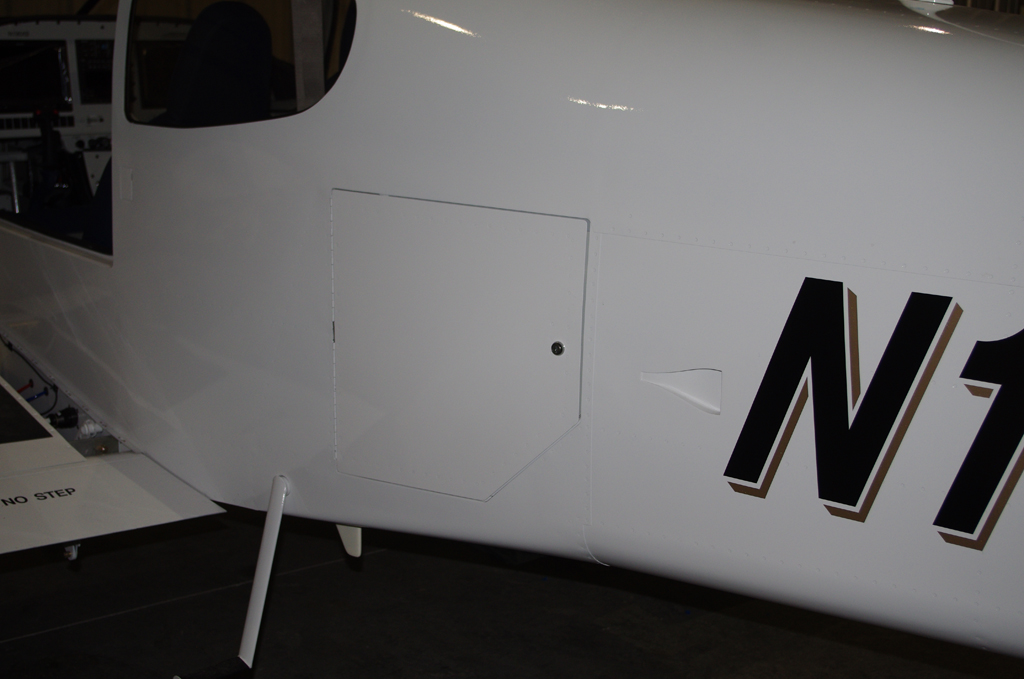
 Decals applied to flaps and doors…
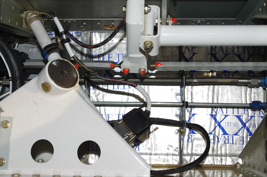
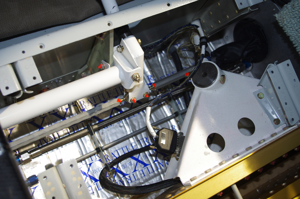 Wiring from control sticks to system buses used DB15 connections for easy maintenance or removal.
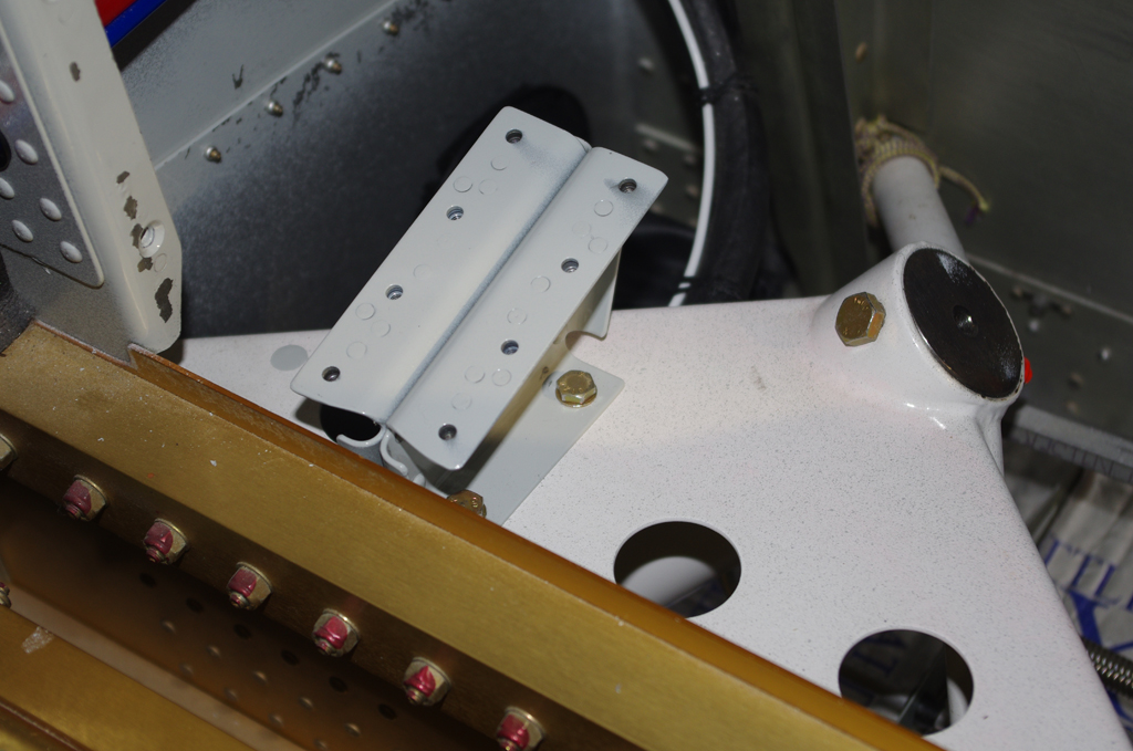
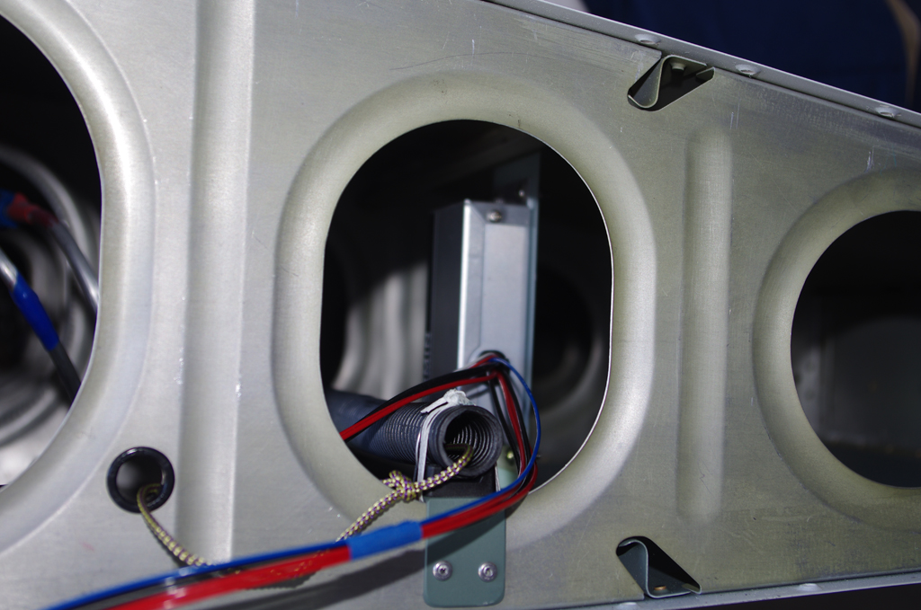
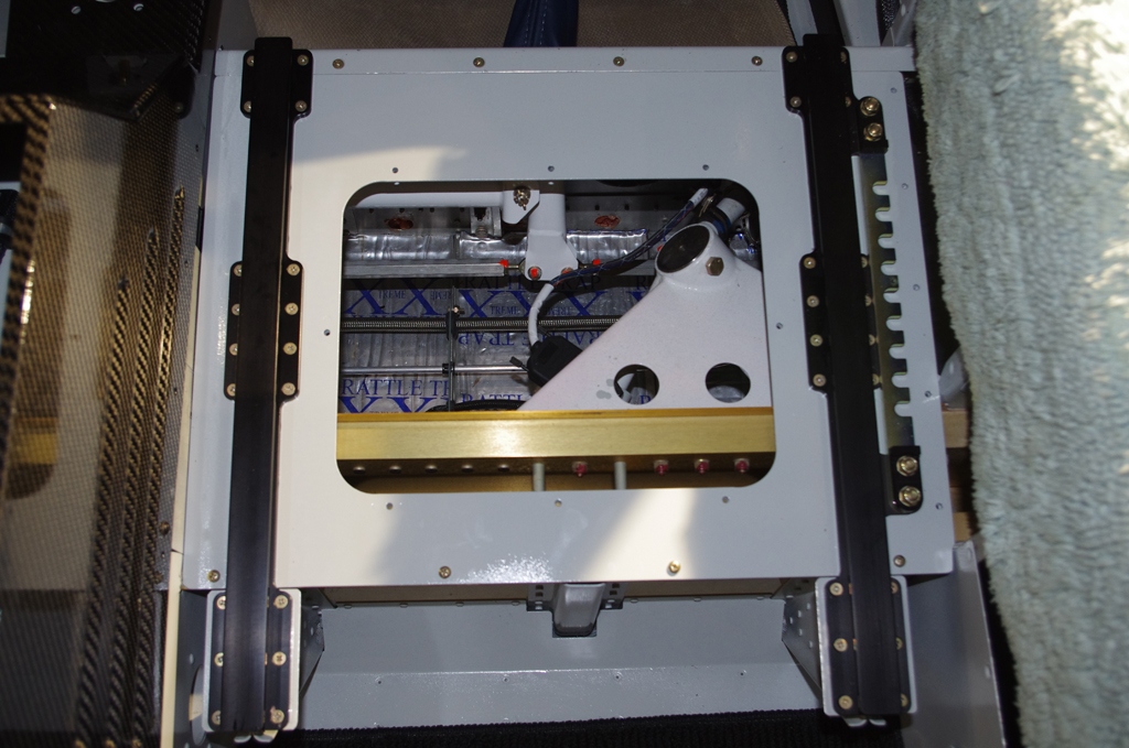 Ground wires were covered in thick rubber fuel lines to prevent chaffing, then seat pans were installed.
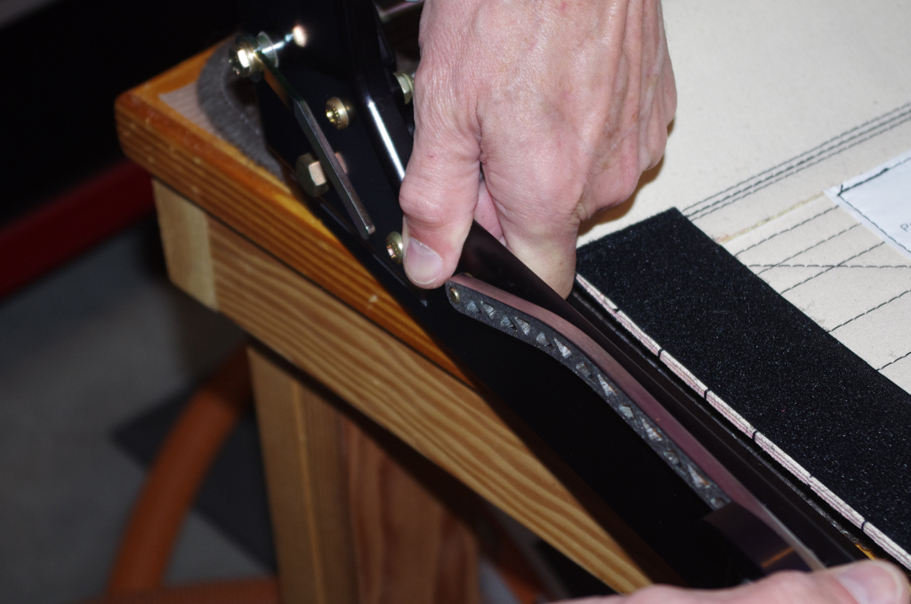
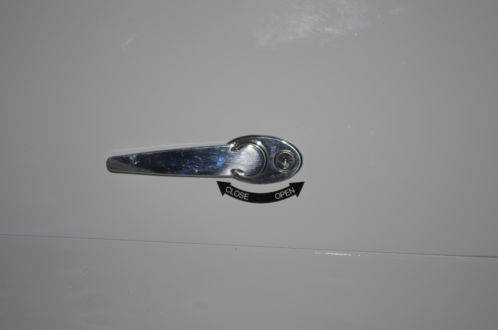
 Aerosport auxiliary seat handles were installed for easier operation. Then final inspection and review of everything to date.