Category Archives: Section 45, Cabin Doors And Transparencies

Cowl Baffling (3) and Miscellaneous

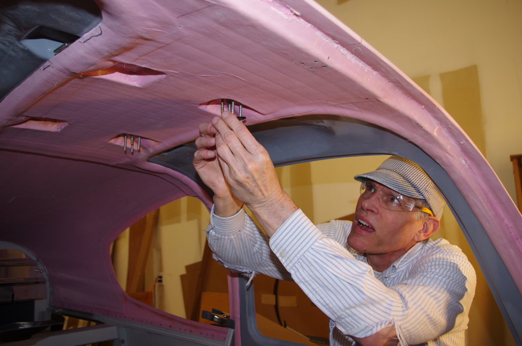
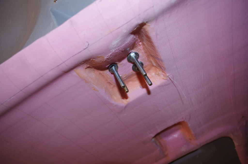
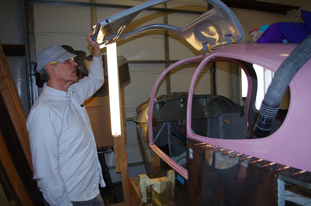
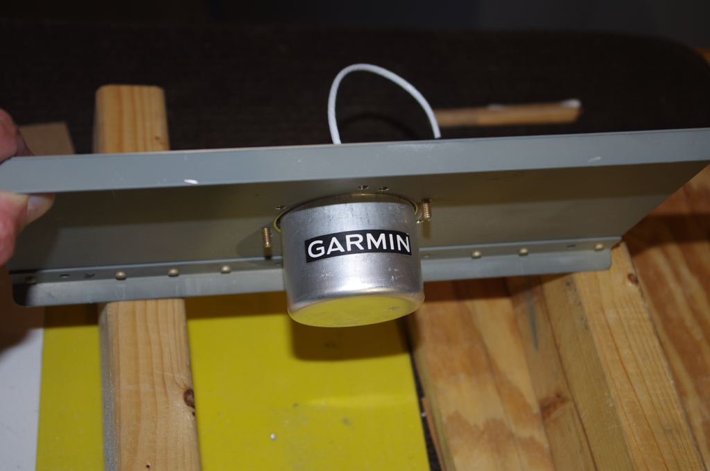
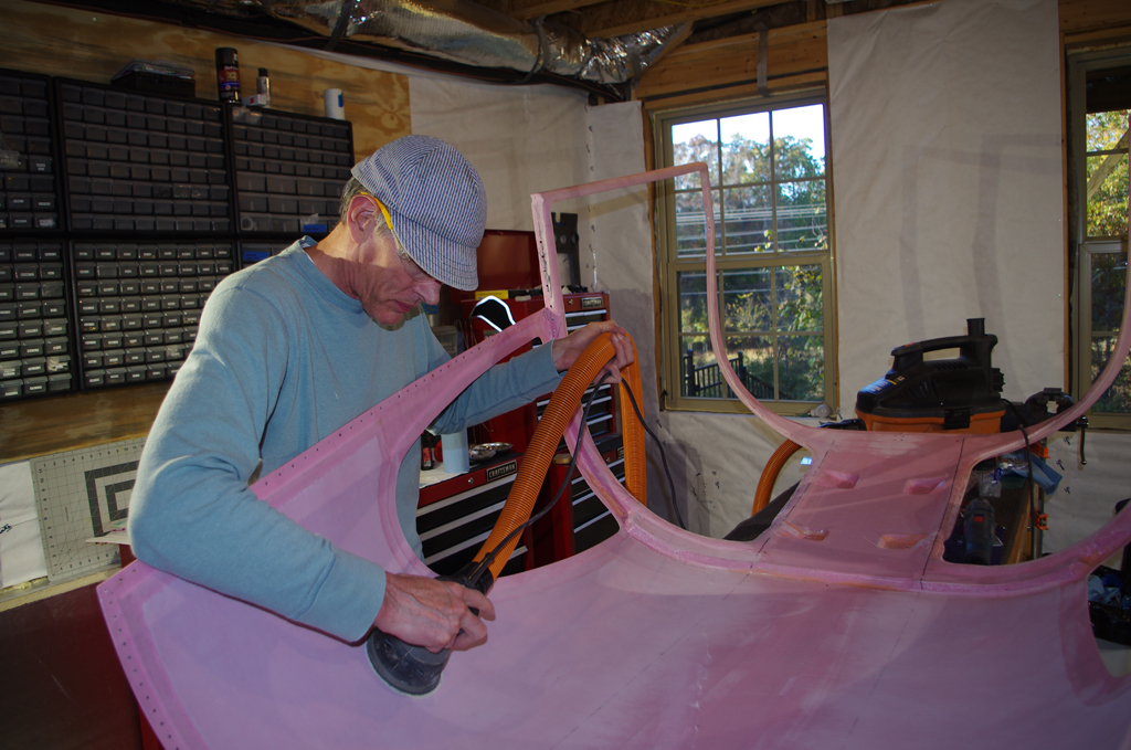
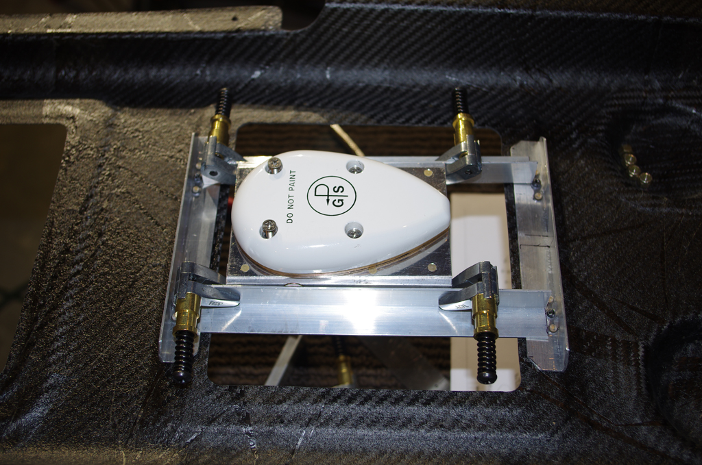
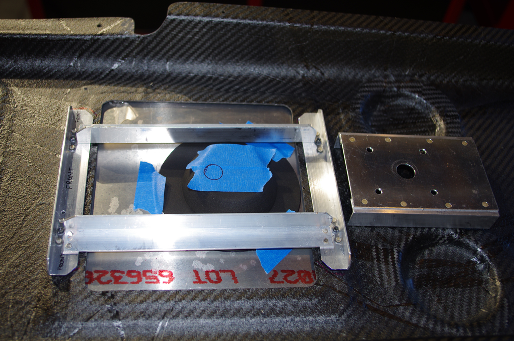
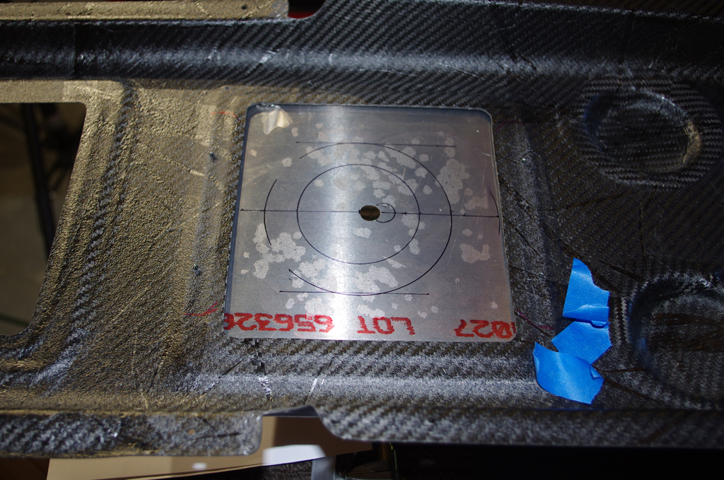
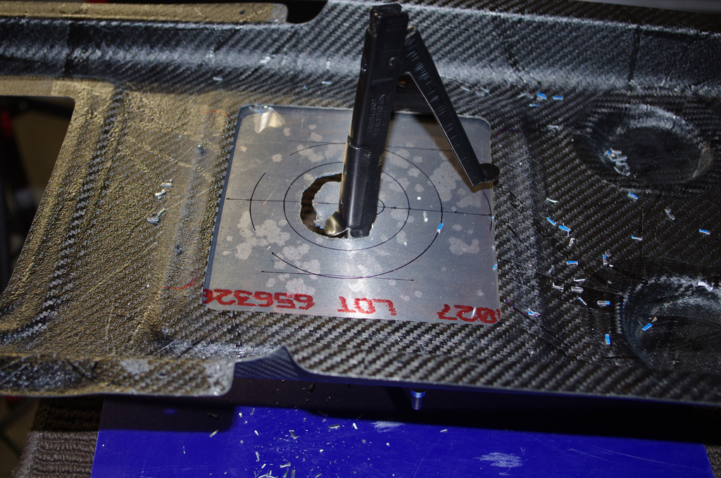
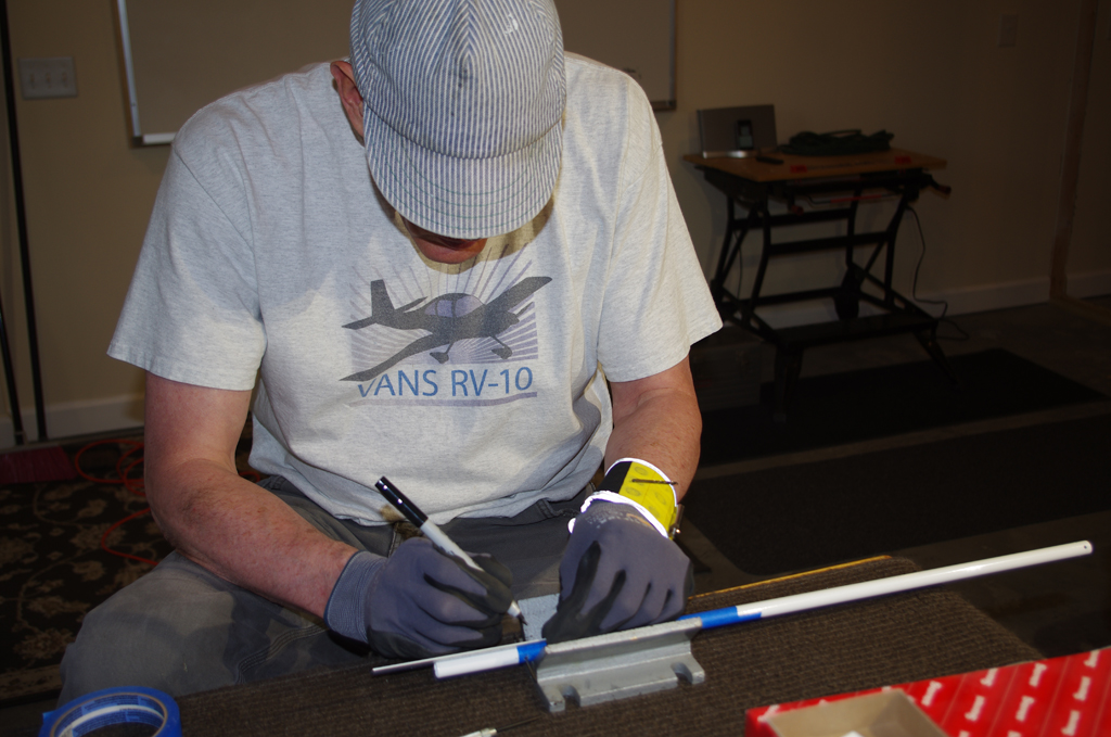
The cowl attachment points, pins and finalized baffling were performed throughout the last three month period as time permitted and was available between paint/prime sessions.

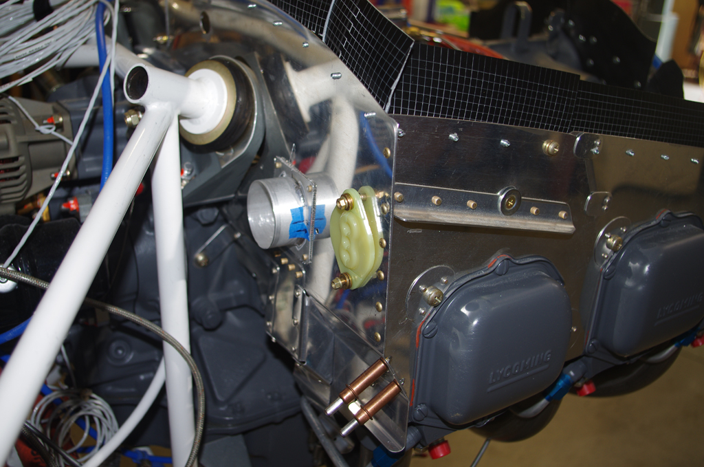
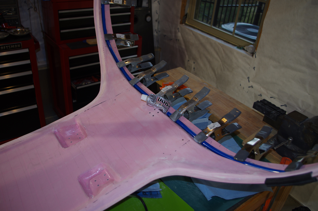
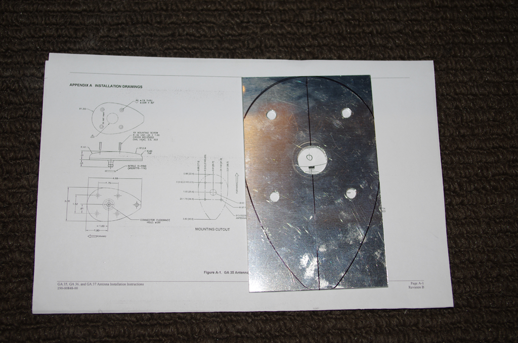
Many RV10 builders have reported the #5 cylinder chronically has the highest CHT temperatures – mainly due to the lack of airflow over the cylinder head.  One of the solutions mentioned in the forums is apply the RV14 baffle mod to correct this situation.  Here the mod is laid out and provisionally fit on the standard right-rear baffle.


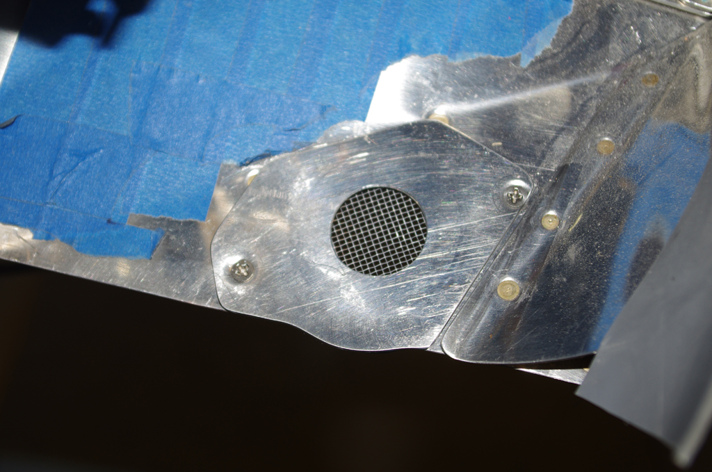
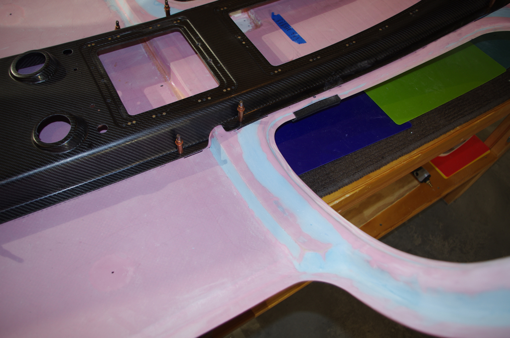
These photos show front and rear views of the installed RV14 mod.  Note the carbon fiber motor mount covers from Aerosport Products.


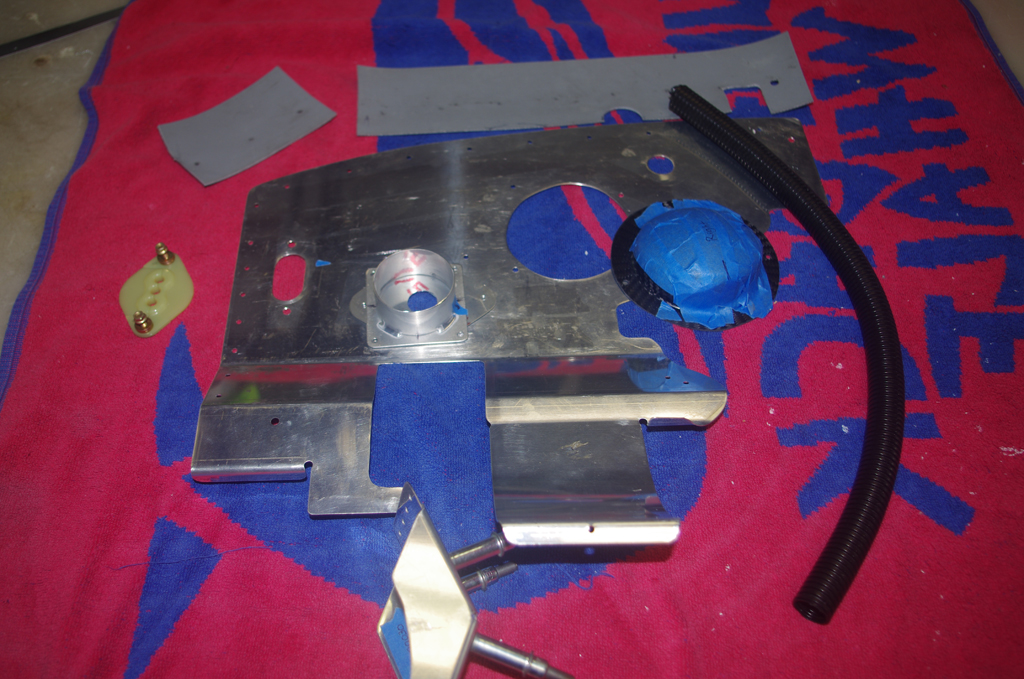
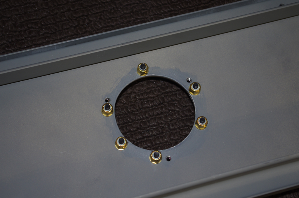
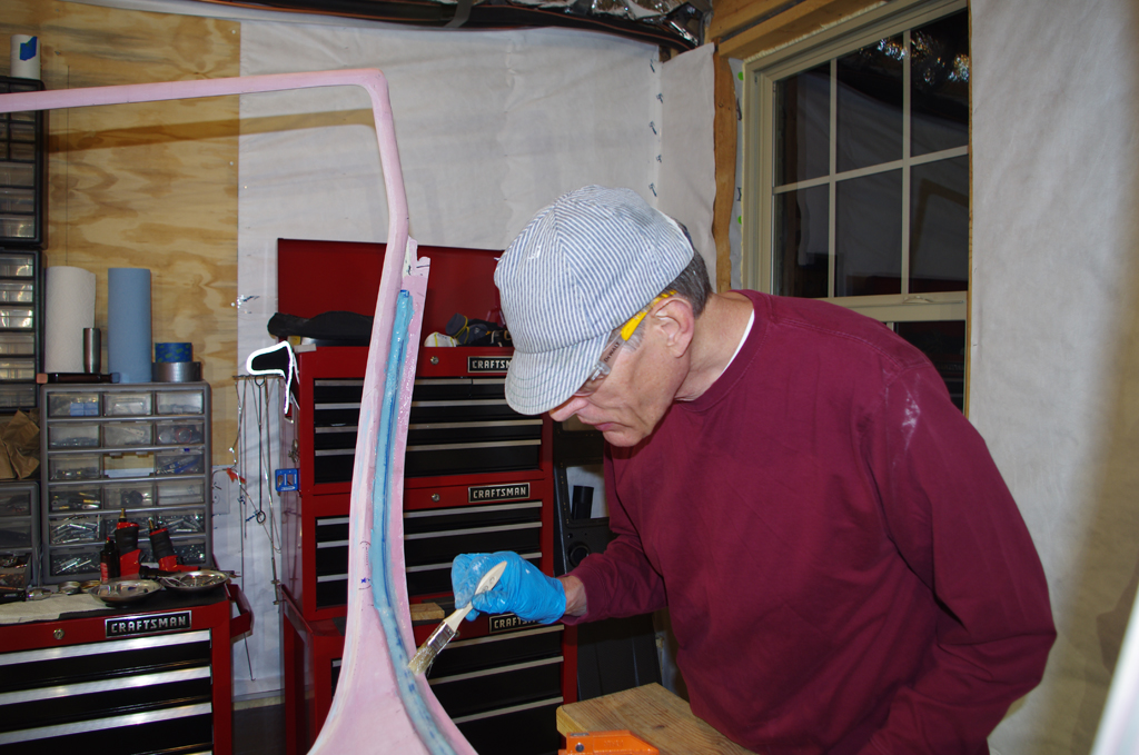
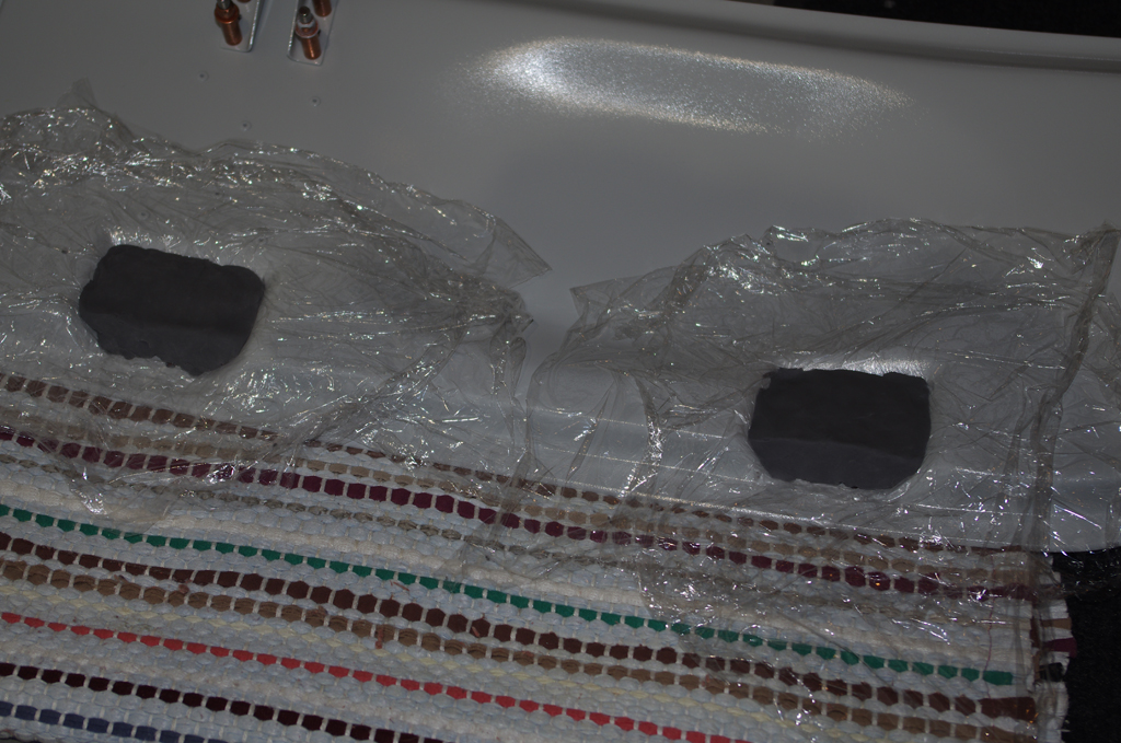
Another issue reported by many builders is the extreme heat generated by the heater muff during normal operations. One solution is throttle the intake air flowing to going to the heater access tubes.  I added restricting plates to the front and rear heater inlets which can be removed by loosening only two screws..  The volume of air going through these openings can now be easily adjusted.


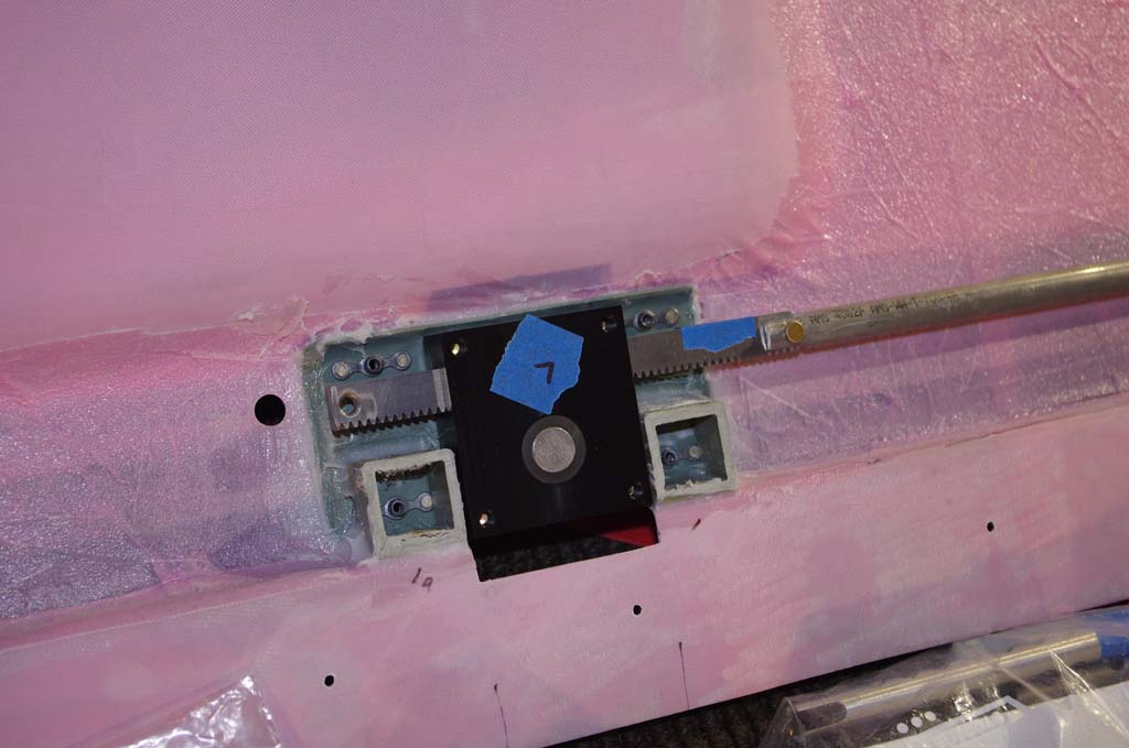
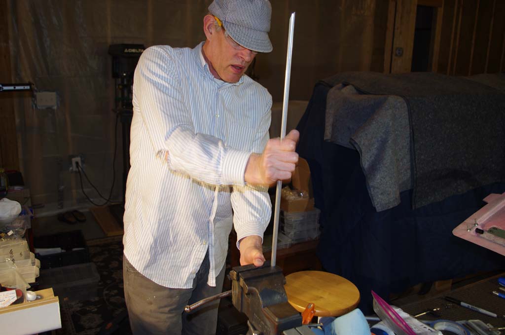
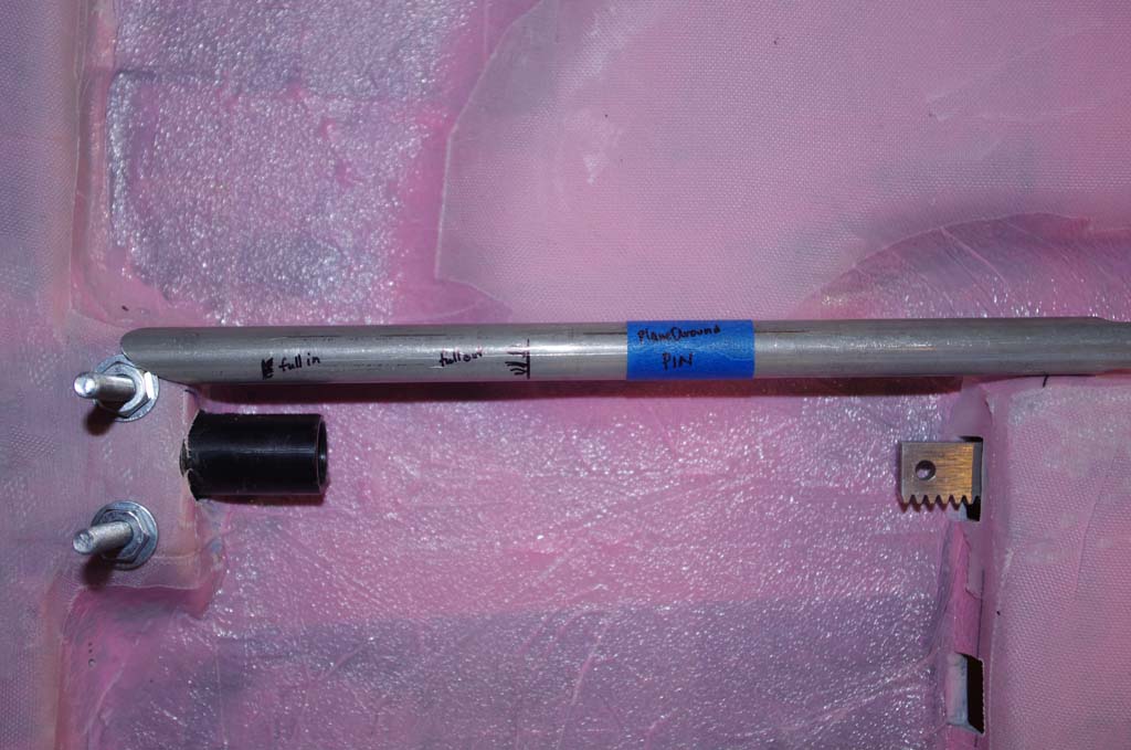
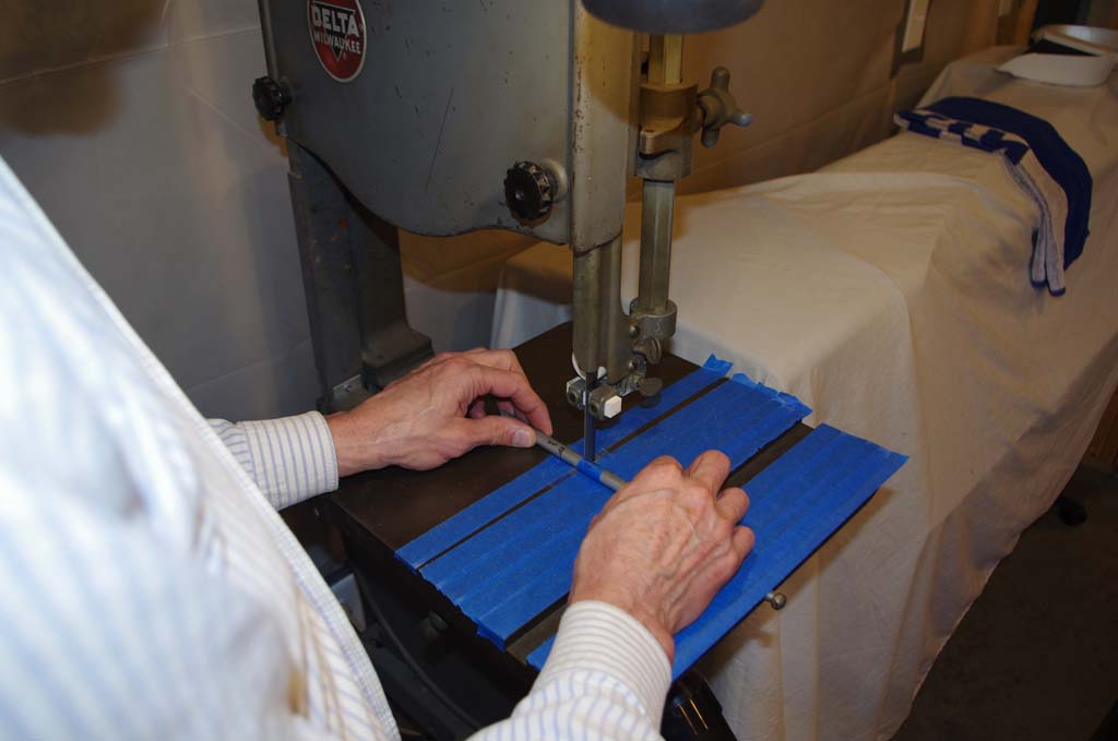
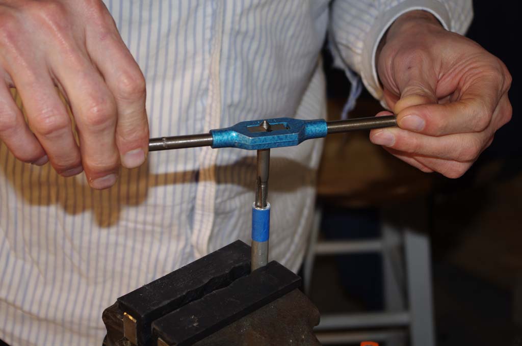
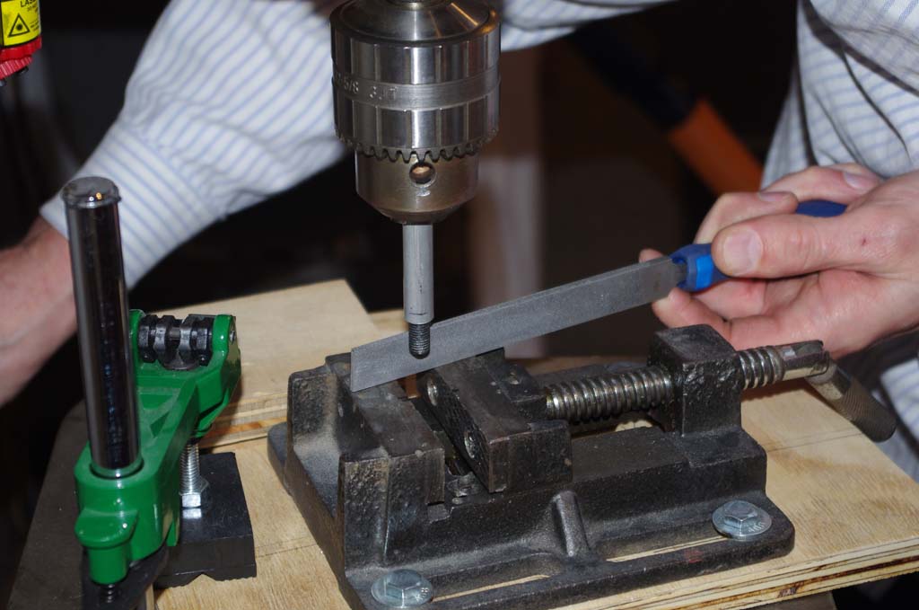
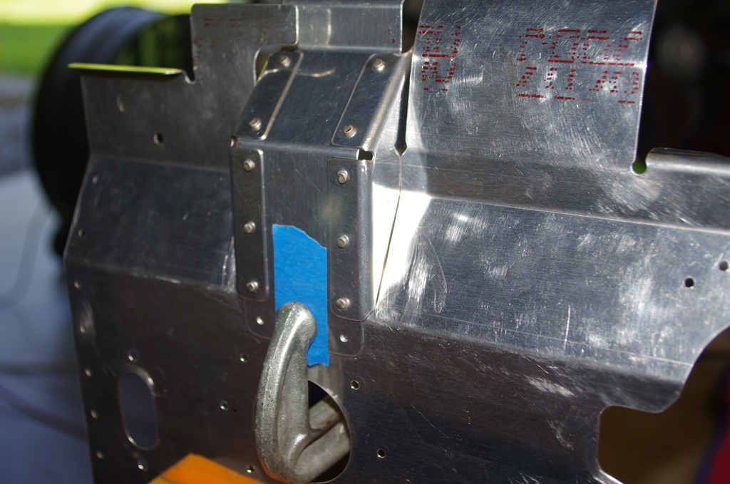
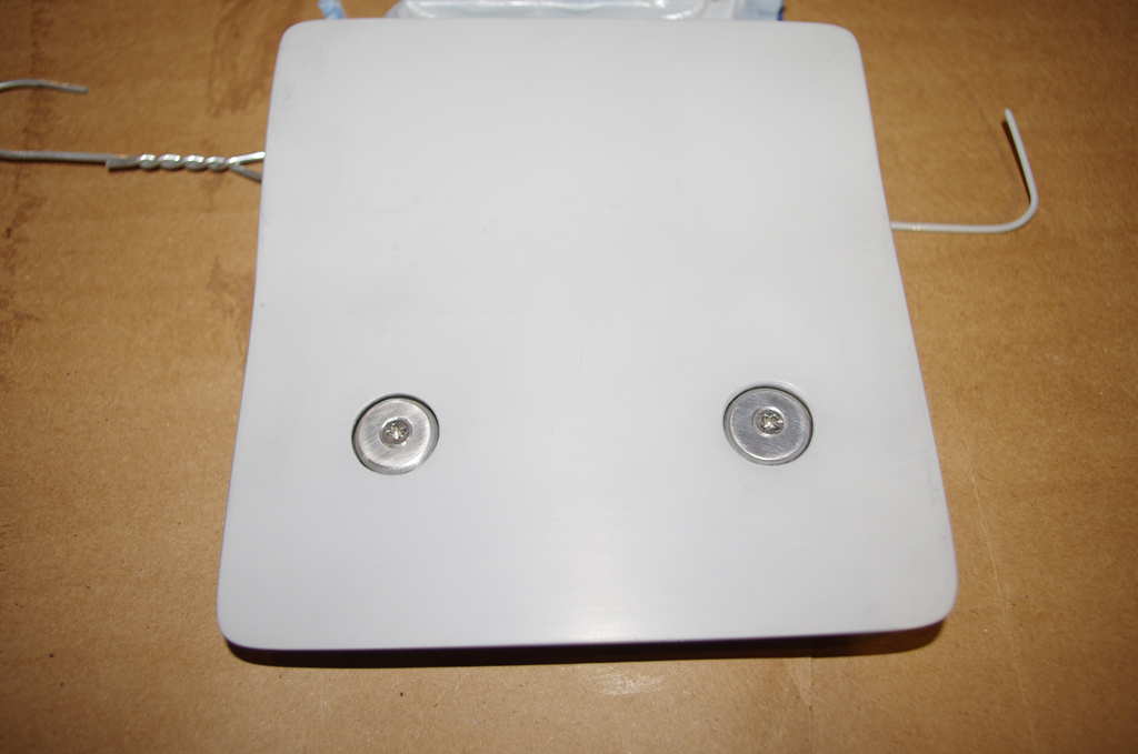
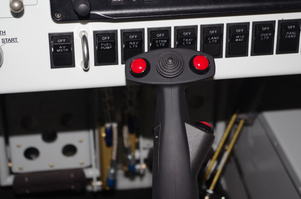
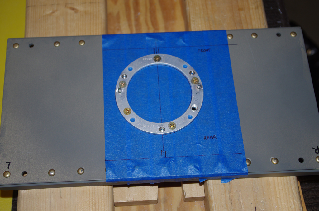
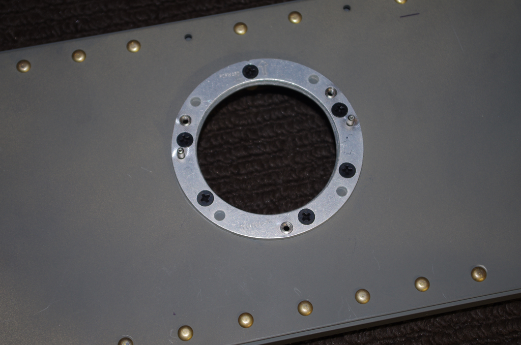
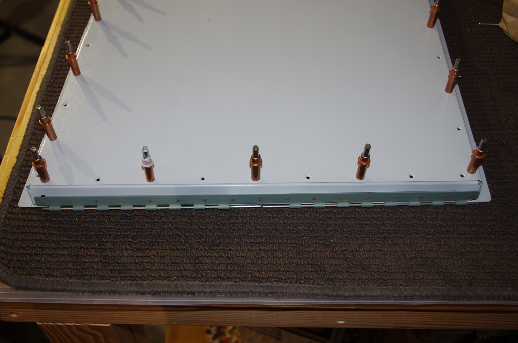
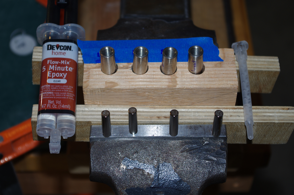
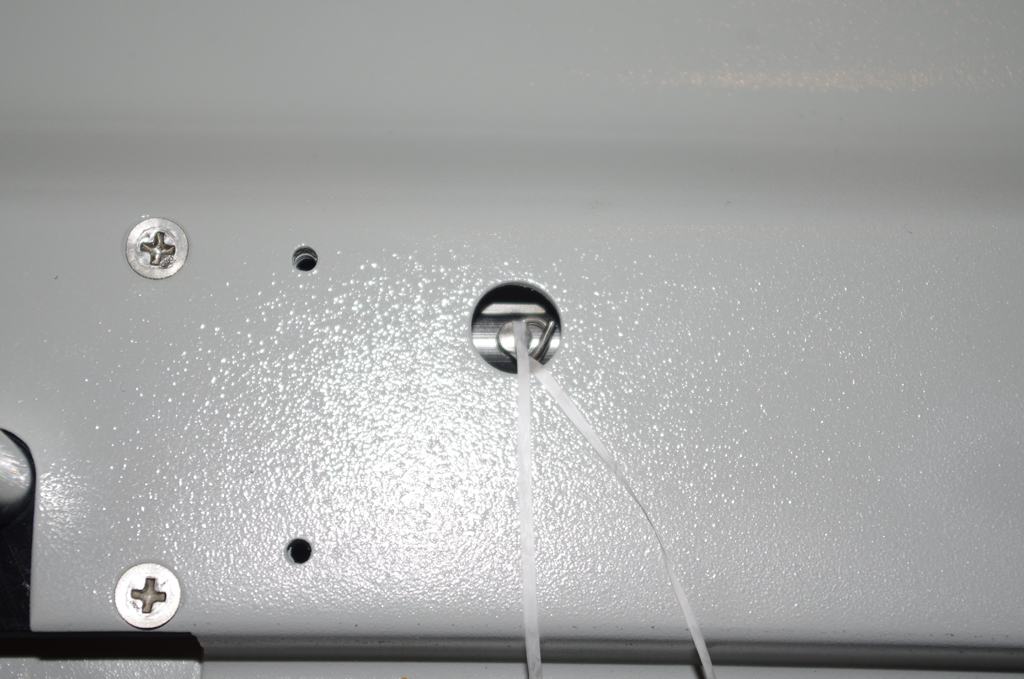
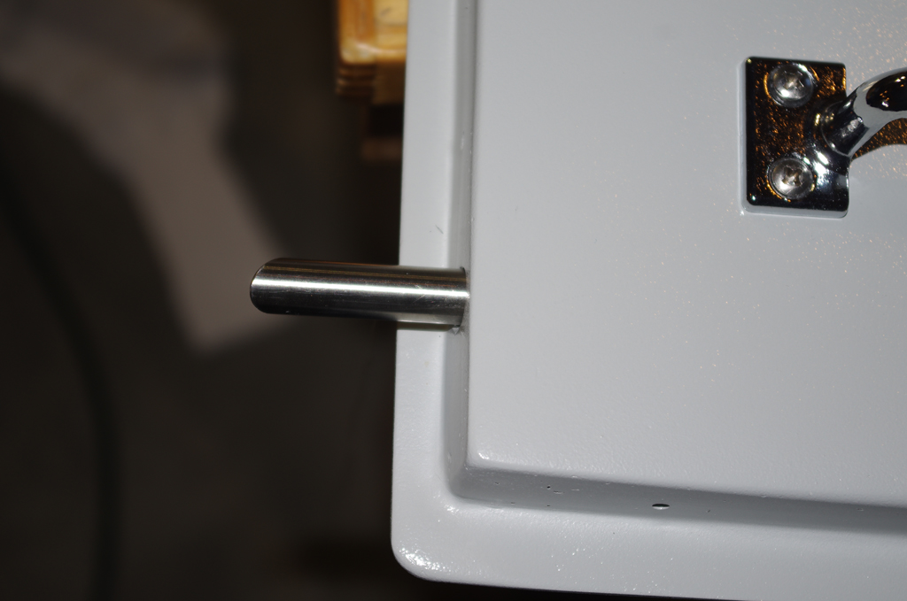
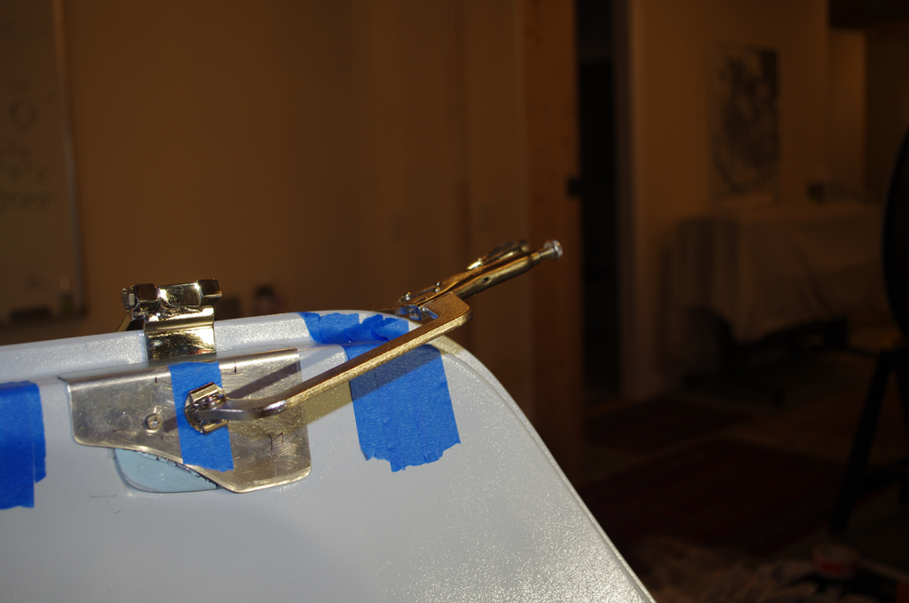
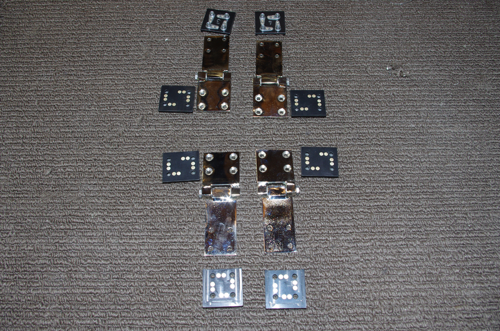
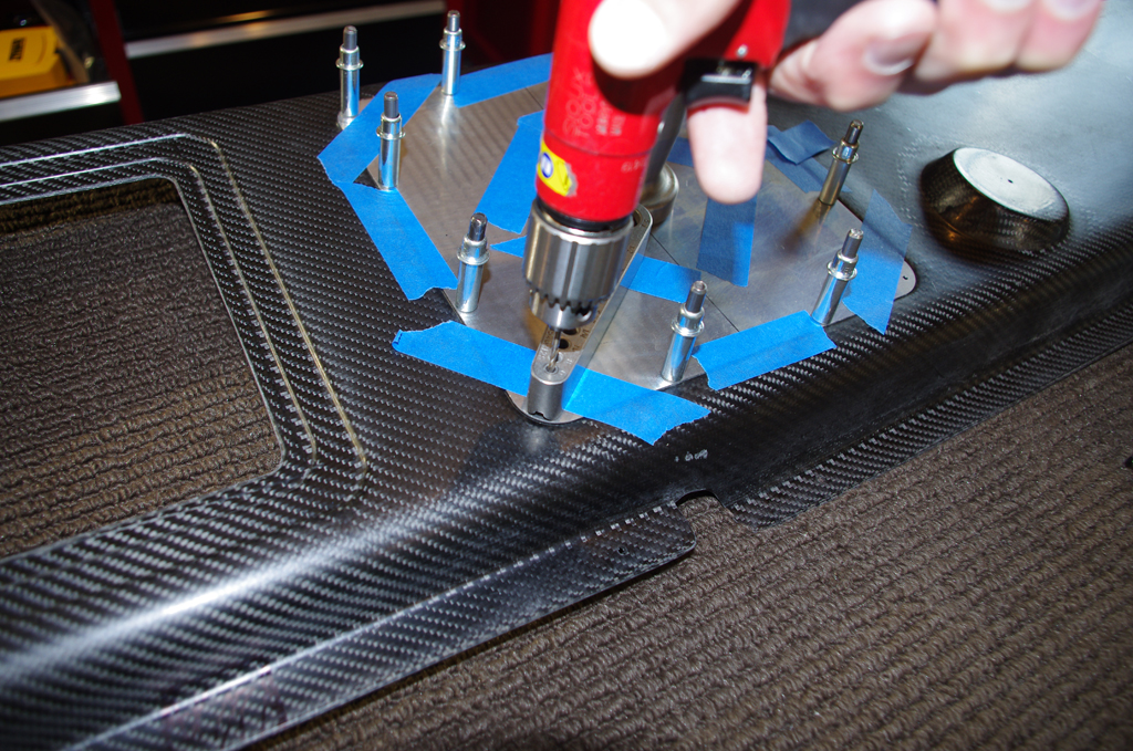
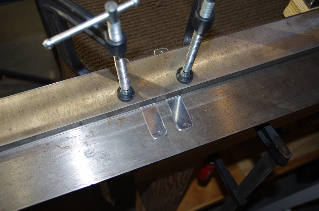
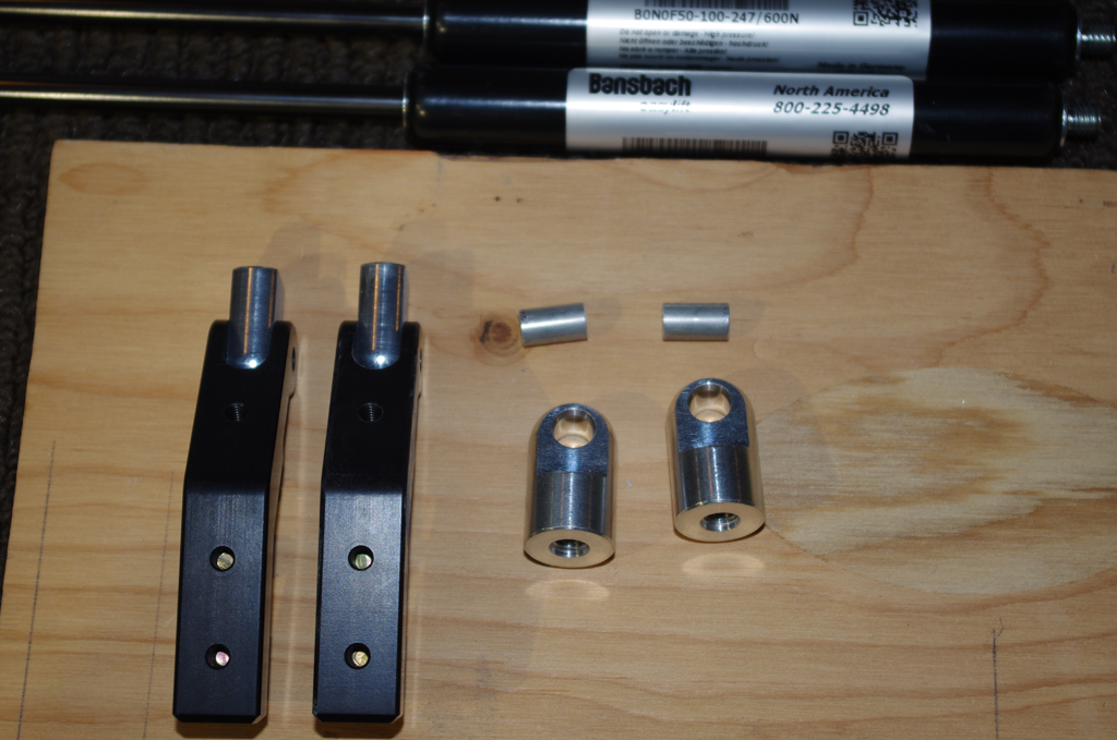
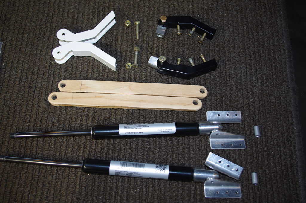
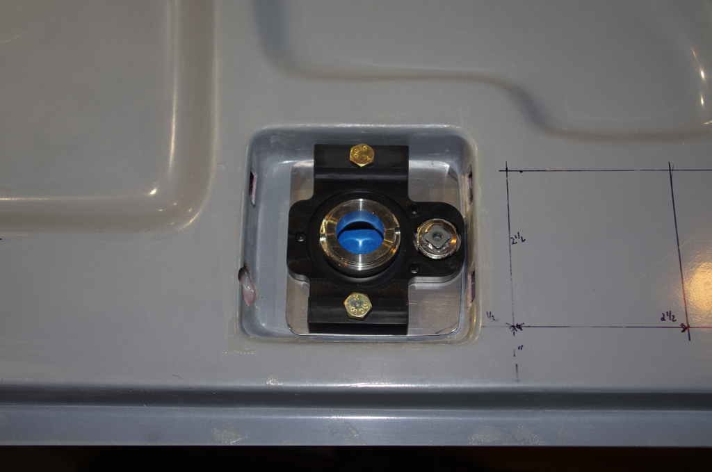
Attachment of the Aerosport low profile handles started with the base plate install (left). The handle with an enclosed return spring was then secured with a 1/8 x 3/4″ spring pin.  Later the center locking cam wheels of the PlaneAround latching system were as secured with spring pins. (not shown)


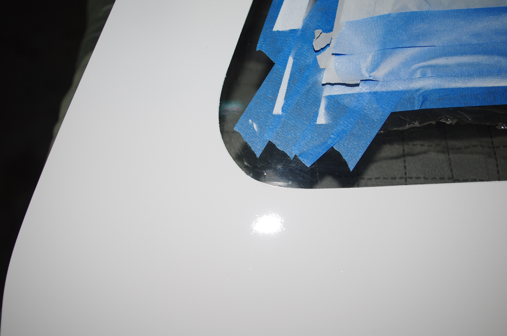
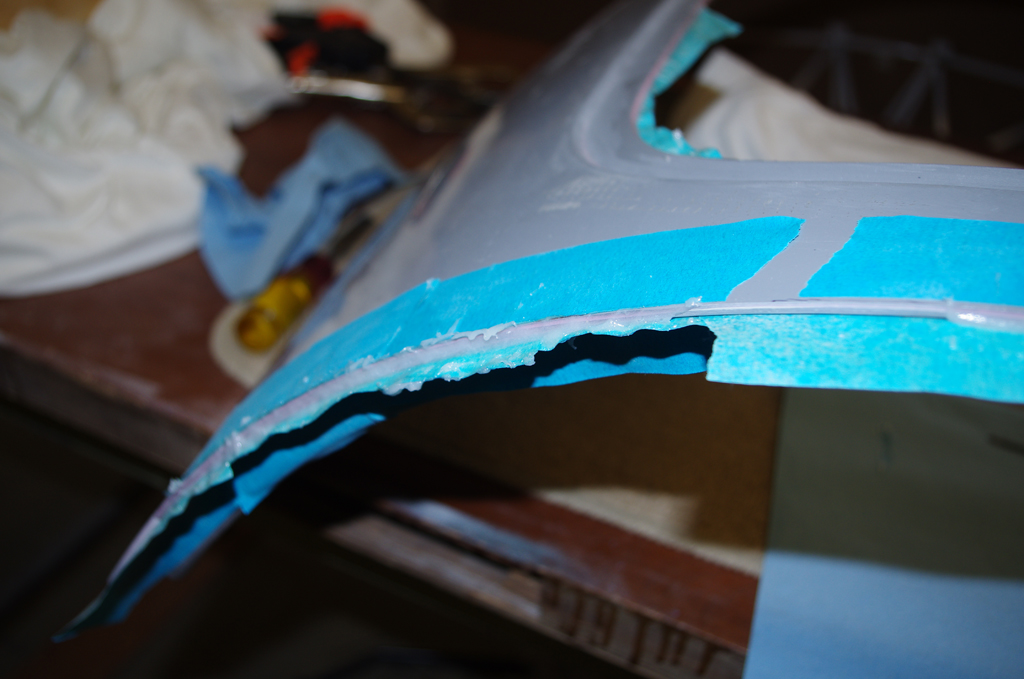
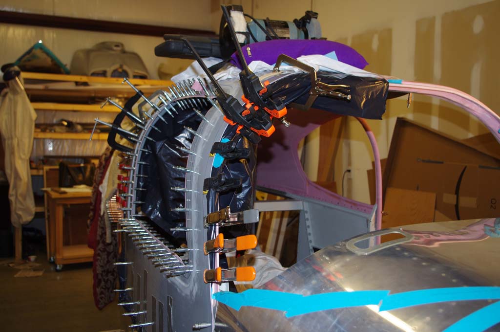
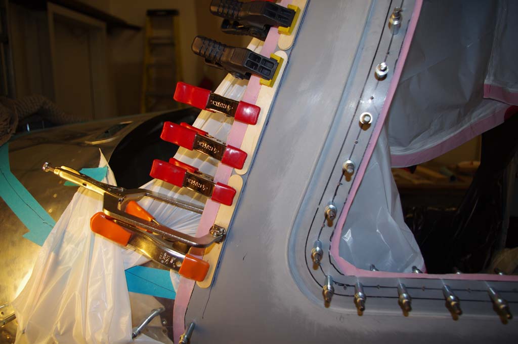
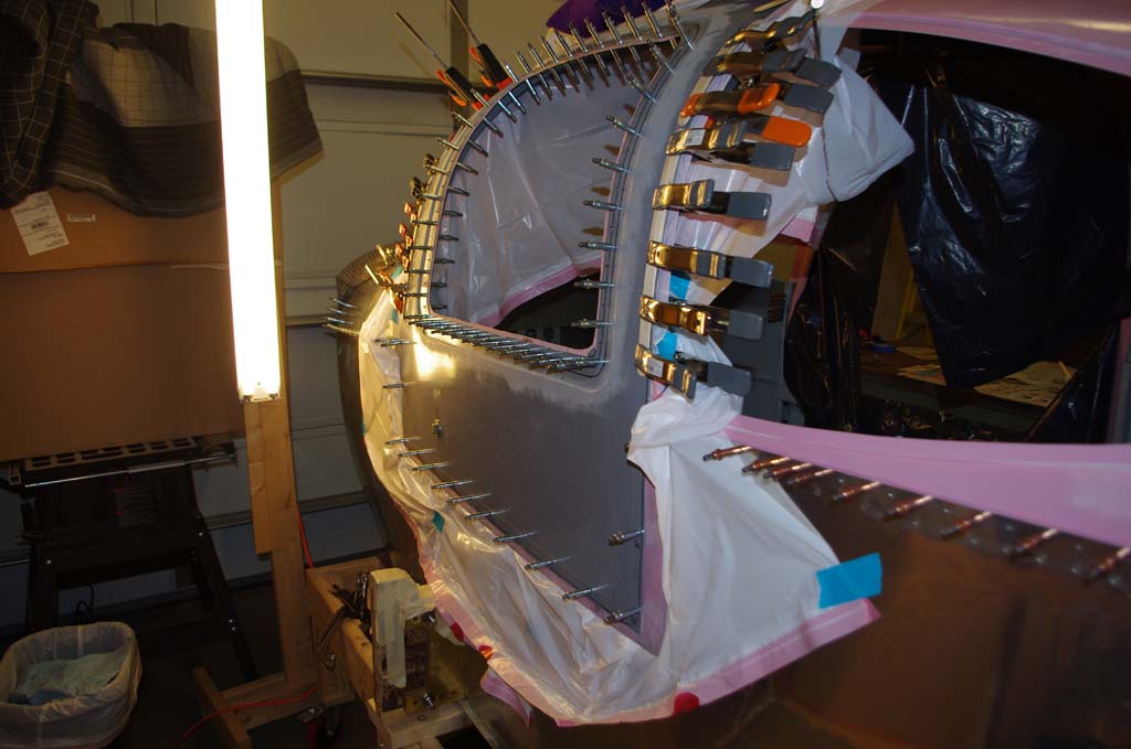
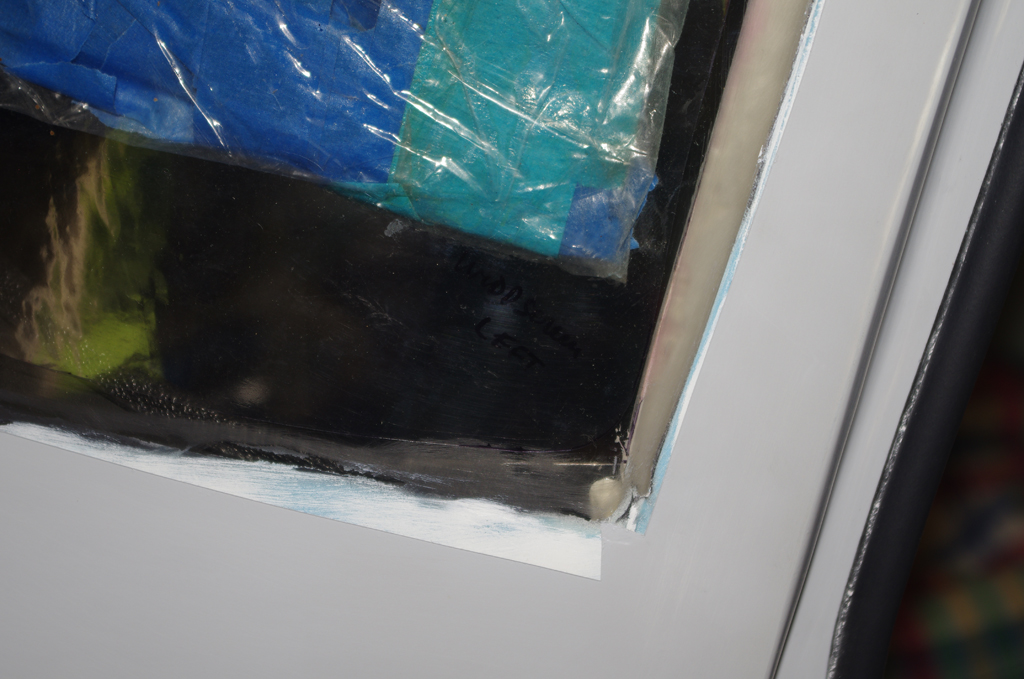
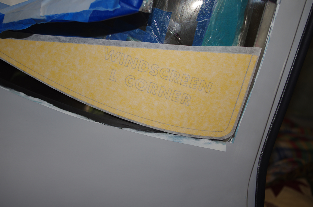
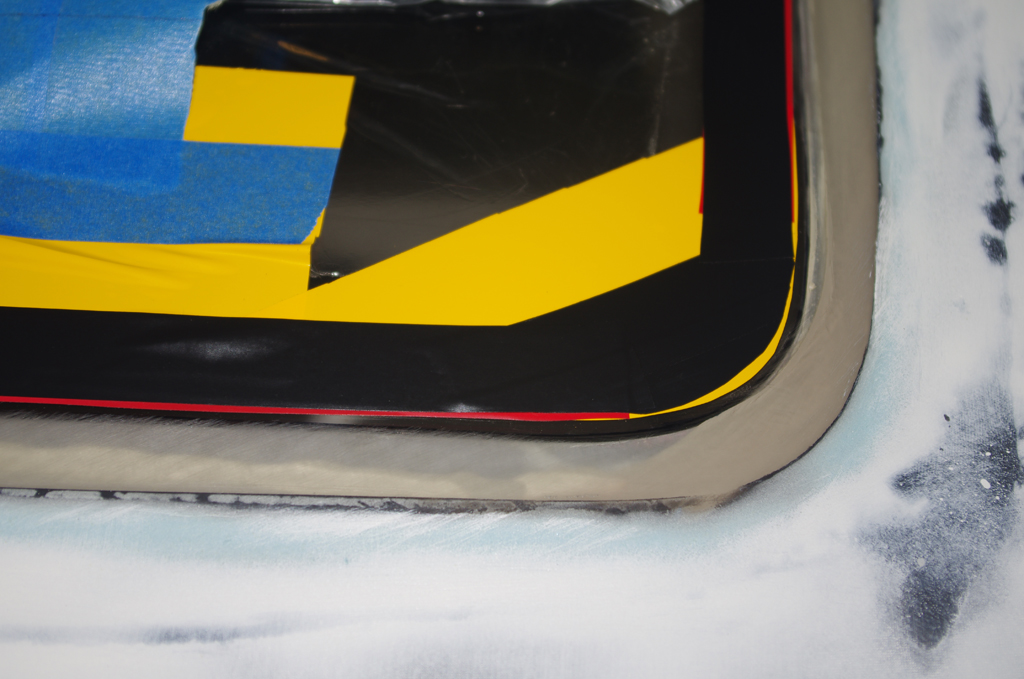
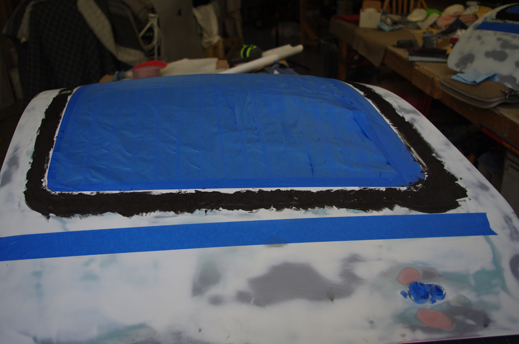
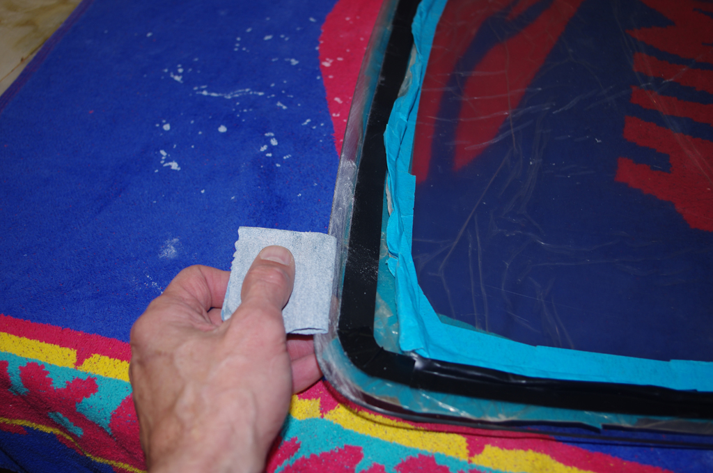
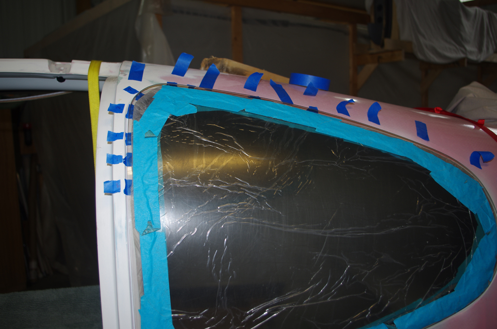
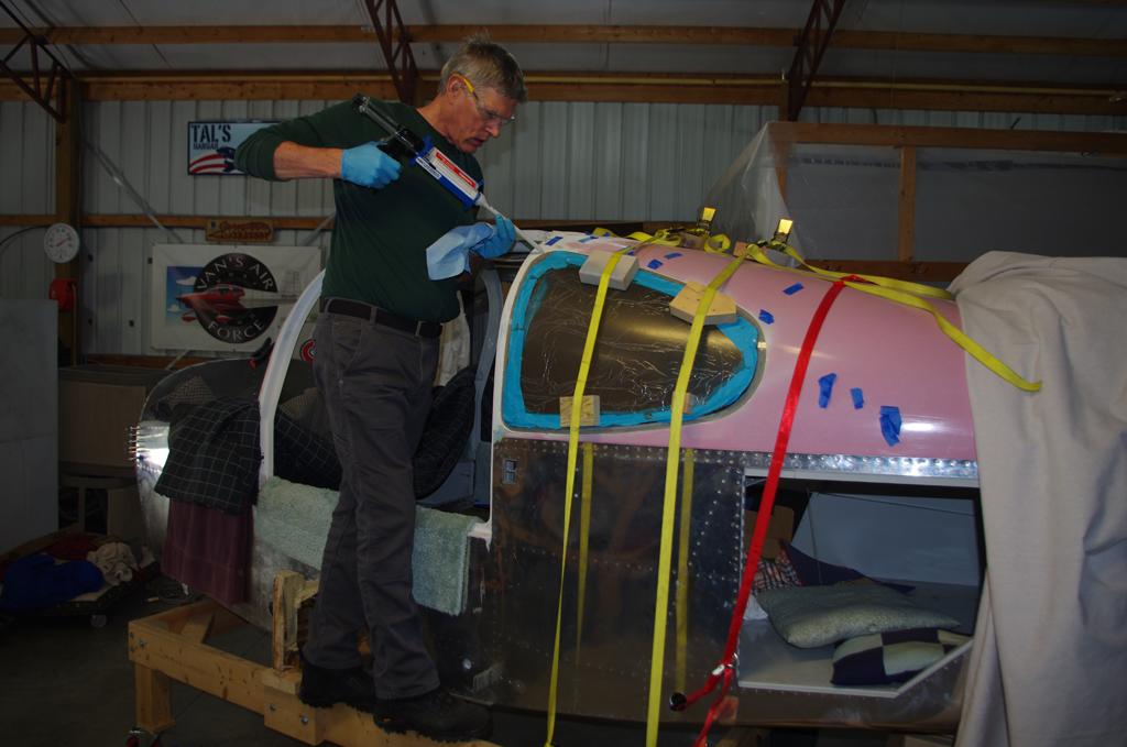
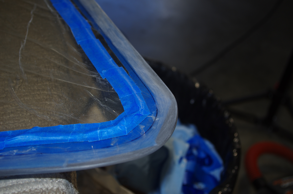
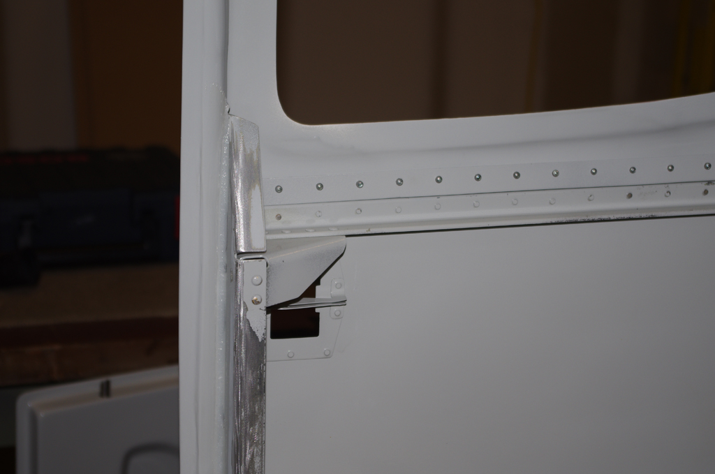
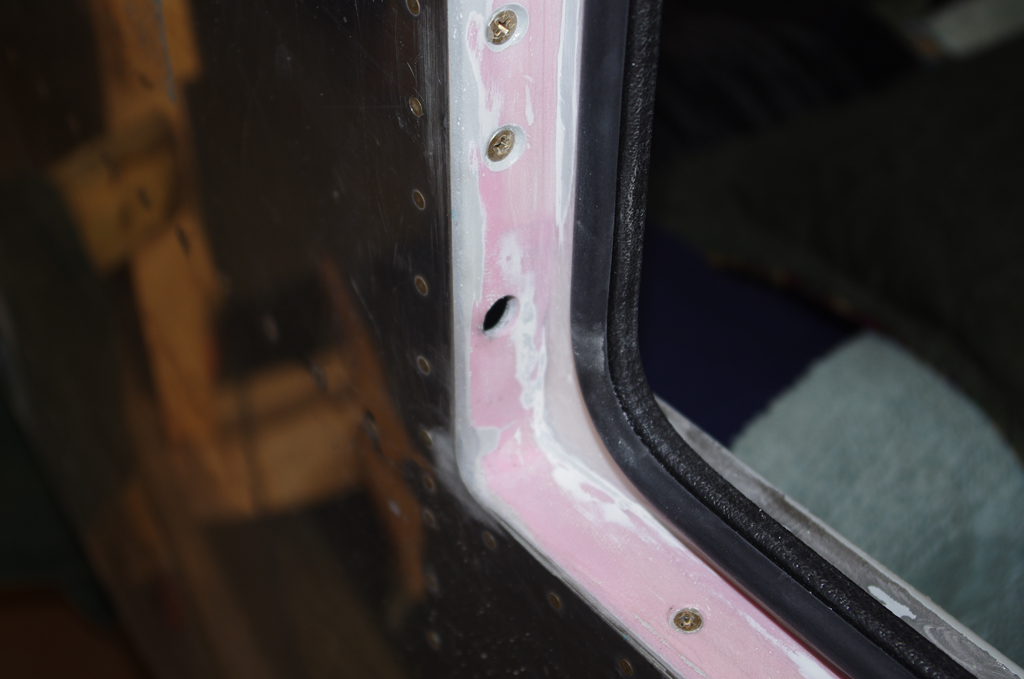
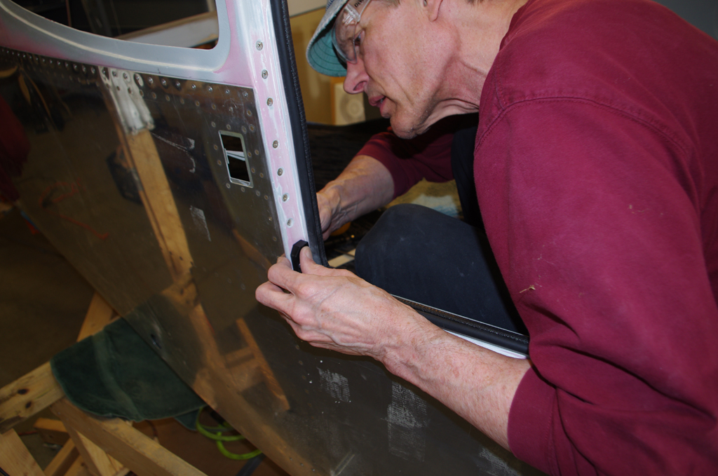
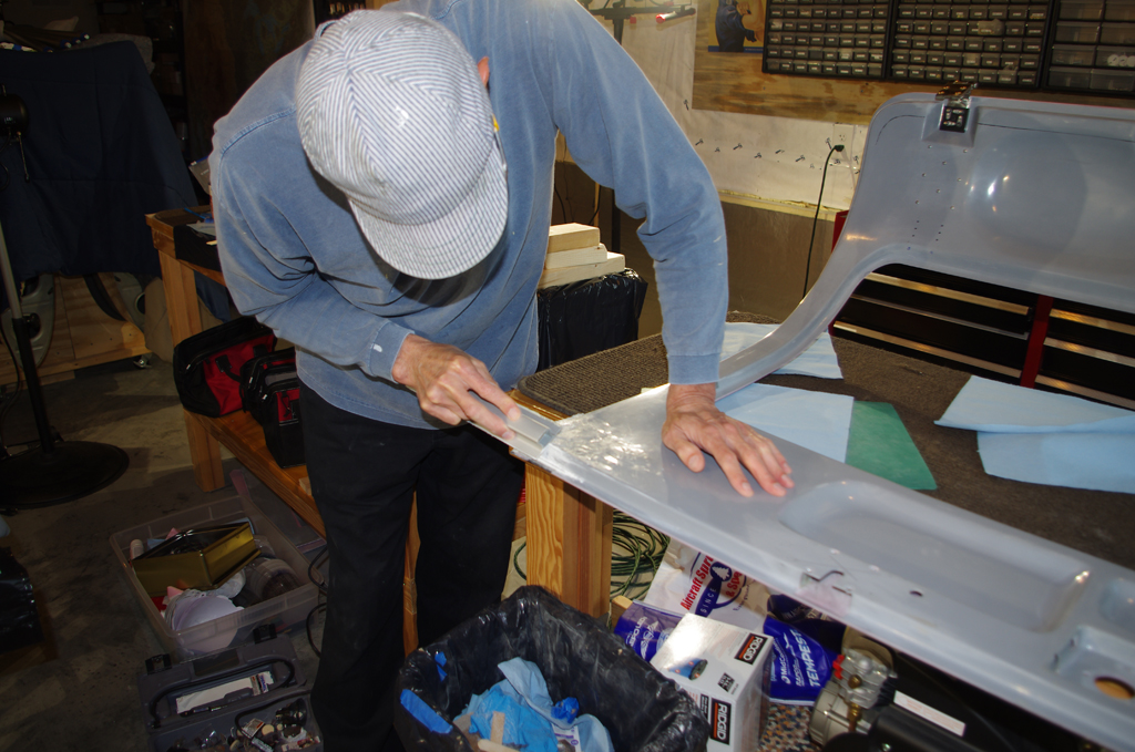
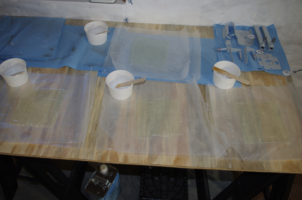
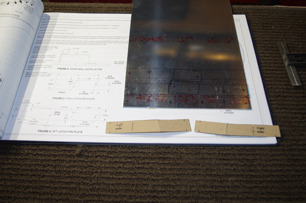
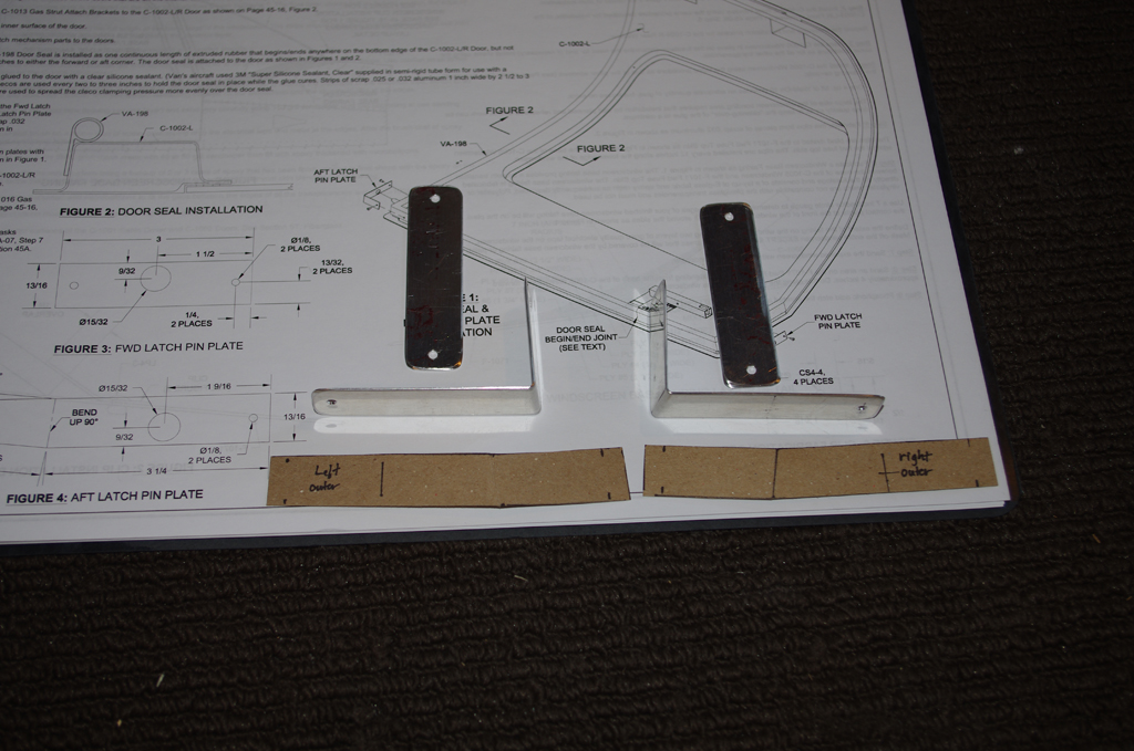
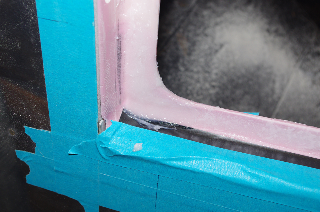
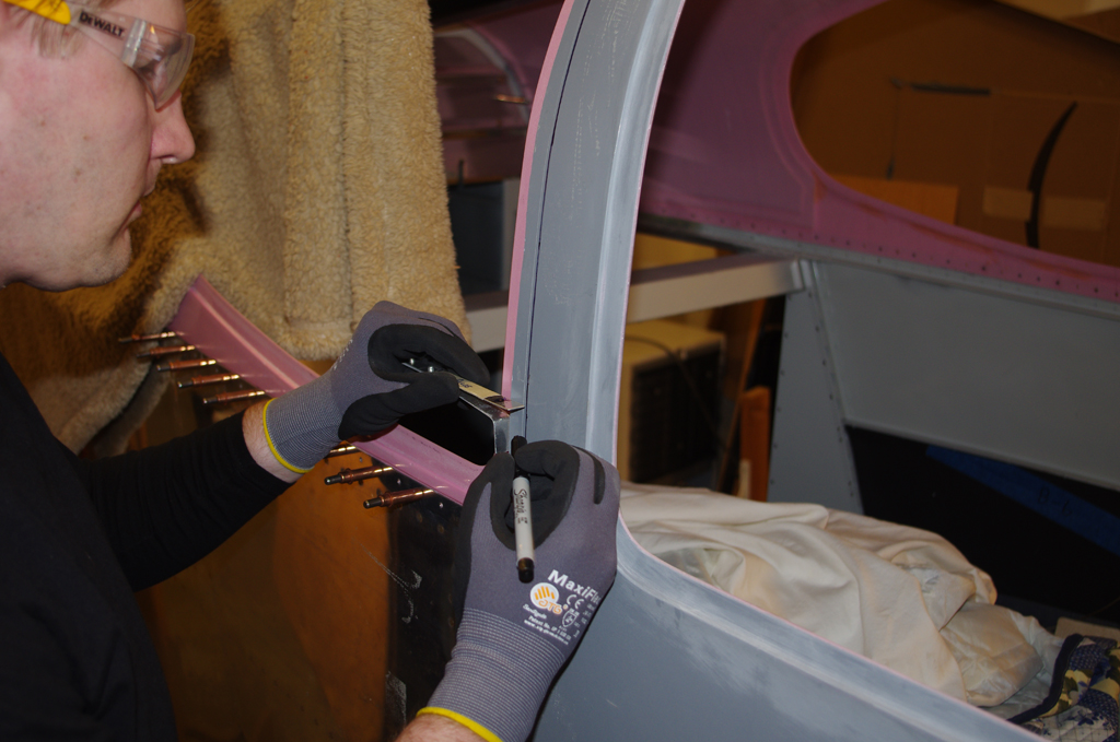
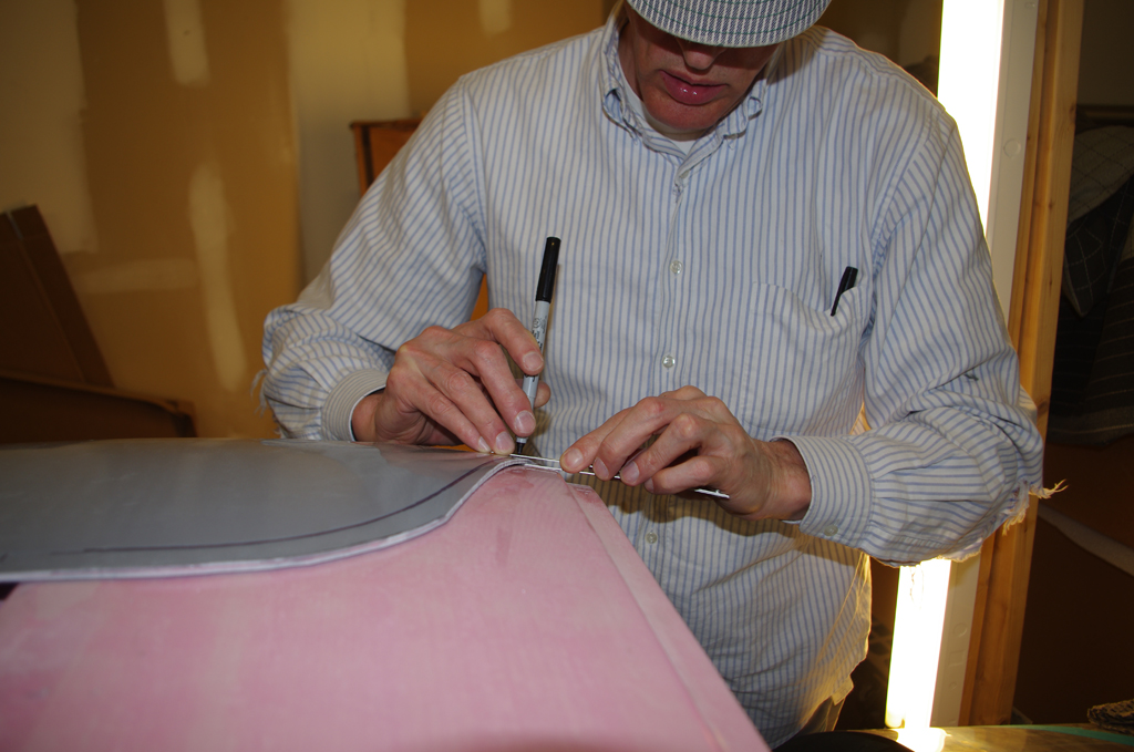
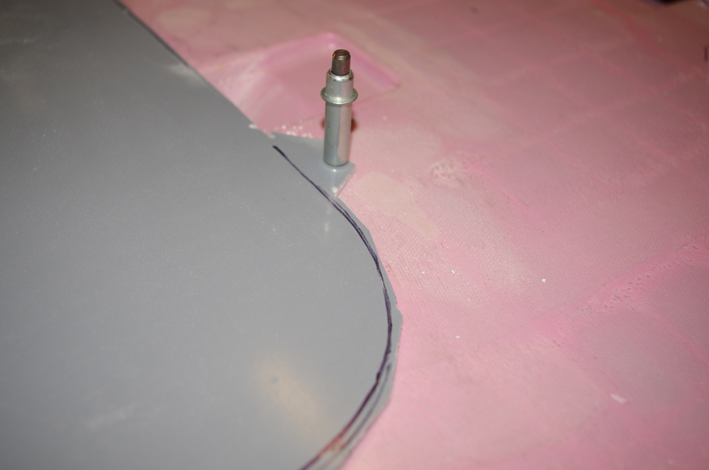
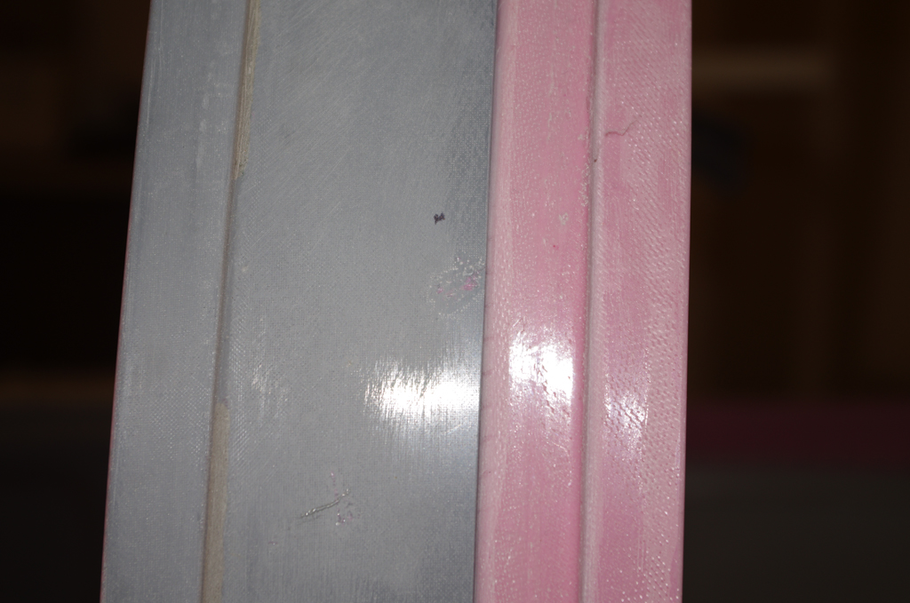
Here the edge tape from the door painting session was removed. The inner coverings were left attached in anticipation of the fuselage move on the highway from the shop to the airport.  The final door configuration is shown on the right.
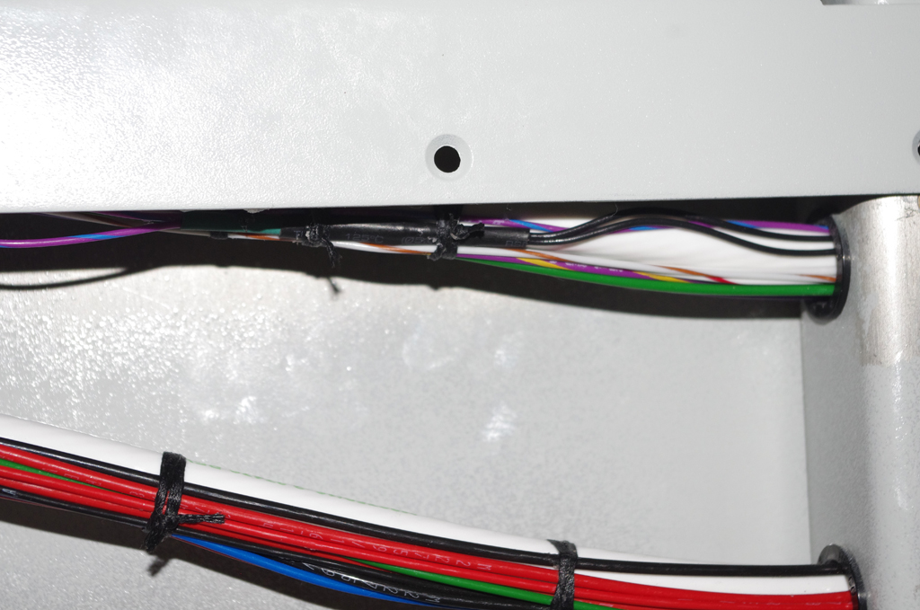
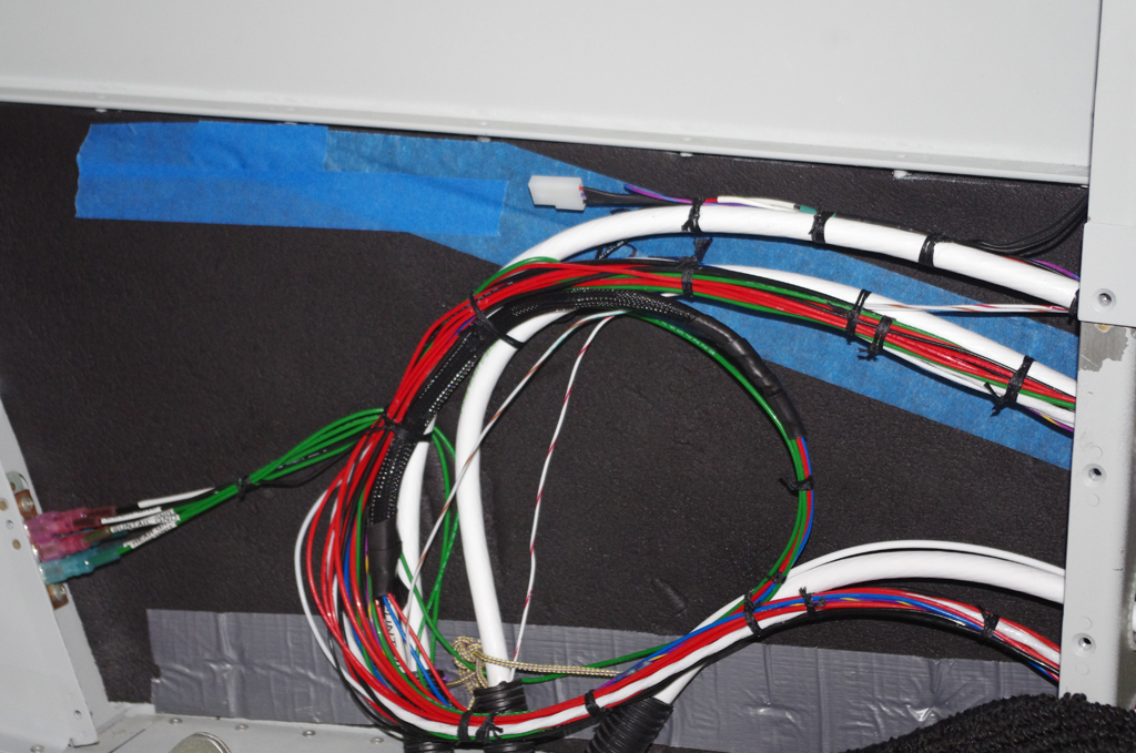
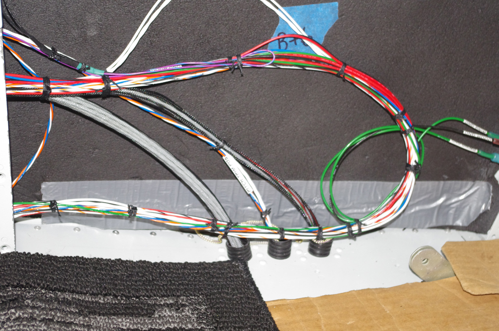
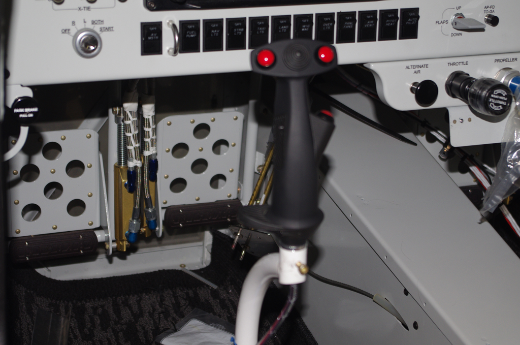


.

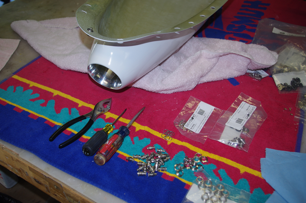
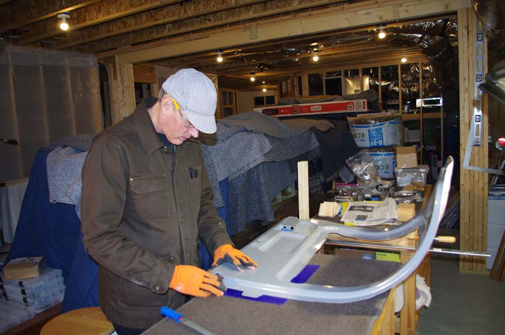
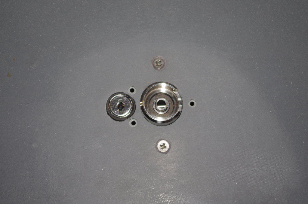
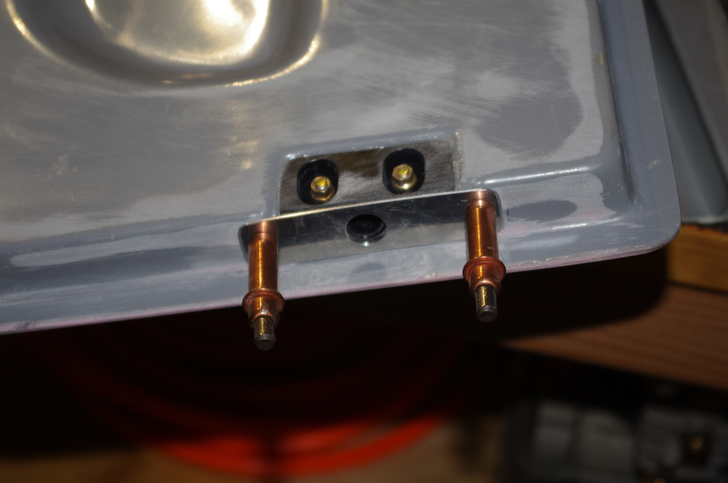
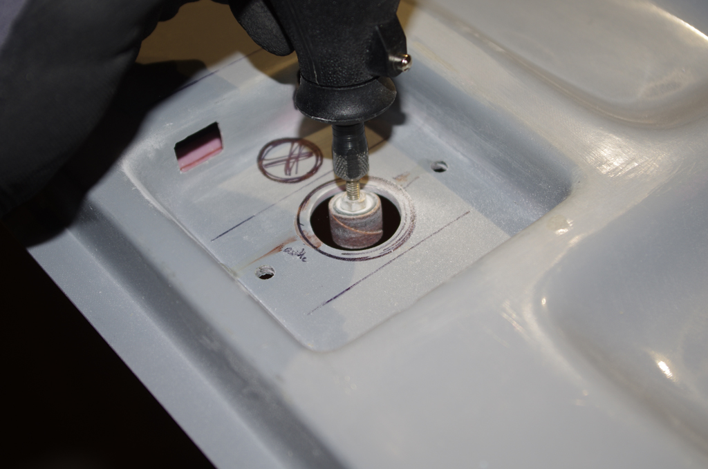
Adding Skybolt Camlocks to the lower cowl was a simple activity. In retrospect I would probably use that fastening system instead of piano hinges on all cowling parts. The cowl parts are MUCH easier to attach/remove with the Camlocks over inserting hinge pins in curved channels.


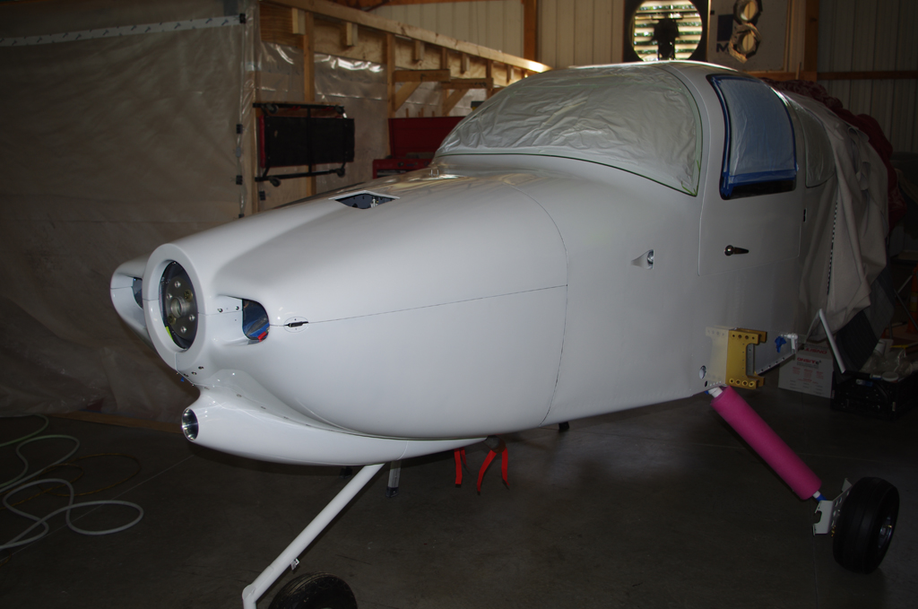
The Camlocks still needed depth adjustments on the cowl scoop before actual flight operations, but they were serviceable as-is for purposes of transporting the fuselage.

Transparencies and Misc

The templates for masking the window transparencies have finally arrived.  The Avery Dennision BriteLine+ vinyl sheets were custom cut by Moody Aerographics specifically for this purpose.  I originally intended to mask off each window with just one vinyl piece, but matching the template profile on the curved surfaces with the exposed sticky adhesive proved too difficult for an amateur installer.  Instead I chose just to use the corners which lay flat, with electrical tape filling in the straight or slightly curves intermediate sections.

The left photo shows the raw templates on the main roll.  Before applying to the windows, an outline of each corner was traced on acetyl sheets.  The reason for retaining this contour will be shown later…


The left lower windscreen corner was raw fit with epoxy resin and SuperFil before priming.  The corner template mask was laid into the corner with about 1/8″ – 1/4″ offset from the underlaying canopy frame.  This offset will present a clean edge visible from within the cockpit.


The smoothly cut template mask was covered with two layers of electrical tape.  Each tape layer provided an additional 0.0063″ height for when the AlumiLite black dyed and glass bead infused West Marine two part epoxy resin was applied to the edge gap.  The resin will then be sanded carefully from layer to layer to reach the final height of the template mask.


TAPING DETAILS

The same general taping process was then applied to doors and windows.  The raw template mask in the corner was connected to other corners with red electrical tape.  The bright colors for the final tape layer were used to enhance visibility while sanding.  Notice the curved black electrical tape second layer.  This shape was rough cut using the acetyl sheet contour described above. Cutting the electrical tape in this manner helps it stay flat, as compared with trying to bend the tape around a tight corner.


Additional black electrical tape was applied above the straight sections, followed by general masking and one more layer of vinyl tape roughly laid around the perimeter.


These photos show the before and after initial application of the dyed resin for the front left door.


These photos show the rear left window progressing from taped outline, dyed resin applied, initial rough sanding, and final edge sanding.


The last sanding step levels the lowest tape layer with the resin material.  Since this is only about .006″ thick, the care needed to not rub through to the Plexiglass window is extreme. It took quite some time to achieve this on the windscreen, doors and windows. The sanding outcome so far looks good, but application of the primer and paint will show whether the preparations were sufficient.


OIL DOOR LATCH BUTTONS

The issue of the push buttons for the oil door has finally been addressed.  A #30 hole was drilled into the Camlock latch plate, then taped for a #6 screw.  A mock-up of the final buttons (yet to be fabricated) are represented by the washers on the right.


The Delta drill press and a V-block were used to drill a 1/2″ steel bar with a center hole.  That hole was then taped for a #6 screw.  The taped post held a piece of 1/8″ aluminum flat bar for shaping.


The blank was hand filed and then sanded to exactly fit into each latch hole. The sides were slightly rounded to self-center the button when the latch springs back to the closed position.  The final buttons were polished with 2000 grit sandpaper and fastened with #6 stainless screws. They will probably will be left as-is and not be painted, but that decision will be made later.


MISCELLANEOUS

The original plans call for an AN3 bolt to hold the steps in their cradle.  I wanted a stronger connection, so the steps and the cradles were drilled and reemed to 1/4″ to hold thicker AN4 bolts. (NAS-


The door alarm reed switches were connected to the main electrical bundle via DSUB connectors.  They are held together with heat shrink, then laced into place.


The main wiring bundles on left and right sides under the rear seat panels were laced together.  In retrospect I would probably rearrange some of the wire runs for a cleaner look, but the final result is secure and will be serviceable as needed for future maintenance.


The control sticks were cut to length to provide the maximum height without touching the instrument panel or switches.


Transparencies and Miscellaneous

The Lexan/Plexiglass transparencies used for the rear and door windows were bonded with Lord 7475A/D two-part epoxy adhesive.  These parts were trimmed to size and smooth sanded in prior posts.

Electrical tape provided protection on the rear windows during roughing the inner surface with 120 grit sandpaper to enhance adhesion.  Then the window frames were taped so excess adhesive could be easily removed.


Shims in the form of AN960-10 and AN960-10L washers were placed to bring the window surface to level to -.010 inch of the canopy. This helps with the physical holding of the window, plus will allow for later blending with filler to a smooth transition.


The bonding process was a bit scary – only one shot to get it right.  The reason is the Lord adhesive cures very quickly and is extremely difficult to remove after it sets. Fortunately the rear windows turned out fine.


The same method described above was used on the door windows.  Straps and clamps hold the windows tight to the frame while the adhesive cures.


GMU MOUNT BRACKET

Previously a mounting bracket for the Garmin GMU 22 magnetometer was fabricated for placement in the mid-tail section. The angle of the bracket should be as close to zero degrees level with the fuselage waterline during flight as possible.  It was determined with a digital protractor that the bracket needed to be adjusted about 1.8 degrees down to meet this requirement.

The bracket was constructed so that brass screws adjust the tilt angle of the magnetometer platform to the flight waterline.  More on that adjustment in a later post. Here the GMU bracket is positioned along the plane centerline


The GMU bracket seen from above and below after priming from the hole drilling.  Note the use of brass screws and stop nuts.  According to vendor specifications, any magnetic components should be at least 2-3 feet from the magnetometer. The location of the bracket in the tail should achieve this goal.


These pictures are the final fit of the GMU bracket to the custom platform.


Canopy, Doors, and Custom Parts

Work has continued on plane parts, though the frequency of my posts has diminished since the beginning of the year.  Here is a quick catch-up of recent activities.

The fuselage sill is filled with two-part resin/colloidal silica mixture just prior to dropping the canopy into place.


The lower retaining screws are locked into position while the resin cures.  Next the canopy and mid-skins are pop riveted together along both sides.  These two actions permanently attach the canopy to the fuselage.


Here are exterior and interior views of where the canopy and mid-skin meet. Overall a nice result.


DOOR HINGE PIN BLOCKS

The PlaneAround center cam gear block is located under the gear mechanism and then drilled/screwed in tightly.


Next the door pins are replaced with custom turned 5/16″ bolts to indicate the exact locations of the bulkhead through-holes.  The right photo shows the resulting latch pin location.


Finally the outer pin blocks are positioned to force the door down and in when the door lever is activated. Right now the fit is very snug, but I expect this will loosen a bit over time.  One this is for sure with this configuration, those doors will not be coming off the airplane in flight!


Baggage Door Hinges

I was not happy with fit or configuration of the original baggage door, so off came the larger hinges.  These were replaced with smaller hinges, and pins moved to a middle insertion point.  This allowed the relationship between the door, hinge and outer skin surface to be flush, as compared to having the hinges sticking out to allow pin insertion.


Custom Parts

Moving heavy objects around in the basement shop will be helped with a few custom-made skates.  These are made from 2×4 steel beams, 5/8″ drill rod at 10-2RS sealed ball bearings.  The plans are from the internet with no welding required, just proper alignment in the drill press. Eric will make 3D printed end caps to hold the skate axles in place.

Cabin Doors, Custom Parts (2)

Installation of final door hardware and fabrication of custom hinge pocket covers were the topics for a few weeks.

Door handle, gas strut attach bracket


Aerosport low profile latch mechanism, interior and exterior views


adding magnets to latch pins, interim rod assembly, and final pin actuation


door hinges attached to door, preparations underway for fabricating the custom door pocket covers


fiberglass formed to exact pocket dimensions, cover plate clamped in place for adhesion to molded piece


initial sanding of canopy interior, initial installation of wire runs in forward canopy channel with E6000 adhesive


application of fiberglass over wire runs, which are actually 3/8″ air hose line.  build-up of inner door hinge pockets for even base for Airward nutplate pieces


forward and center canopy sections filled with Superfil and smoothed in preparation for bonding in overhead console


custom covers for the overhead console where the reinforcement bar comes up from the dashboard

Cabin Doors, Custom Parts

This summary covers a long period after Airventure, and prior to Labor Day.

The hinges finally can back after being chomed.  The results are good, and primarily based on the degree of preparation sanding I put into them beforehand.  Hinge pins are cut to length from stainless steel AN3-21 bolts.


Hinge pin locations are covered with resin, then sanded smooth.


The sand, resin, repeat process took a long time to get the surfaces just right.


Once the doors were ready, a batch of alodined parts was also prepared to prime/paint at the same time.


Tal’s paint booth was used to spray the doors and the parts.


HINGE COVERS

After painting the doors a build of custom hinge covers is needed to provide a good seal to the McMaster weatherstrip. Some modeling clay was used to partially fill the hinge pockets.


Then a few sheets of fiberglass were prepared, then pressed into position while still flexible.  Fitting and flush mounting remain after the sheets dry.


OVERHEAD CONSOLE / GPS ANTENNA MOUNT

I would like to have the GPS antenna for the Garmin GTN650 located under the canopy. However, the antenna attachment is too deep to fit in the gap between the canopy and the overhead console.  A custom cover was procured via 3D printing from AeorSport Products.


A mounting platform for the antenna itself was made from spare aluminum angle and sheets.


The platform is hinged, so exact angle with airplane centerline and flight angle can be achieved.


The hole for the custom cover is fabricated in the rear access panel.


Here is the final test fit showing the configuration of the cover, mounting bracket and antenna. Once the console is bonded to the canopy, the bracket can be permanently installed.

Cabin Doors (5) – Latch Pin Guides

After preparing the latch pockets, now the latch pin guides.  These are originally intended to secure the Van’s weatherstripping. I want to add them as a framework for some resin around the pin blocks.  The idea here is fully enclose the pin blocks in order to provide a smooth, sealed surface for the McMaster seals.  Yes – the pin blocks will be permanently encased in the door, but there are ways to install or remove the pins without dismounting the pin blocks. (more on that topic will appear in later posts)

First steps are layout the pin guides on a sheet of .040″ aluminum.  The designated 6.8degree angle supposedly compensates for the angled door frames. A protractor is used to get the angle close (only has degree increments).


Stiff construction paper prototypes were cut prior to making any metal parts.  I wanted to check the effect of the angles on the corners.  Close enough for some hand shaping to be effective.


The roughed out pin guides are then inserted in Tal’s sheet metal bender and formed per plan instructions.


Here are the pin guides prior to fitting on the doors. Actual fitting required a bit of material removal. In retrospect I would first fit the pin guide hole from a slightly larger blank template, then shape down the attachment tabs to fit to the door geometry.


Here are the raw and final fits on the passenger door aft guide.  Getting the pin hole aligned properly took time with hand filing.  The final gaps are good.


Here is a passenger door forward guide. Much easier since this is a straight piece.  Now everything is ready for alodine/prime and covering the pin block with resin.

Cabin Doors (4)

The slow process of applying filler and sanding on the doors, frames and canopy finally has an end in sight. Much of the time was preparing the door frame J-channel for accepting the McMaster-Carr weatherstrip molding.  My intention was leave as much of the original canopy material in place as possible, just relieve enough for a good fit between the final lip and the door inner shell. In most cases this was sufficient, but on the lower door halves the default gap was wider than could be bridged by the weatherstrip.  Here I opted to apply fiberglass/resin to build up the outer edges, then sand smooth and fit for a much better gap.

These photos show the lower left and right corners of the passenger door.  This was the hardest area to build up.  The default J-channel was very irregular, varied in thickness and sanding in the corners was difficult.


After getting the doors to an intermediate fit, off came the doors and hinges.  The intention is to send out the hinges for chrome.  However, the steel finish as provided from Van’s is pitted or marred with milling marks.  The portions which will be most visible after installation were hand sanded and polished. Hopefully this preparation step will lead to a better final look in chrome.


Another set of fabricated items for the doors are hinge spacers for the Bansbach gas-struts, and bracket locating bars made from 3/8″ plywood.  These bars will be used to properly set the distance from the AirWard strut brackets to the hinges on the inner door panel.


LATCH MECHANISMS

The exterior door handles provided by Van’s extend quite far from the door surface.  After long deliberation I opted for the AeroSport low-profile handles.  This requires modification of the latch pockets, but now is the perfect time as the doors are not finished anyway.

This photo shows a thin metal striker plate will be fabricated to accept the modified Delrin block to hold the standard latch gear and accommodates an integrated lock mechanism. This requires boring out a larger hole for the handle lever and a pass-through for the lock body.


The right photo shows the passenger door being modified for the larger lever body and lock hole.


After the modification, the fiberglass around the lock is quit thin.  Now I see why a plate of reinforcing steel is needed.


The lock does fit well, though maybe a lock with a shorter body would be better.  Why – the Phillips screw holding the locking lever extends above the surface of the door interior.  This would make fabricating a vanity or cover plate difficult.


AILERON PUSHRODS

My first attempts at making the aileron pushrods did not turn out very well.  So I reordered the parts and tried again…

This picture of the initial rods show how the rivet hole is chowdered badly from the drill press.  The rod was not secured properly and moved drastically during the process. My bad.  The rod was being held in a drill vise with the end sticking out, no support provided on the outer end to take the pressure and keep the rod from bending.


At least two lessons were learned from the previous exercise:  measure twice…  and make sure the part is properly secured when drilling.  In this photo shows measuring the 48″ rod to ensure there is sufficient room at the end to fit into a precision V-block on both sides of the drill location.


After spot drilling (lesson 3 for small diameter rods, keeps the drill from wandering on initial contact) the separate inner holes are drilled.  Note the V-blocks on each side.  The rod was then cut in half and the two pushrods were adjusted by hand filing to 21 – 11/32″ length.


The drill results are very good.  The insides need to be primed, then all the through rivets will be inserted.  The right photo shows a end of each rod with one rivet.  Nice tight fit and no wiggle in the threaded ends.


Cabin Doors (3)

Sanding and fitting door to the canopy have been my main activities over the past few weeks. The work has been tedious, but I prefer taking off smaller increments to slowly get the shape down to cabin contours than accidentally removing too much with a power tool.

First up was finish bonding the passenger side door together around the windows and exterior edges.  That done, next mount the rough door on the canopy opening.  The right picture shows marking a rough  cutout line using a special jig tool made by Tal.  Worked great!


Here the custom tool with a very fine point Sharpie marks the upper door edges. The Sharpie line roughly equals the scribe line in the fiberglass outer shell, but differs enough to require carefully measuring all around.  As usual, the fiberglass mould used for the canopy is just an approximation, nothing precise at all.


Left picture is a rough trim on the upper door near the hinge.  Notice the single alignment tab still the outer edge. The right photo shows a later fit after many, many hours of hand sanding.  The last bit of shaping used a folded sheet of sandpaper moved back and forth sandwiched between the door and the canopy frame.  Makes for a nice fit.


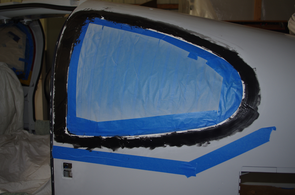
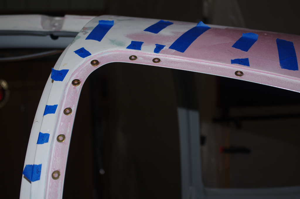
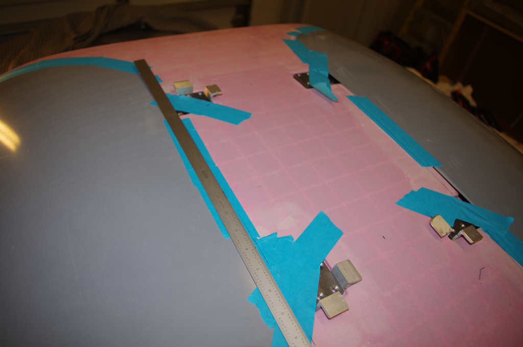
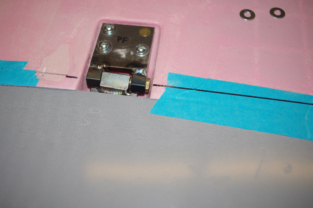
Here is a closeup of the door against the cabin center column.  The next step was tape the roughed in door into position, get ready to install hinges.


A two foot straightedge is used to mark the centerlines of the hinges.  If the hinges are not aligned just right, they will bind when the door is opened.


Okay. Drill the canopy hinge first, and install four temporary #10 screws.


Open the door for the first time and check the fit.  The edge distances are uniform and the hinge action seems smooth although only two screws hold the door in place.


The remaining door hinge holes are then drilled and screwed.  The next major focus of the door build will be contour the canopy gutter edges to the proper geometry for weatherstrip moulding.


Some touch up of small edge gaps from the previous bonding process remain before moving on.


Cabin Doors (2)

Over the past few weeks, many distractions for home improvements have gotten in the way of progress on the plane.  However, a recent visit from Rich has helped put wind back in the sails.  My approach was to finish as much work on the latches, gear boxes, pin blocks and other accessories prior to bonding the inner and outer shells together.  Made for much easier access to some tight areas.

Here the Delrin pin blocks from PlaneAround are being shaped with a vixen file to match the corresponding door pockets.


Next action is bond on fiberglass reinforcement squares from the PlaneAround kit around the center gear box.  A cover plate was fabricated to cover the cam shaft slot opening on the inner door panel.  This is not required for structural reasons, but should add a finished look.


The default Van’s pins are bent, measured and cut in preparation for adding stainless steel and machined PlaneAround pin tips.


The pins are cut to approximate length, but must be hand filed for the machined pin face to be oriented correctly.  When done right, the pins should pull the door down and in when engaged.  The pin is tapped for a 3/8-24 bolt which is tapered slightly for easy insertion.


Rich confirmed proper geometries and alignment of the latch parts, then began preparing to apply foam for sound dampening.


The last step before bonding is shave the foam flush with the inner surface.  The shells edges were sanded and test fit to ensure no excess foam interfered with smooth surface contact.


BONDING PROCESS (over a few days duration) ================

Over at the rented shop, the right side is covered with plastic to prevent extra adhesive from squeezing out the edges onto the canopy.  Then West System epoxy is mixed together.  A batch of ‘neat’ (no fillers) with three pumps resin and three pumps hardener was prepared to wet both shell surfaces.


Here the elbow pocket is covered wet before application of a 5 x 9 inch piece of Permabond (triple layer fiberglass mat).  The mat was thoroughly soaked in neat adhesive.


This photo shows wetting the cranial cavity on the inner shell.  This area was treated with the same Permabond as for the elbow pocket. After this operation, I had an issue with the bonding material used for the right door outer edges (more on that later)…


When done properly bonding the outer edge used three separate batches of three pumps each of resin/adhesive first mixed together, then stiffened with six spoonfuls of West 406 (colloidal silica).  The consistency turned out similar to peanut butter.  The final adhesive mixture was spread about 1/16″ evenly on each surface before mating together.


Clecoes hold the lower section to the fuselage through witness holes.  Clamps have been applied to the sides along the door channels.  Sandbags about 25 pounds each and other extra weights hold the top section in place.


Rich had the good idea of using kraft sticks to distribute the clamping pressure along the door edges.  A firm, uniform clamping force is desired.  Too much pressure causes the adhesive to be forcefully ejected from the bonding location – effectively ‘starving’ the joint and causing a weaker bond.


Here is photo from a different day of the left door clamped onto the canopy to cure.  The recommendation is allow 24 to 48 hours to harden before removing.  This lets the door permanently shape to the contour of the canopy.


The bonded door shells are very tight, no fear of delamination here! Now begins the process of trimming the shells to final dimensions.  First the window frames, then the door edges to match the frame openings.


Confession time:  On the right door I mistakenly used sealant instead of fiberglass adhesive on the outer edges. Fortunately I was able to completely remove the sealant before proper application of the epoxy adhesive.  Overall the final outcome for both doors was very good and structural integrity is preserved.


Post Navigation