While waiting for replacement parts for the flap control rods, I began working on the cabin doors over the holidays. My intention is prep, align, fit, and sand as many of the door latch parts as possible before bonding the two shells together. This should make the incorporation of a PlaneAround NEW180 cam door system much easier. This approach does require a sequence deviation from the original Van’s plans.

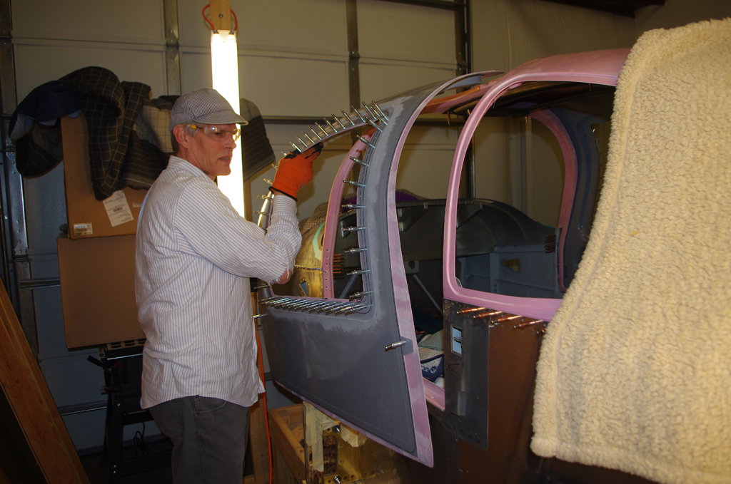
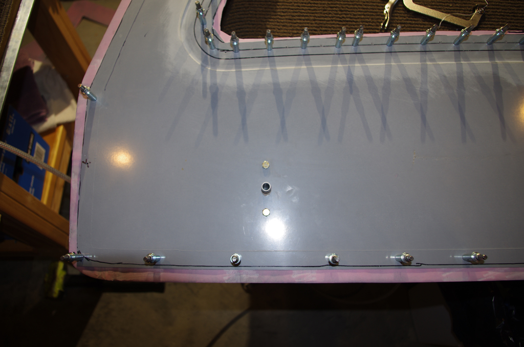
 First step is scribe lines on the inside of the window frames. The 3/4″ line will eventually become the edge behind the plexiglass windows. The other lines are for rough removal and setting temporary clecoes. The right photo show a few clecoes already installed along the bottom edge. I started here because the original witness holes are here and should provide excellent alignment between the shells.
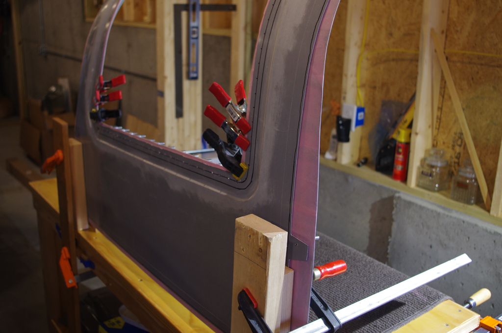
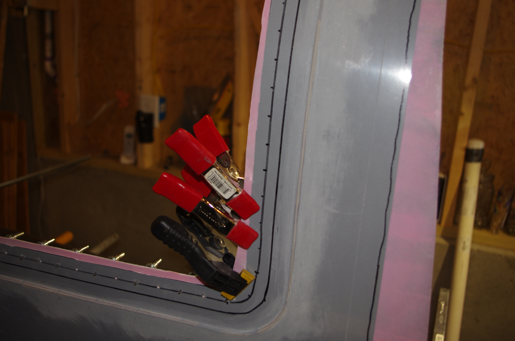 Next is fasten upright on the workbench and clamp inside the window frames. This should press the shells together and progressively flatten moving upwards for clecoe holes. Drill, clecoe, reset clamps, repeat until the inner frame is solidly fastened together.
 Clecoes are now installed at the windows. The entire door frames is then rough fit to the fuselage via the outer witness holes.
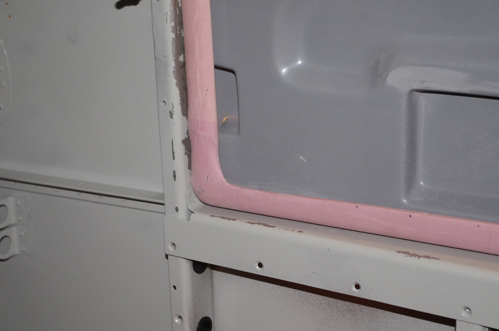
 Gaps to the fuselage are acceptable at this stage. They should become tighter as the door edges are trimmed.

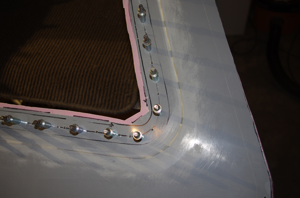
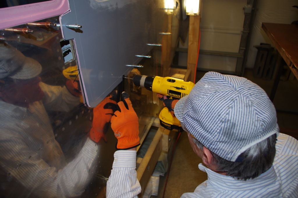 A 3/32″ hole finder is used to align open rivet locations in the fuselage with edges of the door shells. Holes are drilled, then clecoes inserted. Without the hole finder, this process would be nearly impossible to perform accurately via scribe lines!

 The rough fit process is completed with good results.
LATCH MECHANISMS
Now the doors are clecoed together, work on the original Van’s latch mechanism can begin.

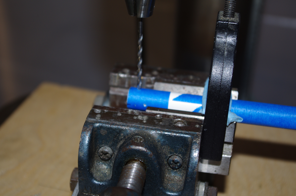
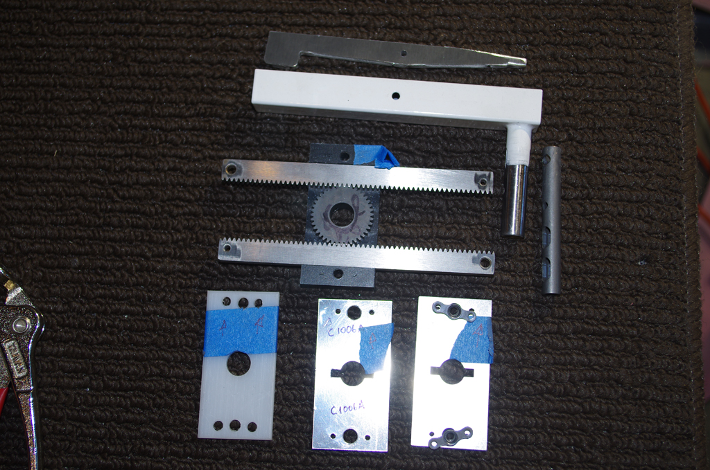 As usual, the parts are laid out before processing. Following the original plans, the C-RACK 10 was cut to Van’s specifications only to find the lengths need to be different for the PlaneAround kit. Oh well, another opportunity to order replacement parts.

 In the meantime, the latches are positioned in the middle of the corresponding door pocket both vertically and horizontally. Here are the final drill holes shown inside and out.
CAM GEARS / BACKERS
Having the door shells apart greatly facilitates working on the cam gear installation. One item of concern is the lack of reinforcement around the gear block. Access to the inside surfaces allows for creating a custom solution.

 This plate made from spare .040″ aluminum sheet is match drilled for the gear block, plus will have #6 nutplates installed for a vanity cover. These alterations should provide increased strength together with the fiberglass reinforcement blocks from PlaneAround.
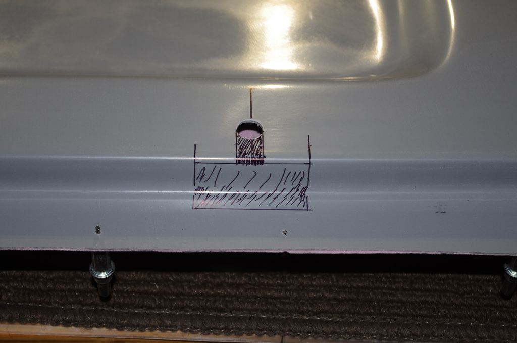
 This backer is for the gas strut attachment at the door (a standard Van’s feature).
PIN BLOCKS
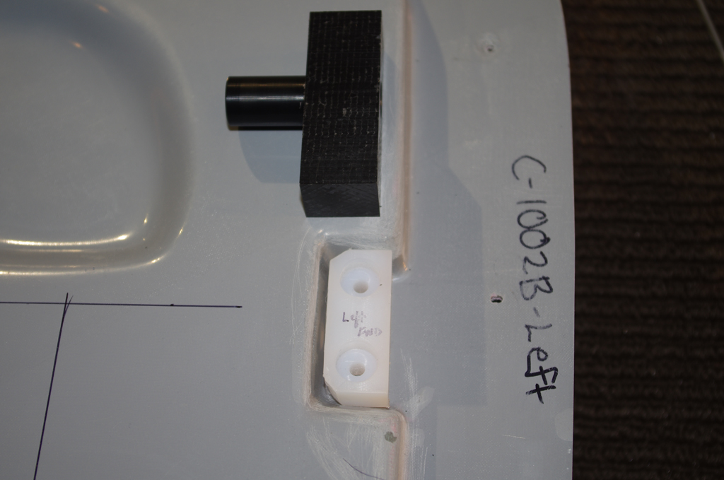 Now for custom fitting the Delrin pin blocks to the door frame. The white block from Van’s is shaped to fit exactly in the corresponding pocket, then used to match drill attachment holes through to the outside shell. The black PlaneAround piece has an extended pin guide and will also be custom shaped for the pocket. The existing holes will provide a template for the new pin blocks.