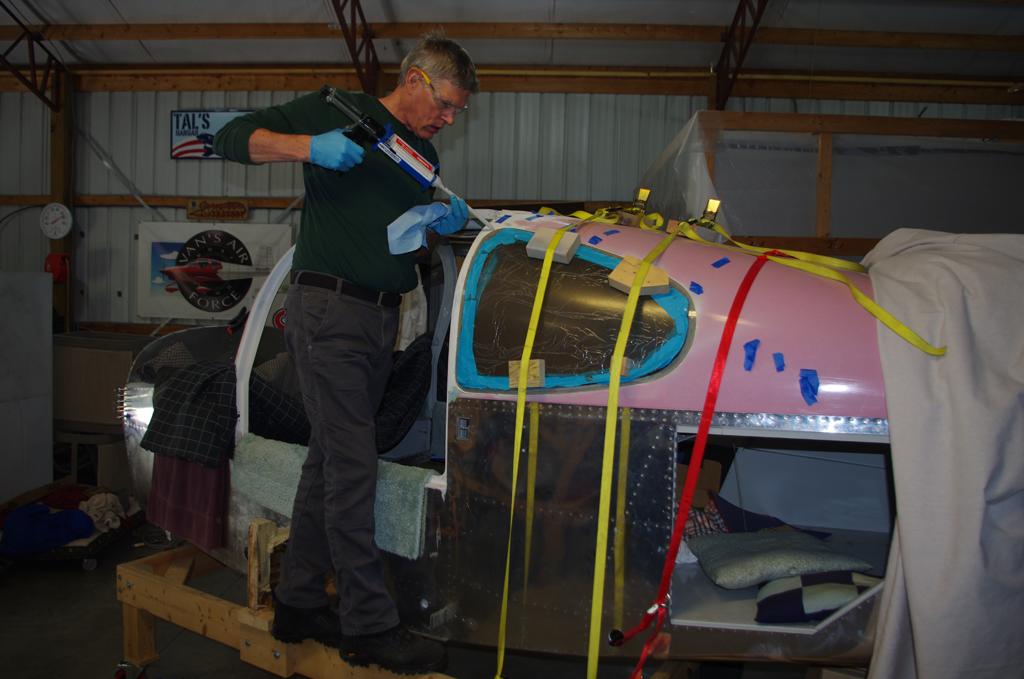
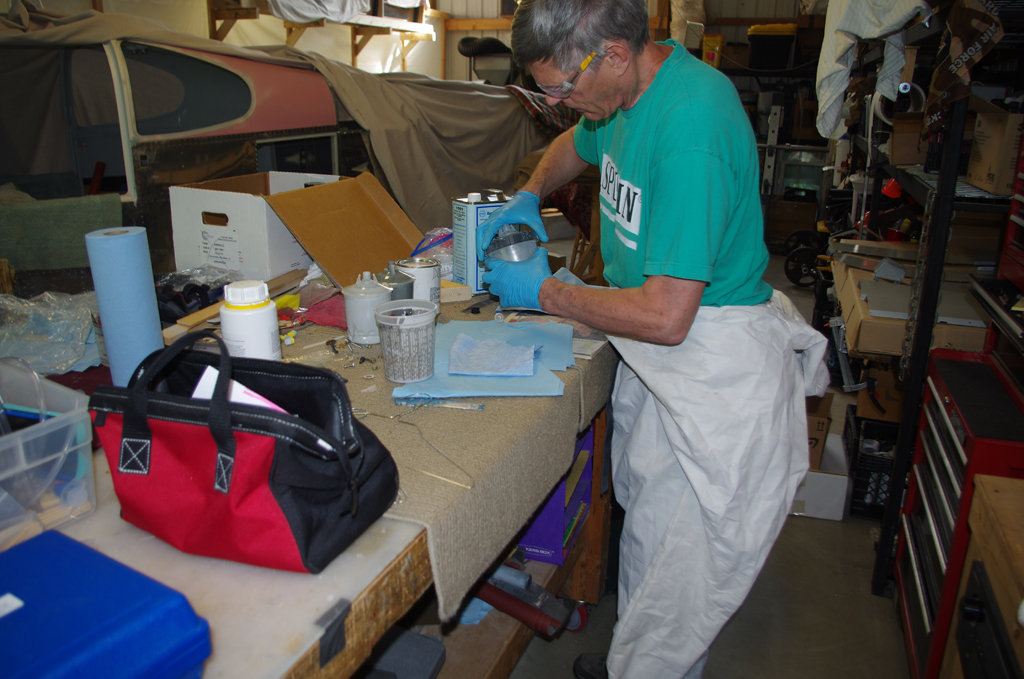
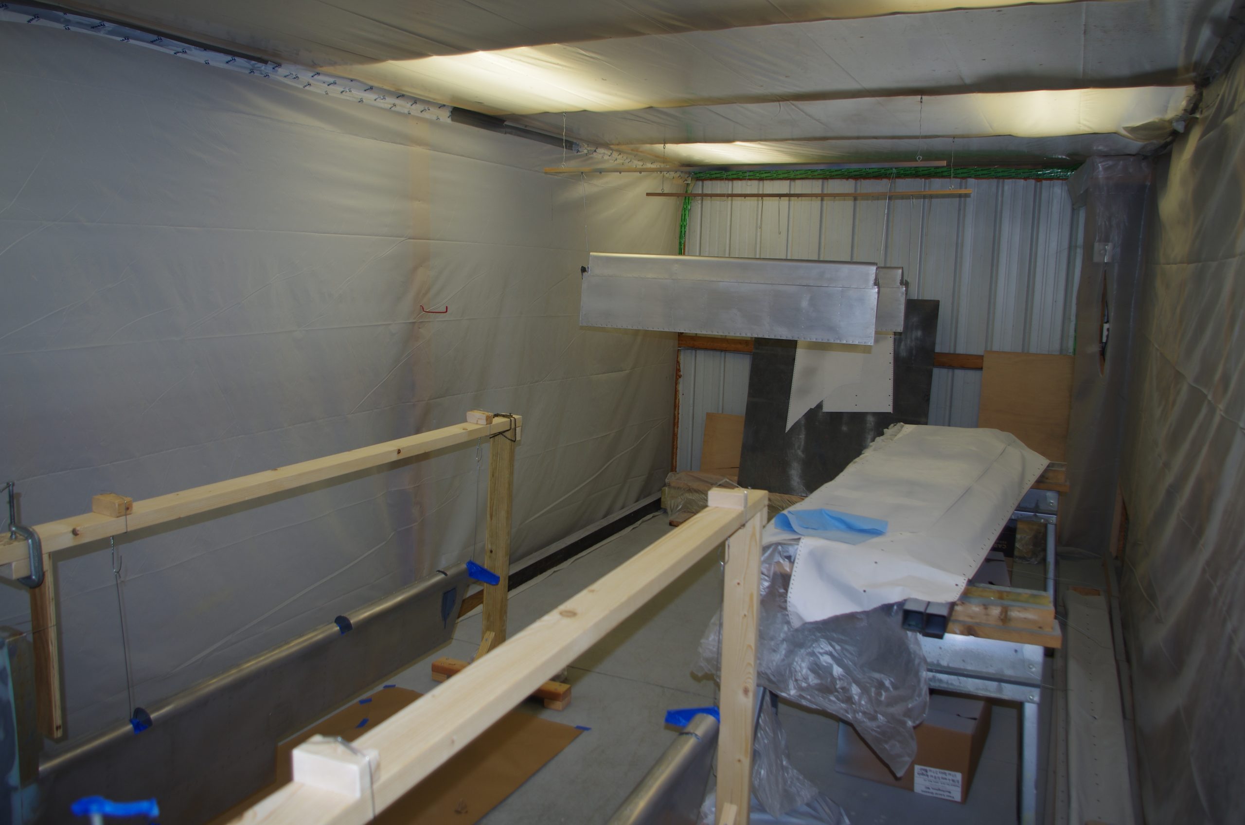
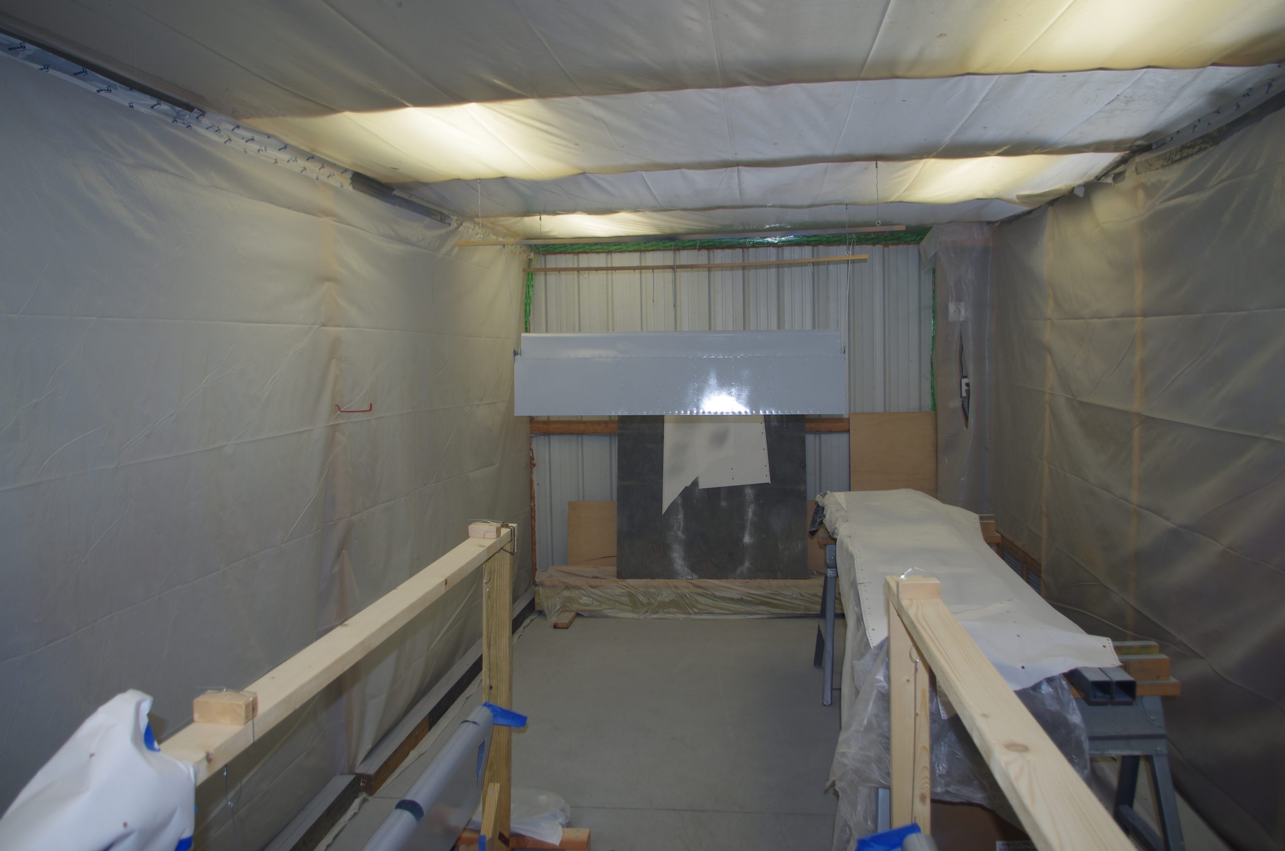
Now that many of the main components have been built, the next steps are prime and paint before final assembly. The tail section and smaller removable parts were the initial targets for this activity. I have been priming interior parts throughout the entire build, but this was my first experience with PPG CA7504 primer. The decision was made to switch to this product, which is specifically designed for airplanes. This primer is formulated with the elastomers, fillers and other ingredients for the flexibility needed to withstand rapid temperature changes, as compared to general automotive paints. This primer used in conjunction with PPG Aerospace topcoats prevents cracking, improves surface adhesion, and helps the mechanical characteristics of the paint layer.
The effort needed for painting takes considerable time, but is really not worthy of new posts. I intend to prime all exterior components, then seek assistance from someone to spray the final topcoats. I can perform the drudge work of preparations due to the time/cost involved, but am not confident enough to shoot a smooth, final surface. We shall see how this strategy goes.
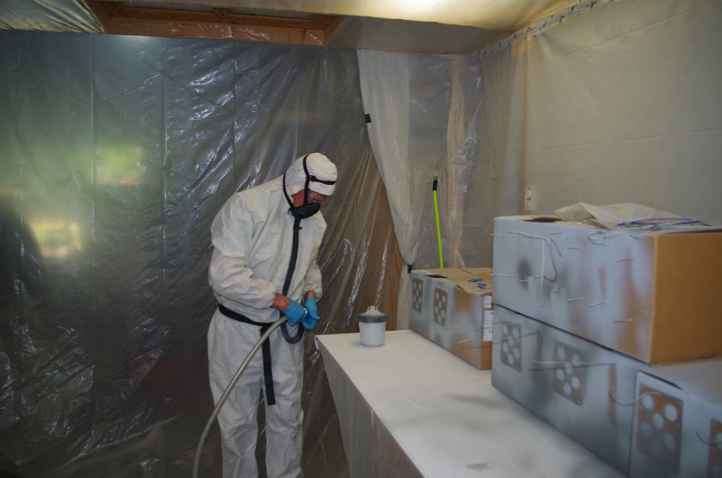 The general steps of surface preparation, mixing and spraying are the same as the previously used on interior parts using automotive PPG DP40LF primer. The new material requires greater attention to mixing ratios, measuring induction time with a Zahn #2 viscosity cup (15-18 seconds) prior to application, and modifying the application technique.

 Wing tips, rudder caps, and empennage parts were in the first batch. The outcome of the initial session were very poor, with runs and fisheyes. Subsequent attempts after sanding smooth and more rigorous surface preparations were much better. Additional filters were installed in the pneumatic air lines, and the lines were thoroughly purged of water and debris. Plus using higher quality Techline gun for better atomization and holding the gun further from the surface seemed to help. A few cycles of spray practice on the first batch have improved my technique to eventually yield good results.
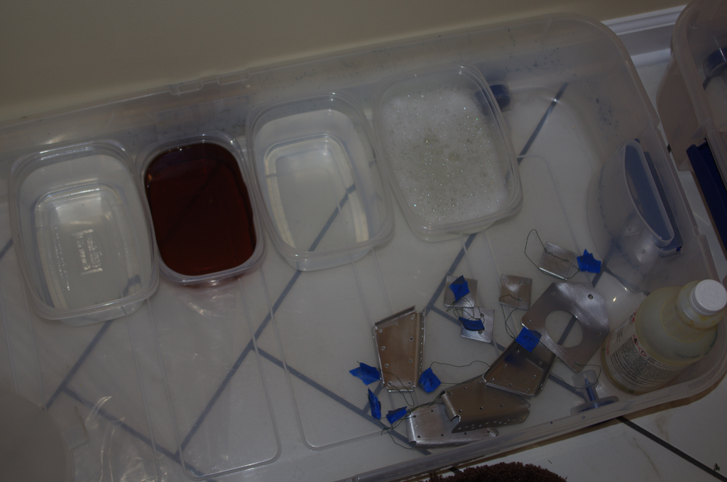
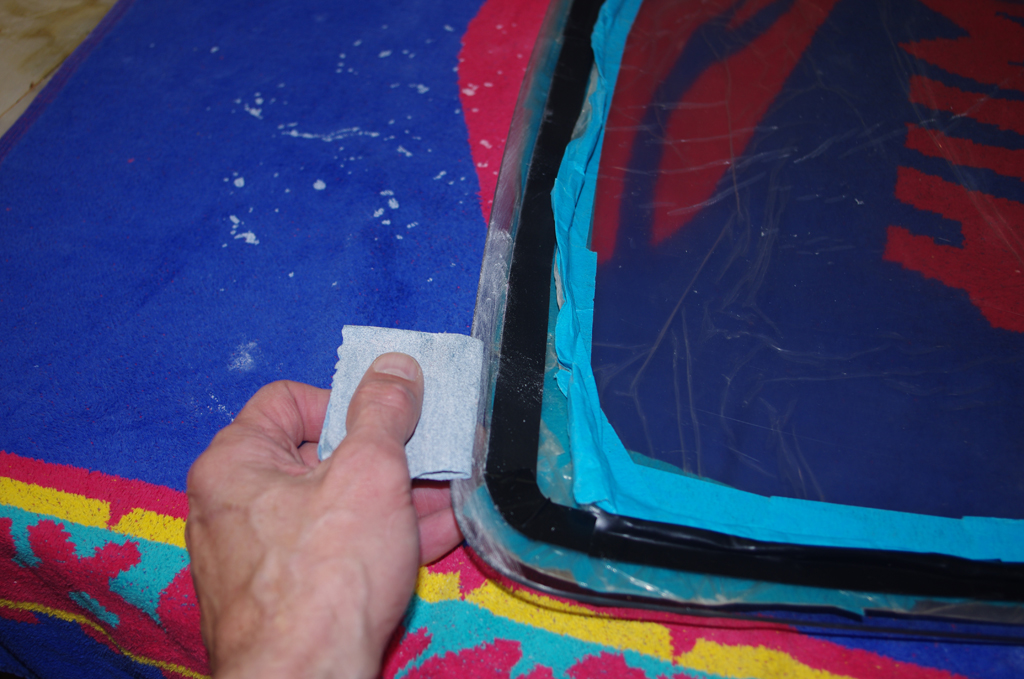
 Preparation steps include using a maroon (=320 grit) Scotch Brite pad in a palm sander to scuff the surface, clean with degreaser, condition with Prekote, then apply primer.
——-

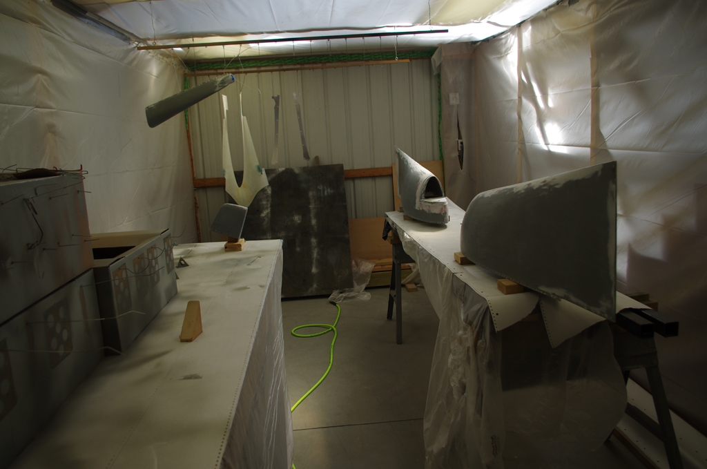
 The second batch on rudder and trim tabs worked out well with only one application session. Next up are elevators, ailerons, flaps and the horizontal stabilizer. The wings and fuselage will be last. More updates will be forthcoming when significant progress is made.

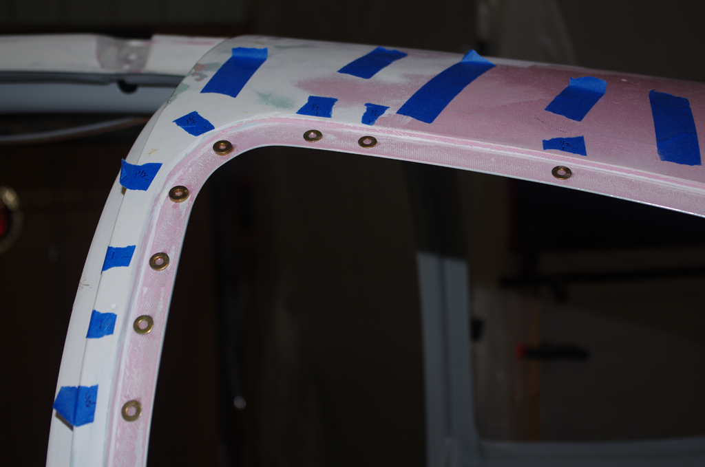
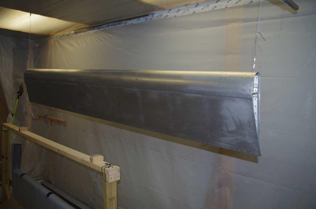
 Rudder (close-up and after second prime)(October)
 Ailerons (before and after priming)(October).

 Elevators (October)
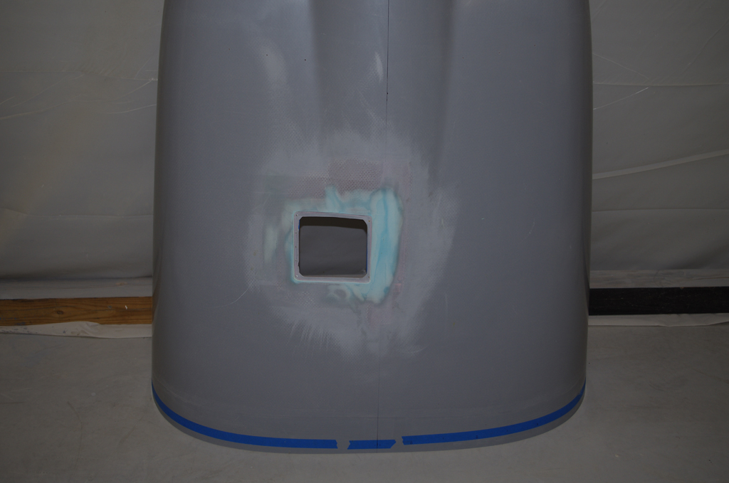

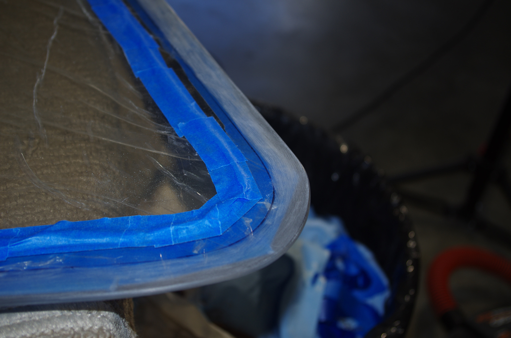
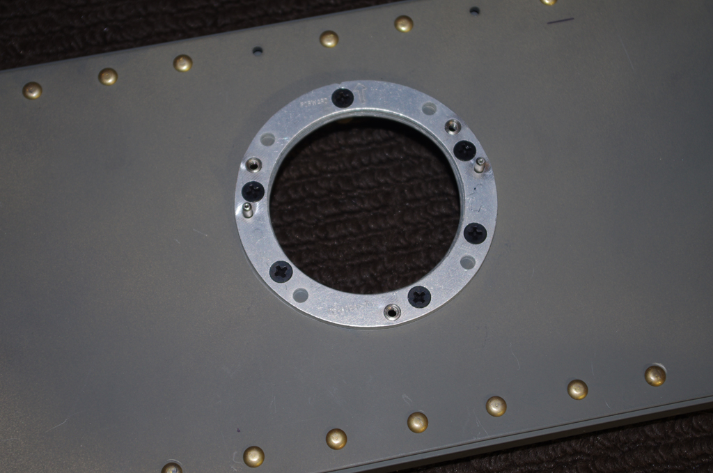
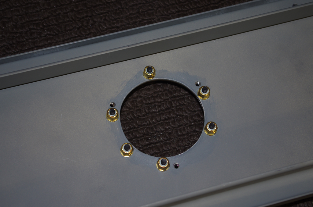
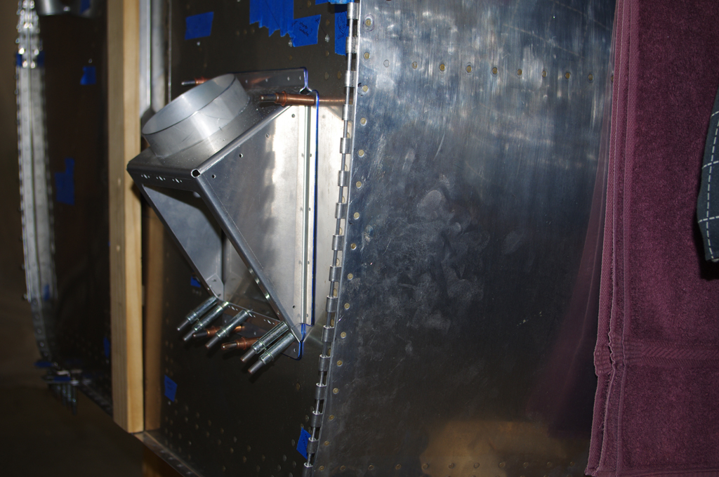
Oil door opening (November)
 Oil door cover (November)
 Flaps (November)
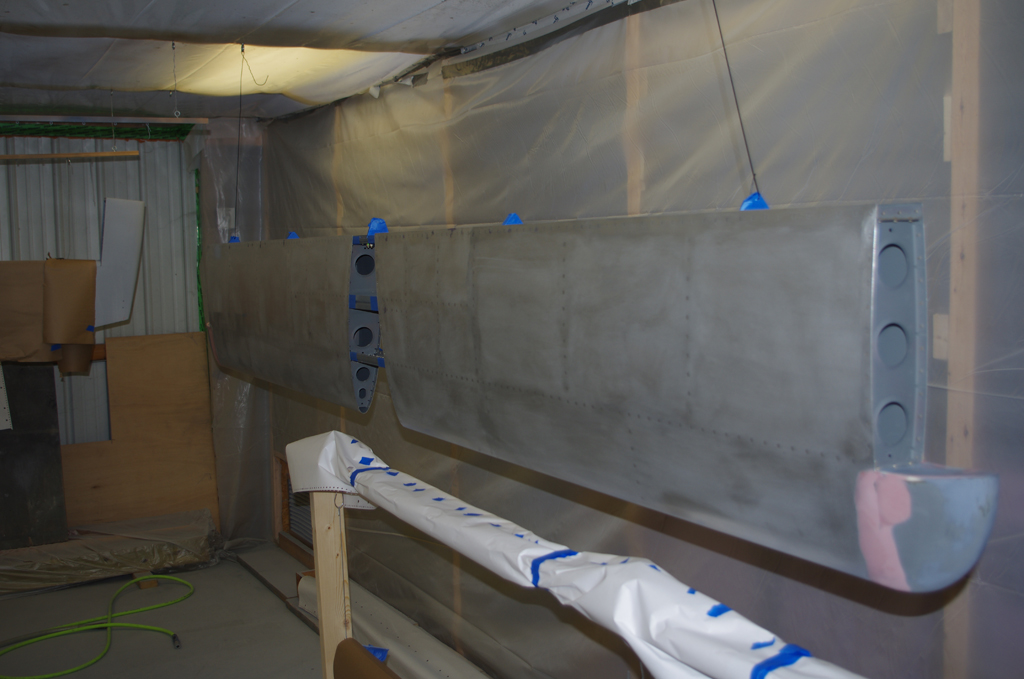
 Horizontal Stabilizer – tip (November)
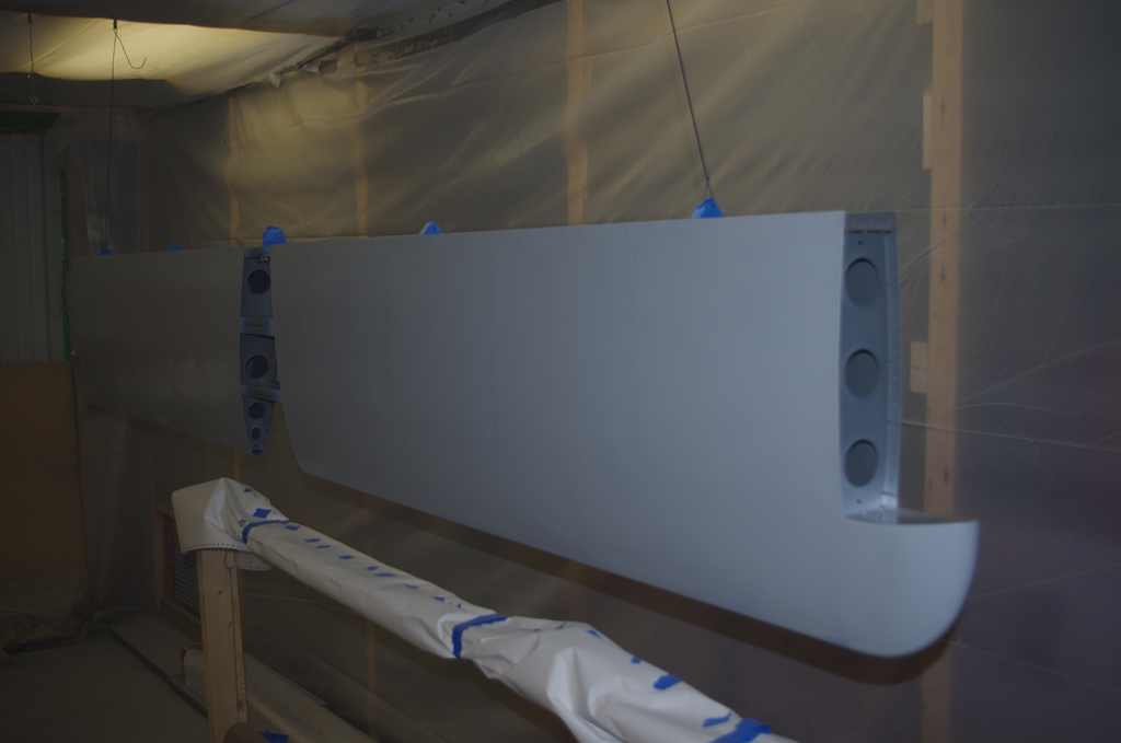 Horizontal Stabilizer (November)
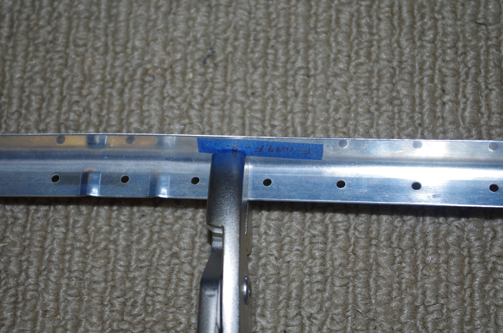
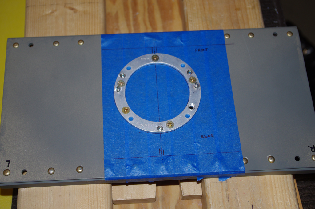
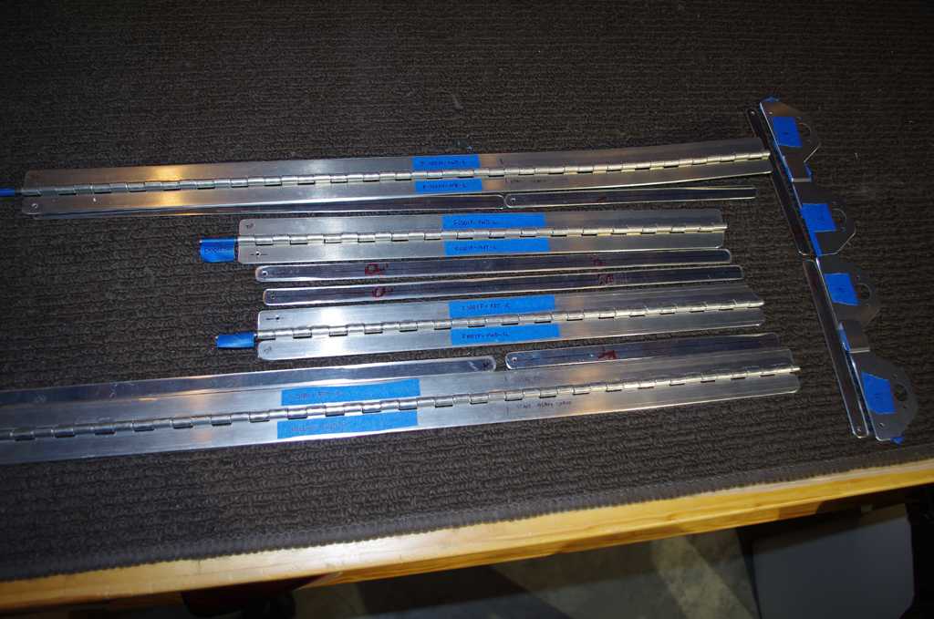
COWL HINGES
The upper and lower engine cowlings are attached to the firewall with 1/8″ PIANO HINGE. The initial sides and bottom pieces are shown.
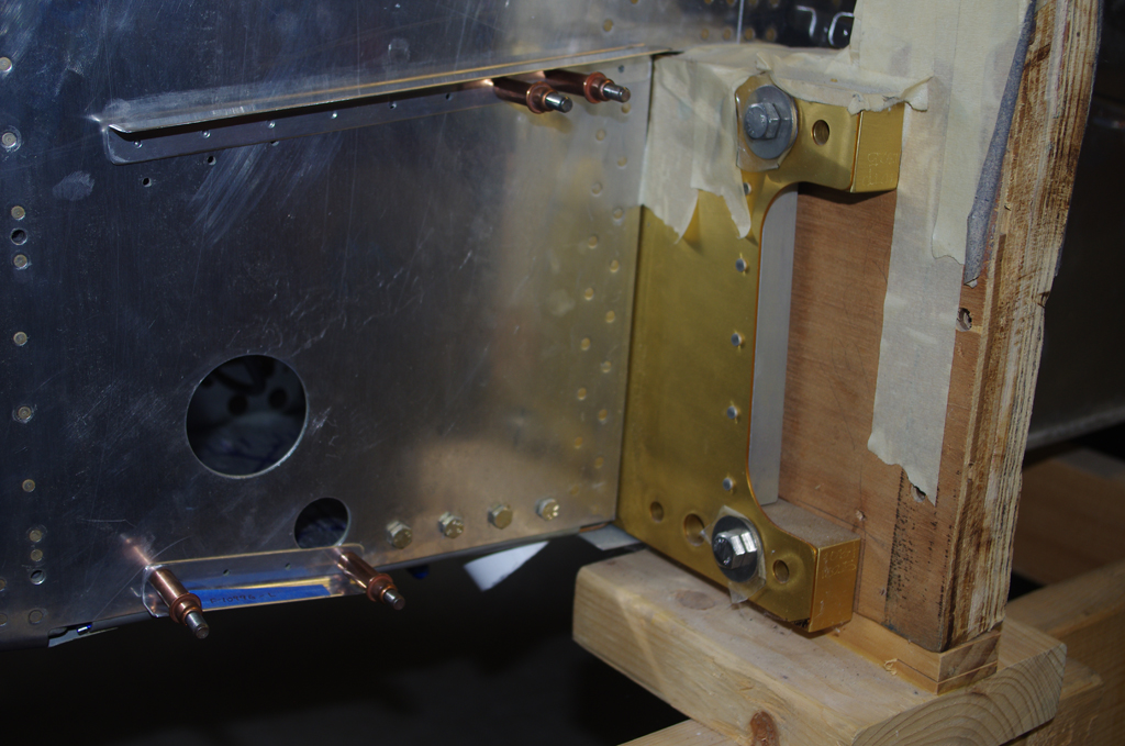
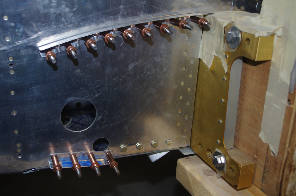
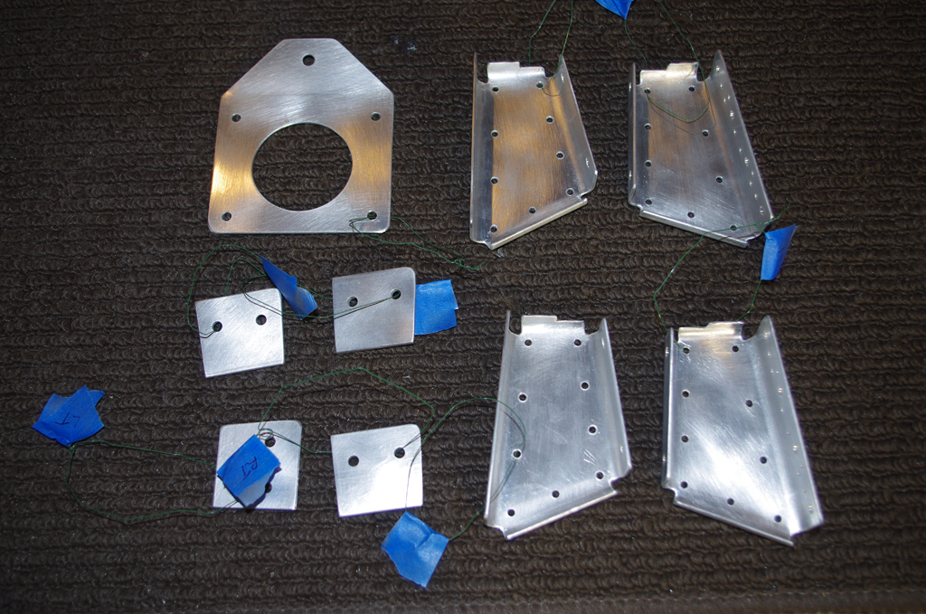
 Fabricated parts ready for fitting. The right photo shows the initial layout, then match drilling occurs next.
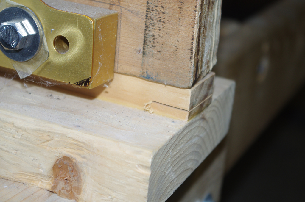
 Hand squeezing the side rivets was not so easy. The angle of the firewall-to-side and interference with the squeezer head was an issue. An number of rivets were later redone with a pneumatic jaw-type squeezer.
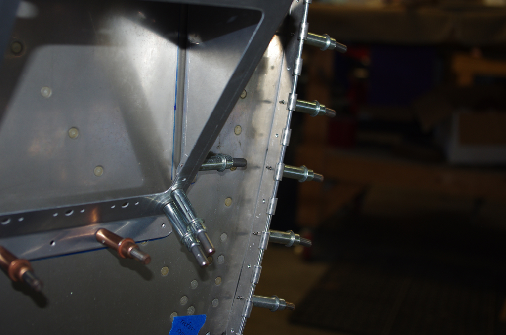
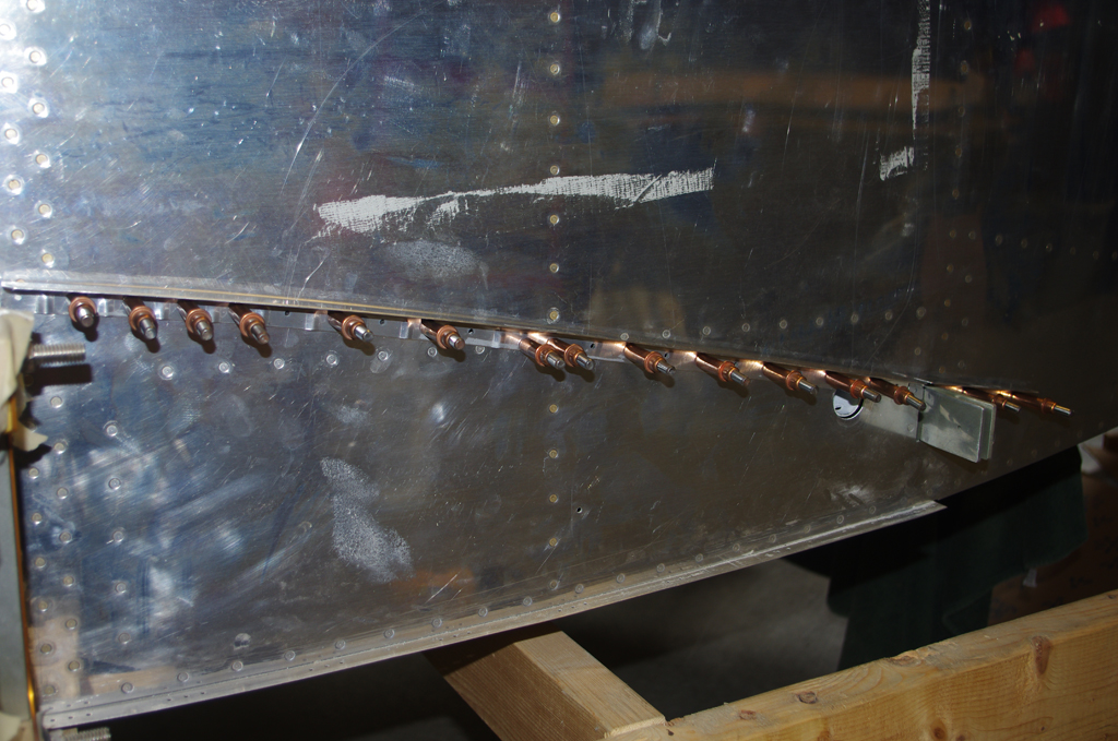
 Final results were not great, but acceptable.