Over the week Eric and I rolled the rudder counterweight skins and leading edges, then finished off with primer and pop rivets.
 Bending the skins around the counterweight is imprecise at best.
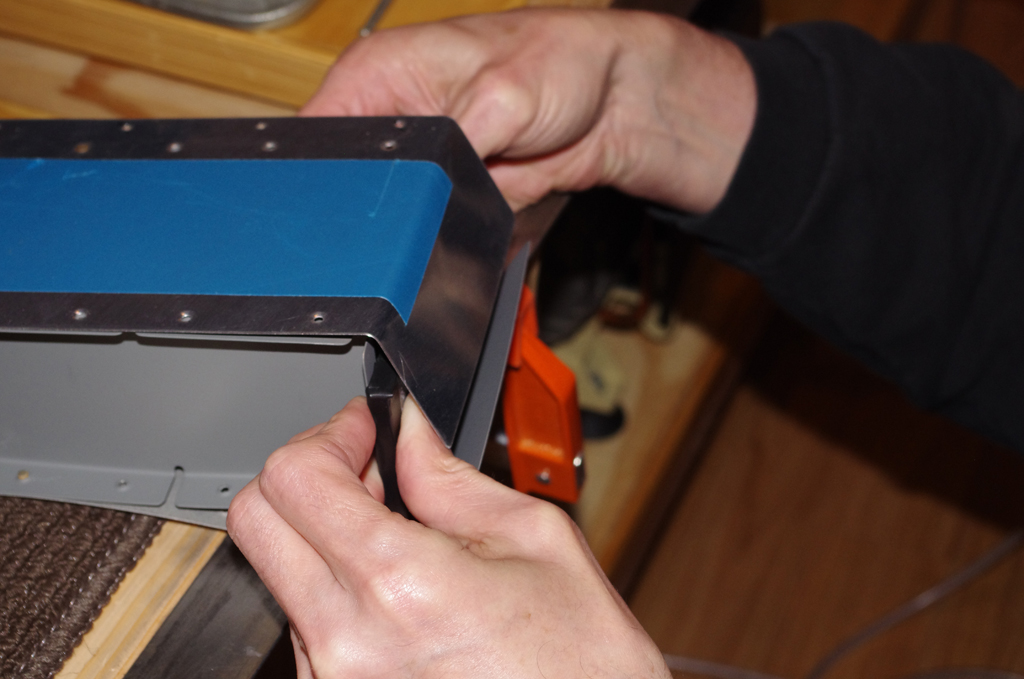
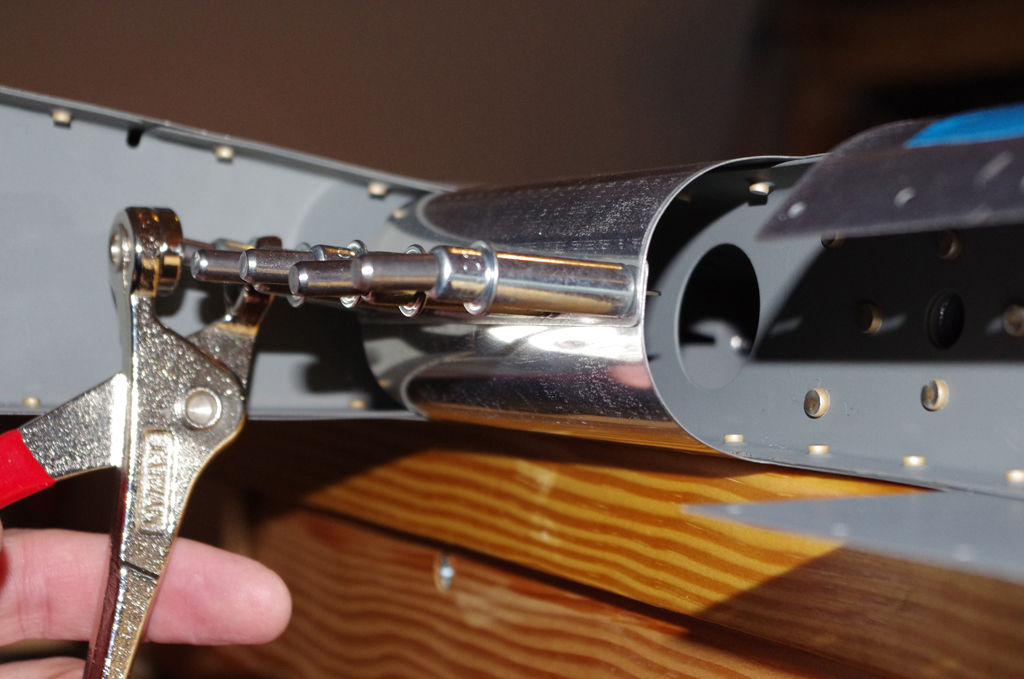
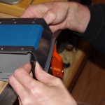
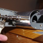
 Achieving a tight fit of the bent skins against the lead weight, but smooth with the fiberglass rudder cap, will be a challenge. Here I am fitting the weight in preparation for the first match drills.
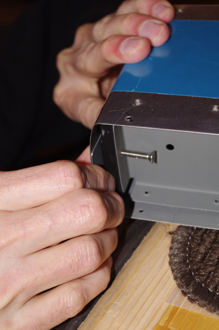
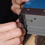
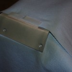 The inner skin will be overlapped with the outer skin, so a light application of SEM self-etch primer from a spray can is appropriate. The two #19 holes for the through bolts have been dimpled to match the countersunk holes the lead weight.
 The plans call for rolling the top section first, then middle, then bottom. A 1″ diameter wooden dowel was used to produce a good profile on the top section.
 A 1-1/4″ wooden dowel was used on the bottom section for the larger diameter turn. The forward edge could have been slightly rounder, but okay overall.
 The same priming technique for the overlapped section was implemented here.
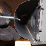
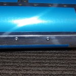 This shot of the middle section shows the final edge bend fastened with AD-41-ABS pop rivets. The primed part is just behind the forward face.
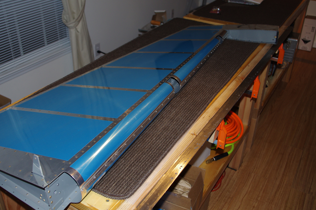
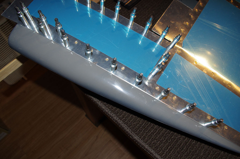
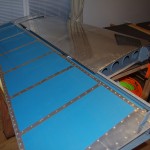
 Voila. A few dings here and there, but no major blemishes. Overall the effort turned into a satisfying and acceptable result.
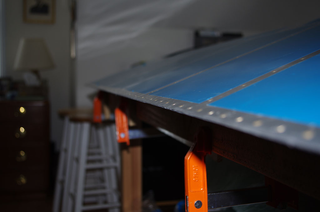
 Just for grins I positioned the rudder next to the vertical stabilizer to admire the progress (like thousands of other builders). Seems a long time coming, but at least real plane parts are starting to appear. An interesting side effect of this vanity staging was my recognition the VS spar flange almost totally obscures the forward edge of the rudder. This means my cosmetic concerns about the leading edge will only be visible to a select group of individuals prior to final assembly.
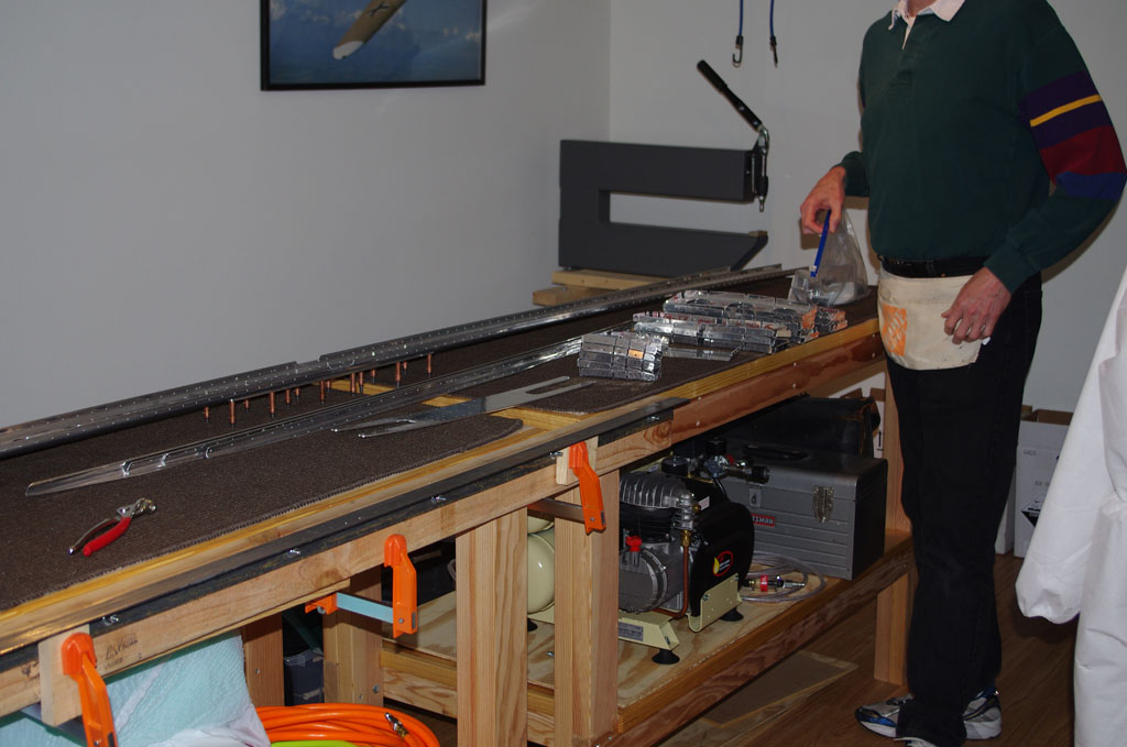
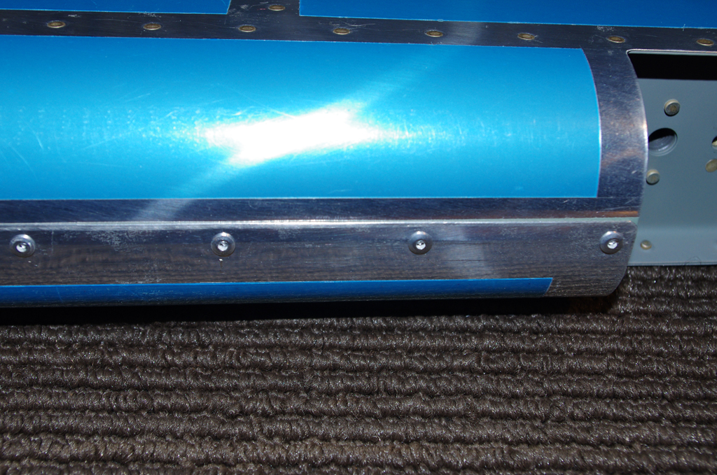
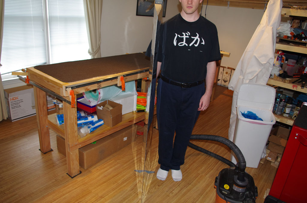
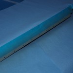
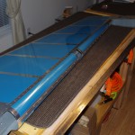
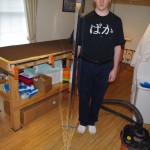 With vinyl now removed, this photo shows the trailing edge being nice and straight. Eric is in the picture for reference how big the rudder really is (sorry to cut off his head).
 On to the next assembly…
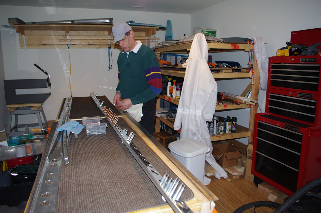
 This tray contains all the AN426 and AN470 rivets which came with the kit. Another has the pop rivets, another the screws/bolts, bonding strap/static wick materials, and so forth.