A variety of firewall forward components were added between paint preparation stages.

 Here the standard oil plug was replaced with a quick-change unit. Note the new unit is secured with .032 Safe-T wire tool.
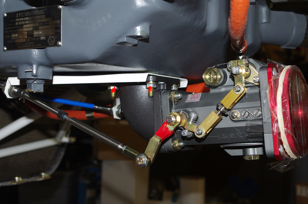
 Next the throttle and mixture levers were adjusted and tightened to final configuration. Castle nuts secure the levers and jam nuts immobilize the push-pull cables.

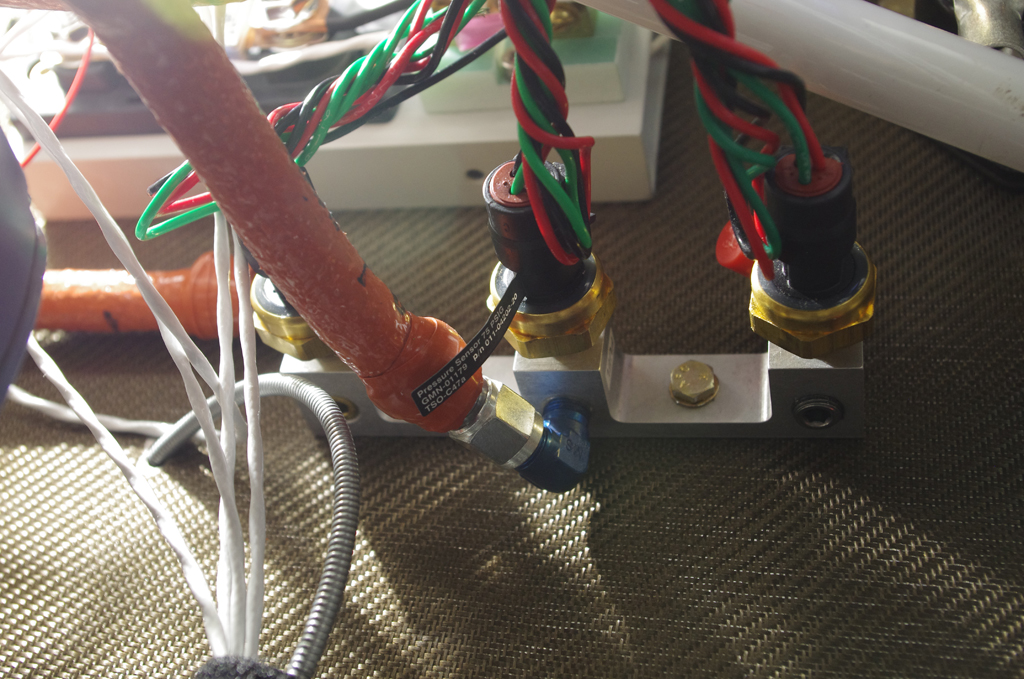 The sensor manifold contains units for oil (150psi), fuel (75psi) and MAP pressure (30psi). All sensors were sealed with fuel resistant lubricant and torqued to appropriate tightness. The manifold block was then fastened to the firewall through pre-installed (QB kit) AN3 nutplates.
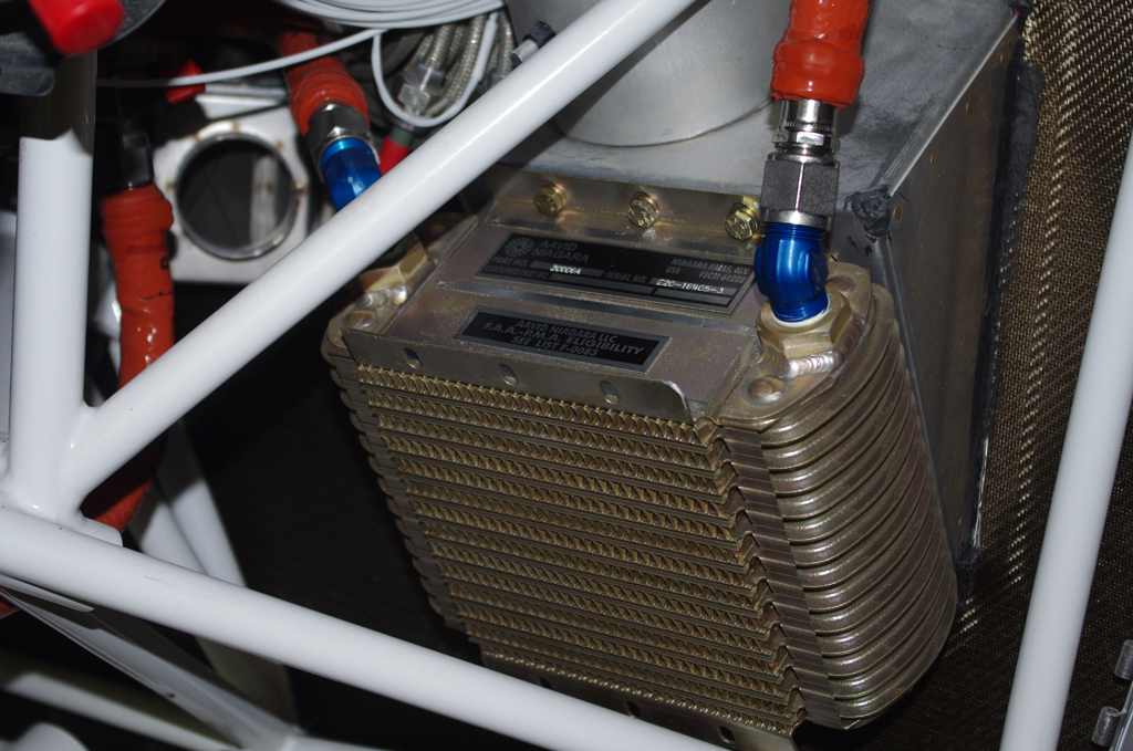
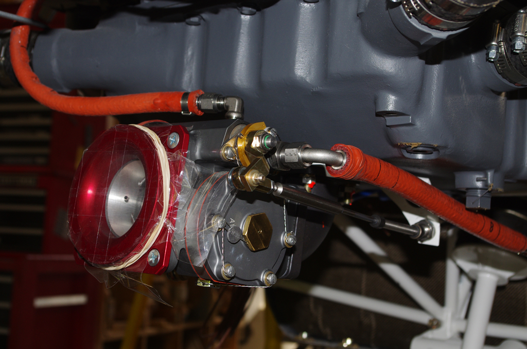
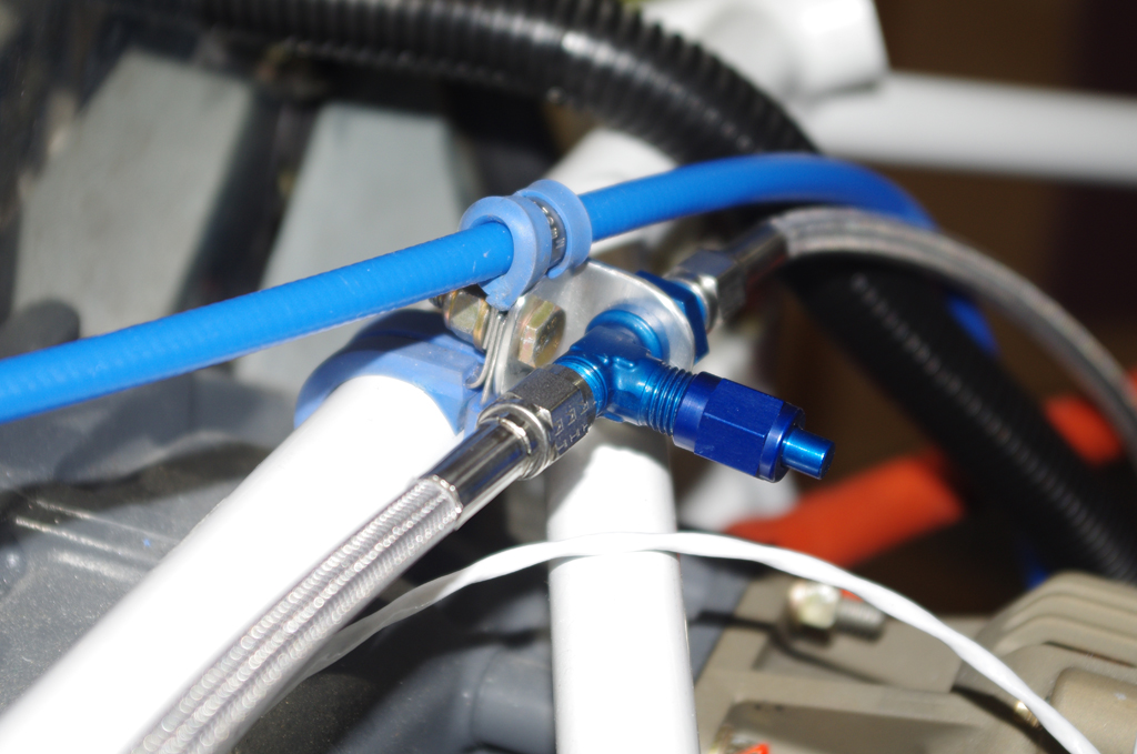 The oil cooler unit was installed and feed lines attached from the engine block. The right photo shows the manifold pressure line teed for a line to the Surefly magneto, which has the ability to adjust ignition timing based on MAP pressures.
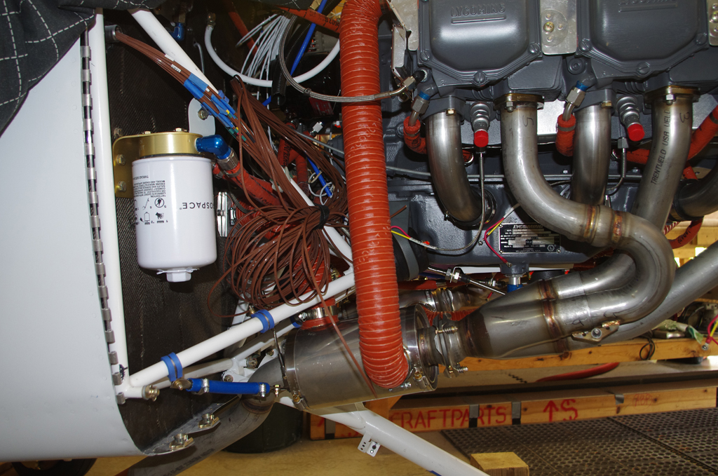
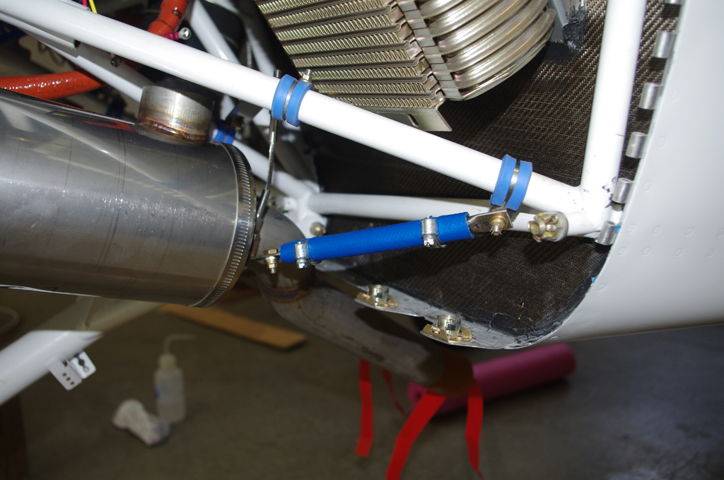
 A further complaint from many builders is oil leaking from the standard tube/hose/clamp configuration on Lycoming engines from cylinder heads to oil sump. I obtained the flexible SS hose kit from TSflightlines, then added fire sleeve myself prior to installation. Two notes – the fire sleeve was probably not necessary (overkill on my part), and access to the oil sump fittings was much easier without the exhaust headers being installed.
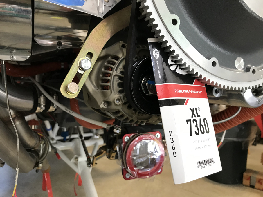 This shows a provisional install of the primary alternator drive belt (Gates XL 7360). Final tightening of the belt and torquing the retainer bolts will occur once the propeller has been mounted.
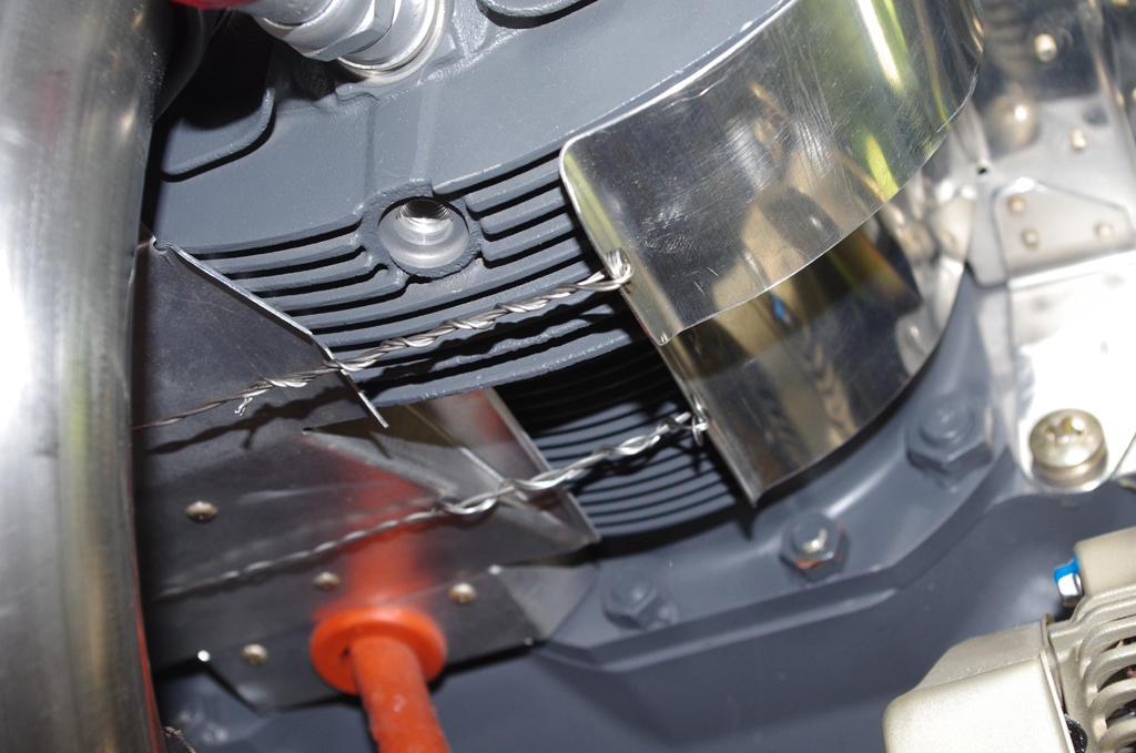
 The right photo shows the open ports for CHT probes in the cylinder head, plus the .032″ safety wire approach used to hold the forward cylinder baffle flange. The other photo shows the CHT probe installed with 30 lb-in torque (as per manufacturer instructions). The probes still need to be attached to the GEA24 engine monitoring system.

 Exhaust headers and exhaust pipes with heat muffs were installed. Then 2″ SCAT tubes were connected between the engine baffles and the exhaust muffs. Finally additional SCAT tubing was run to the heater vent distribution box.
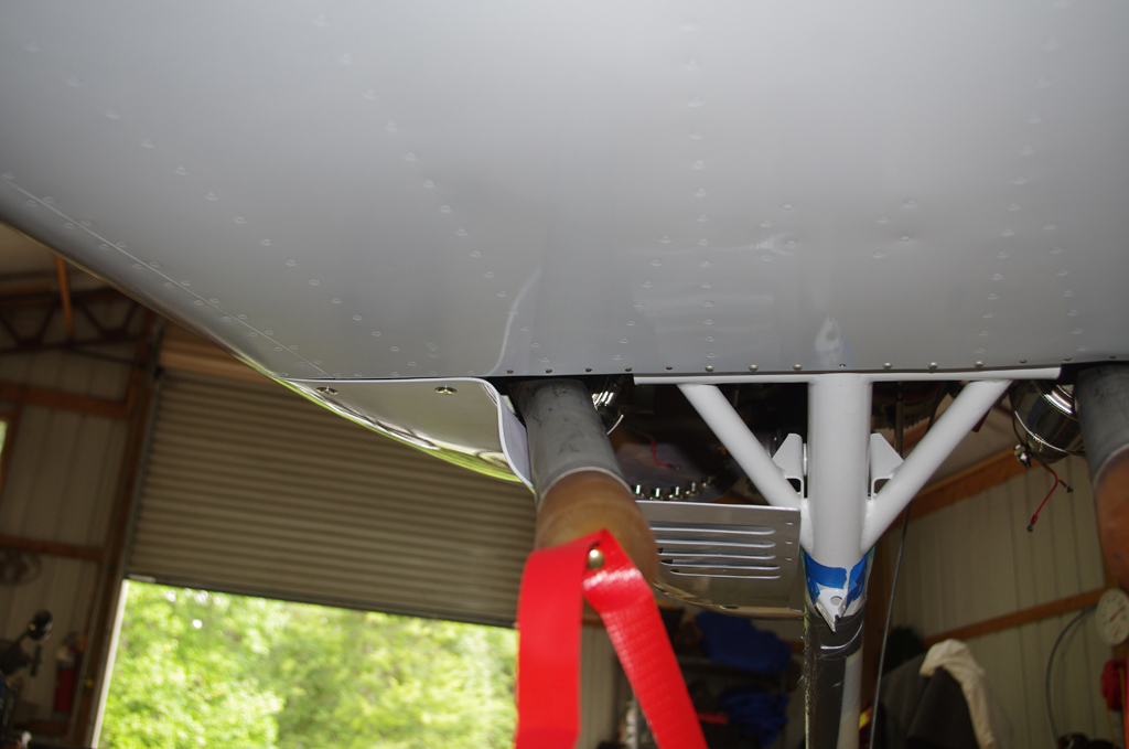 The exhaust pipes have a flexible ball connection with the rigid exhaust headers. An isolation kit resides between the engine mount and exhaust stack to correctly position the output orientation. It also serves to keep high temperatures off the engine mount. About 1/2″ – 3/4″ separation was achieved between the exhaust pipes and the lower cowl sections. Later the cowls will be covered with a thin ceramic blanket and reflective aluminum shielding to keep engine heat from discoloring the cowl paint.