The aileron push rods must first be set into a ‘neutral’ position before the trim servo motor can be properly aligned and measured. The objective of this exercise was attach the aileron trim spring brackets.
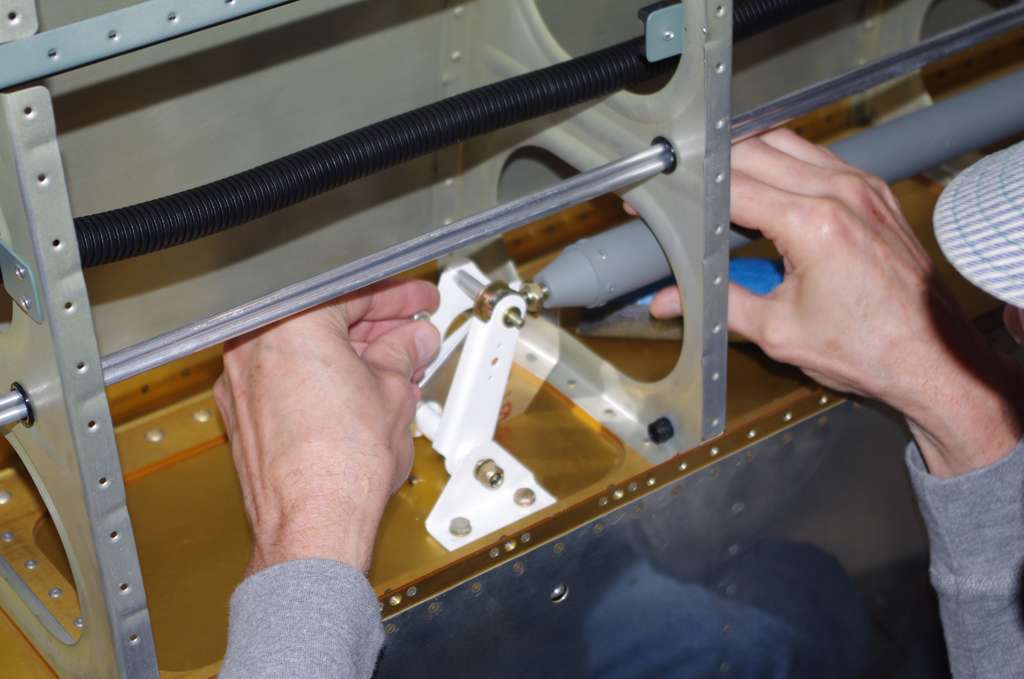
 The left picture shows attaching the aileron push rod end to the outboard pivot actuator. The inner push rod end connects to the aft arm of the aileron torque tube in the wing root. A bearing for the torque tube must first be installed in the tank spar.

 The sealed tanks (see below) were then installed in the wings – capturing both ends of the torque tubes during the fitting process. These tubes could be installed with the tanks already attached, but the process was much easier with the tanks off.
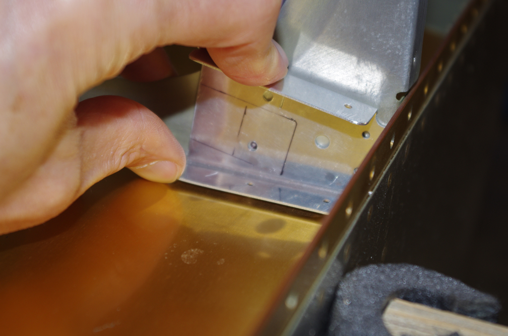
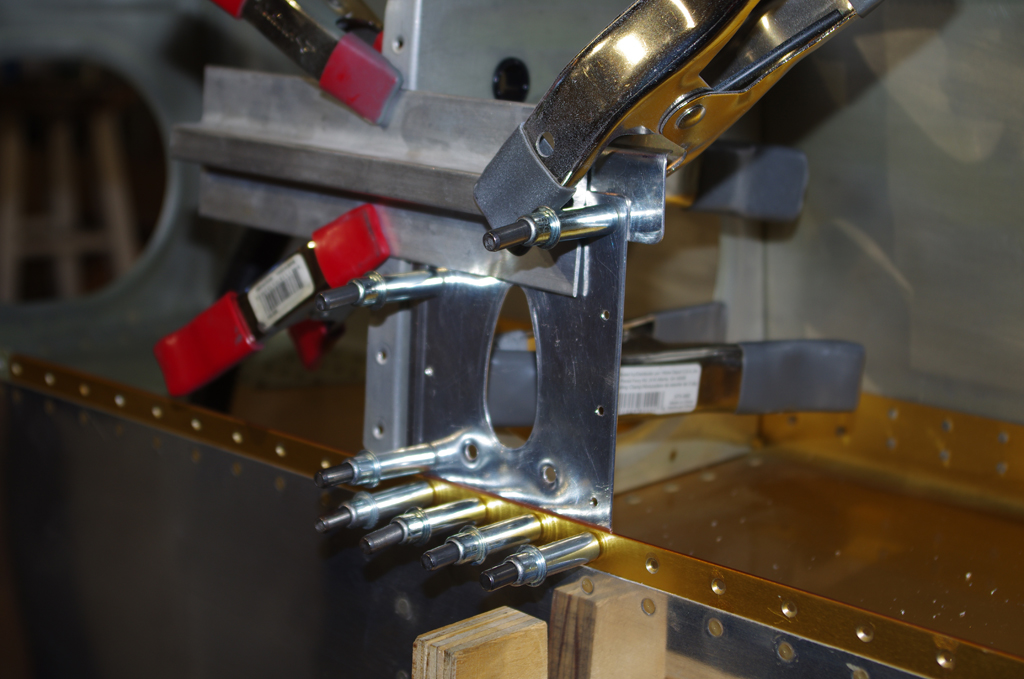
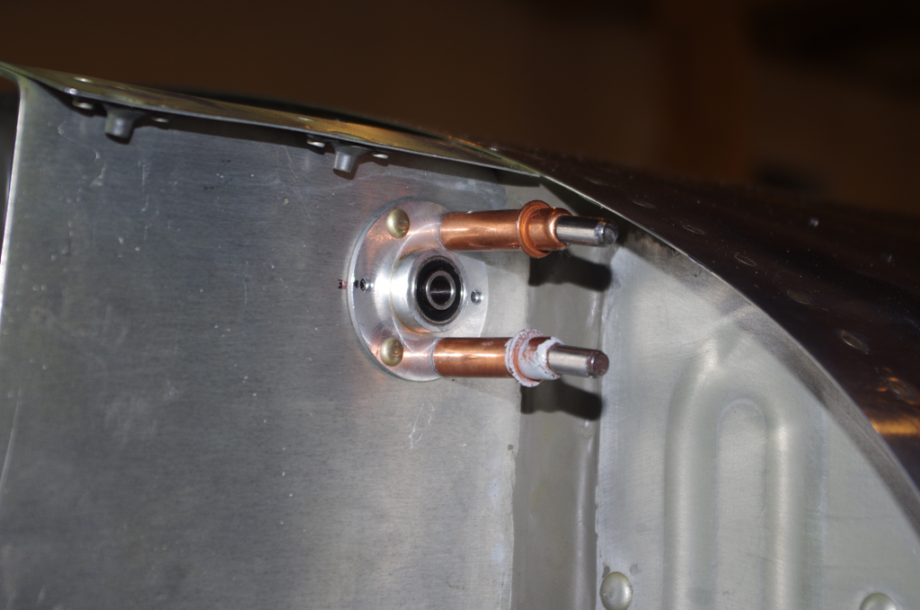
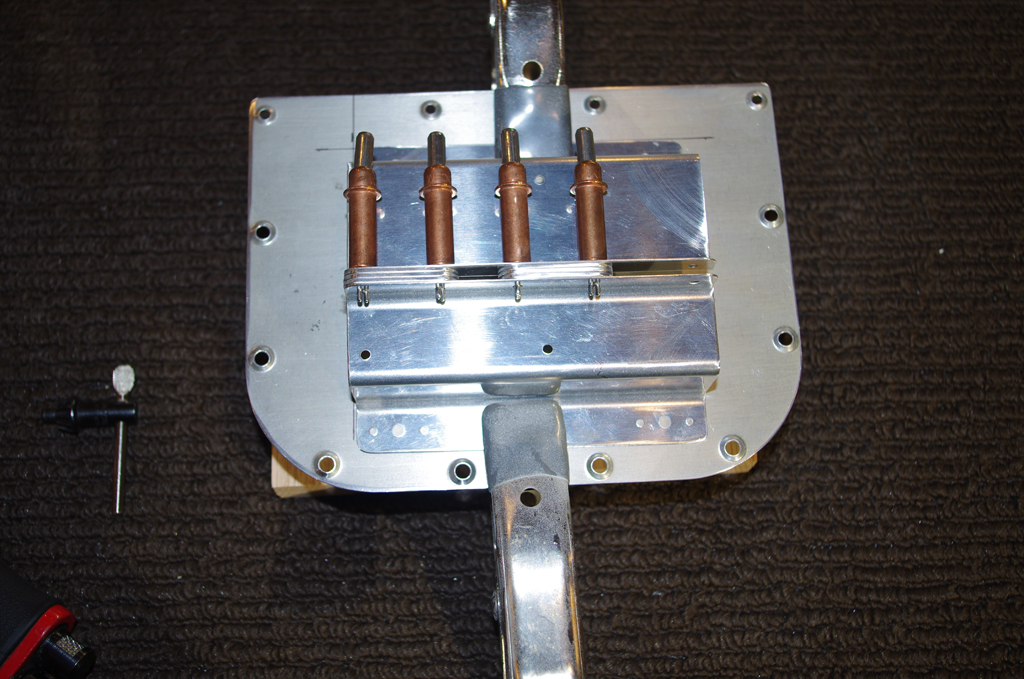
 Here are close-ups of the torque tube connections in the left wing. Notice the jig in the left photo created to position the push rod. The final push rod end lengths were adjusted to neutral with the jigs, then the jam nuts were tightening to hold everything firm.
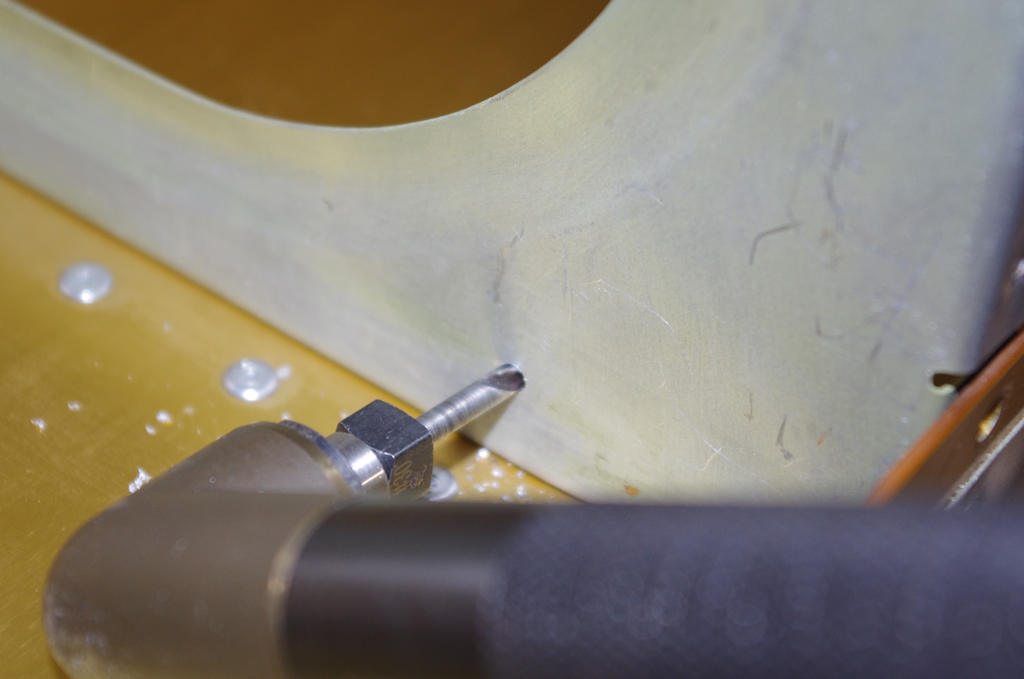
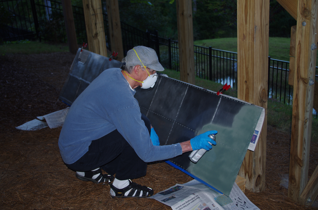
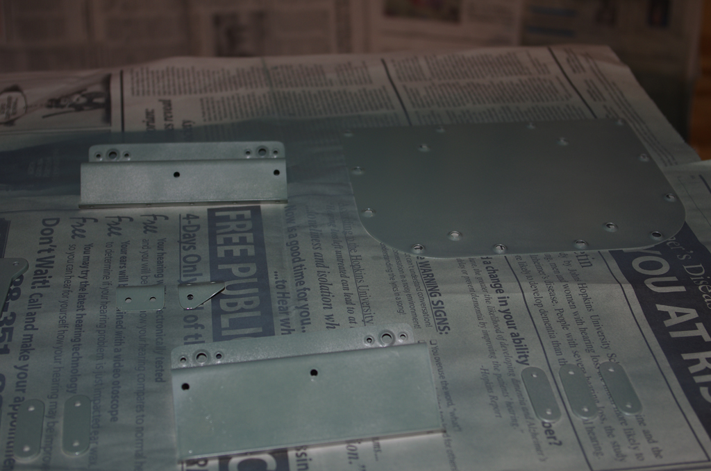 Now began fabrication of the trim servo bracket. After cutting, smoothing, and deburring the trim bracket was provisionally assembled with clecoes. The inner left inspection plate was then match drilled as the base for the trim bracket. A coat of SEM Self-Etching primer was applied to all surfaces.
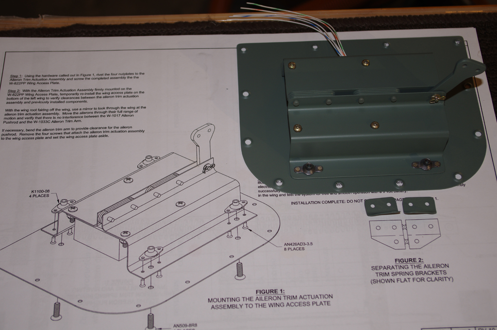
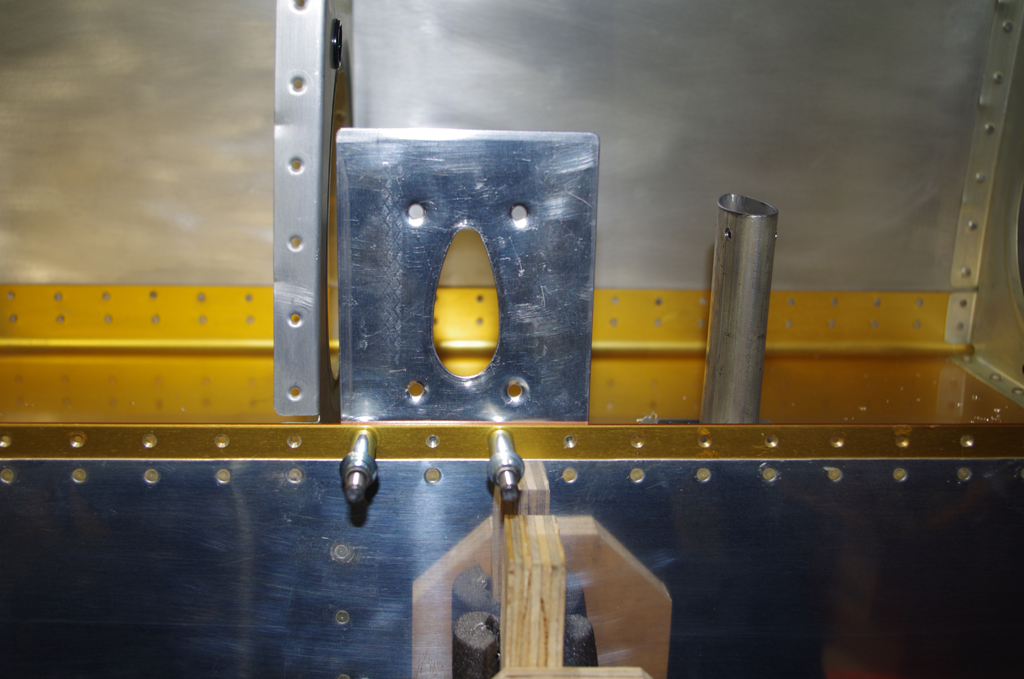
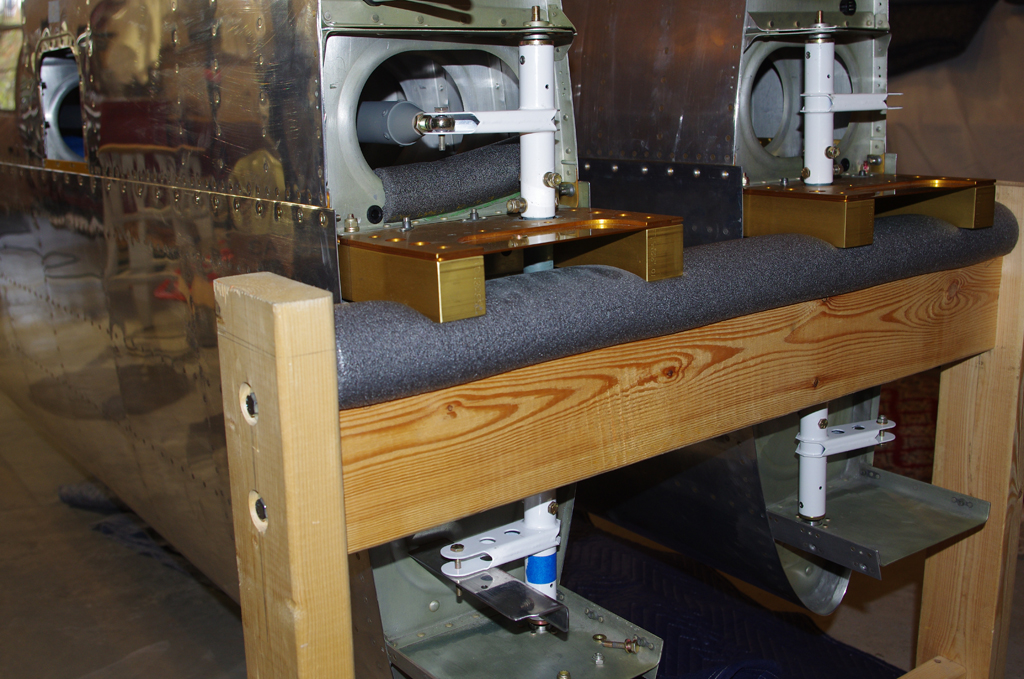
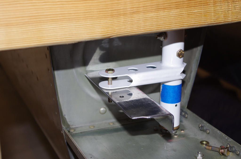
 Top and bottom views of the assembled trim servo in the bracket and the modified inspection plate.
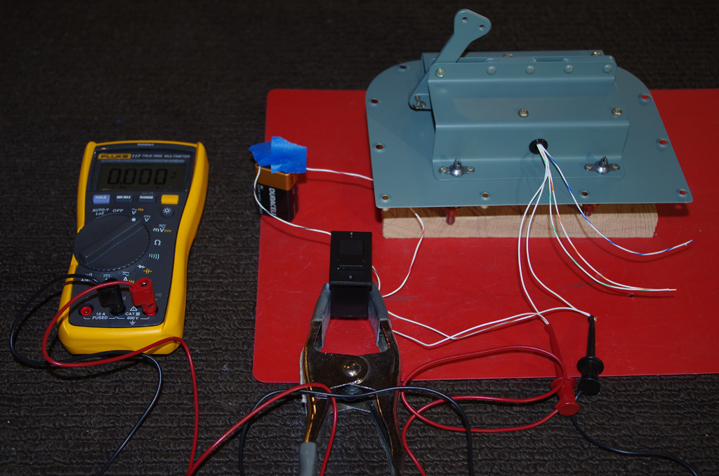
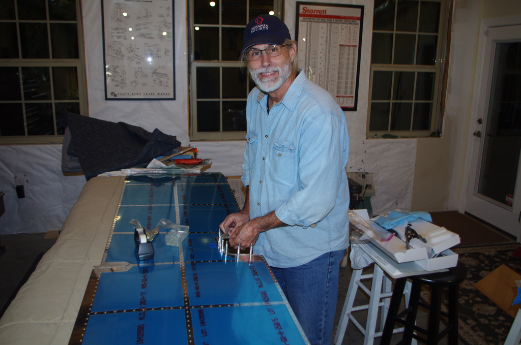
 The supplied Ray-Allen trim switch was connected between a 9V battery and the servo motor. A Fluke voltmeter confirmed electrical contact during operation. The motor takes ~27 seconds to move from the inner to the outer position. This measurement and actually marking the two position limits were used to locate the center of travel for the aileron trim arm. This measurement was transferred to the neutralized push rod via a parallel angle channel and a square.

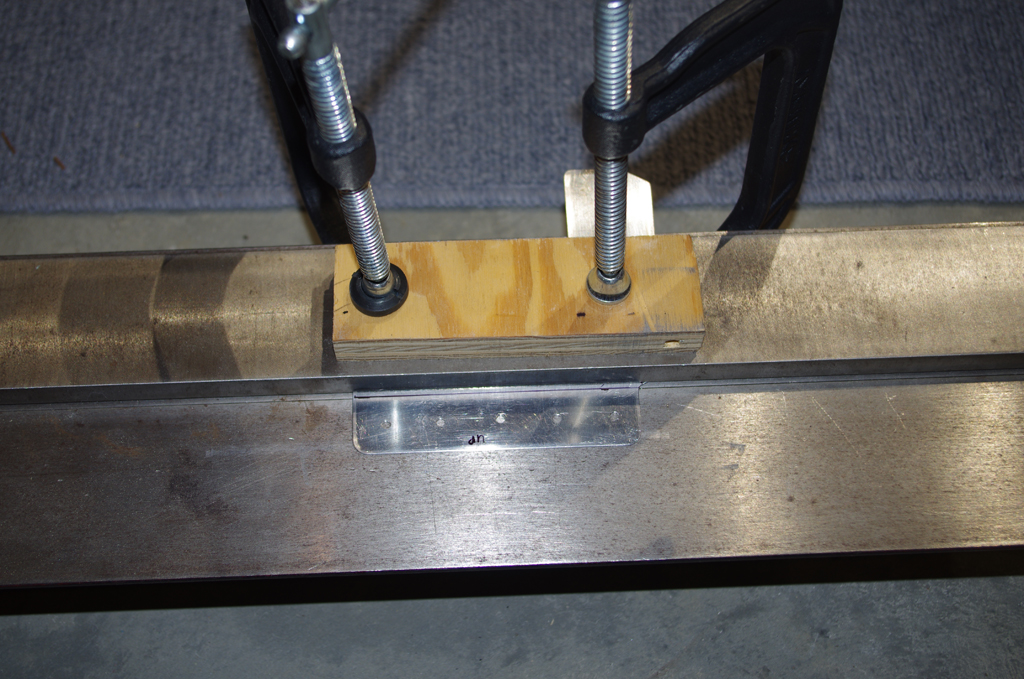
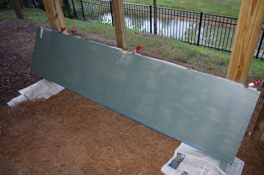
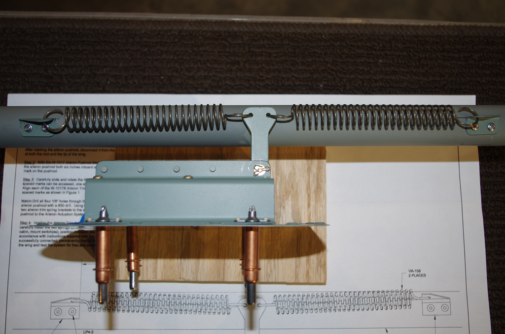 The photo on the left shows prior to riveting, and on the right the final configuration. It will be a challenge to install the springs once the push rod is permanently installed in the wing.
FUEL TANKS
=============

 The quick build fuel tanks were removed for leak testing prior to aileron push rod adjustment. My A+P friend Terry filled each tank with 30 gallons of aviation fuel for a week. No leaks! Once final wing assembly is complete, removing the tanks for leak correction would be very difficult. So just for good measure, all the rivets and seams on the spar side were also covered with a generous portion of Van’s tank sealant (similar to ProSeal).