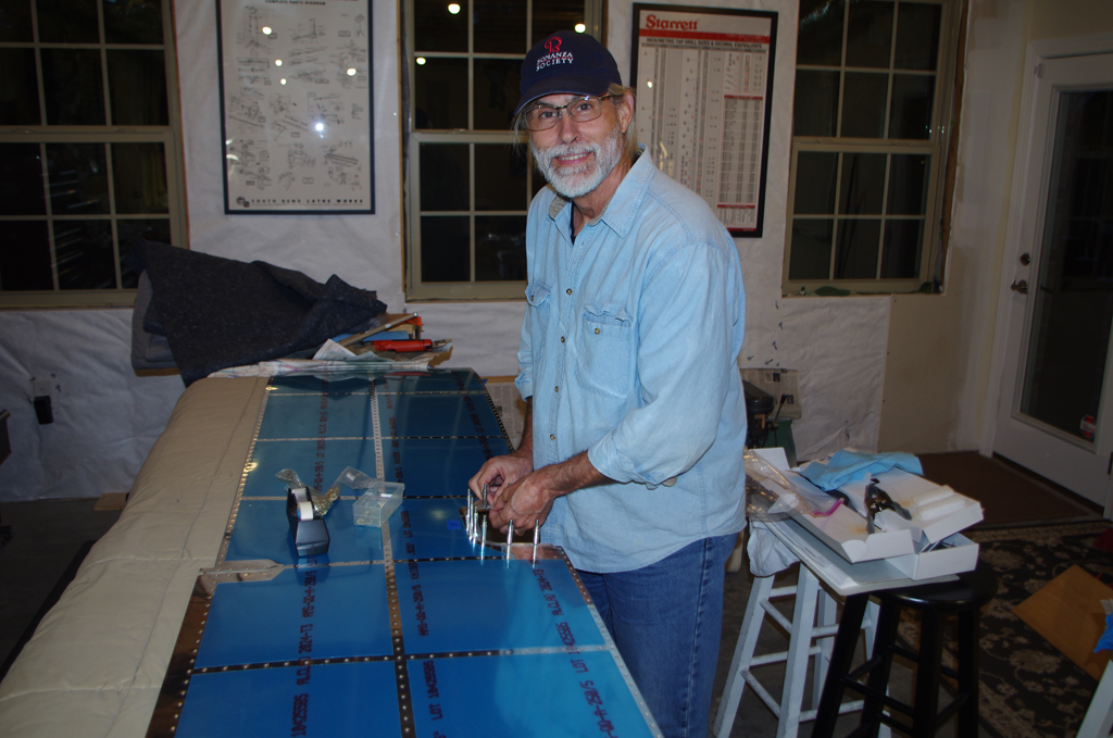
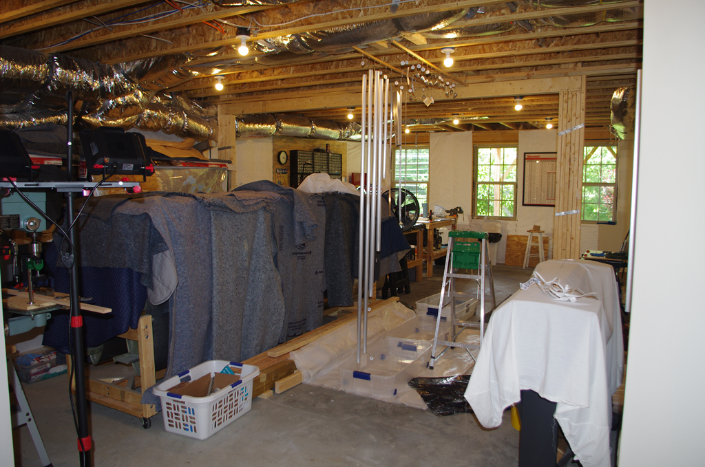
A series of miscellaneous activities were performed on the wings in the last few weeks. This work was staged before any final riveting the bottom skins, as access is so much easier with the skins still off.
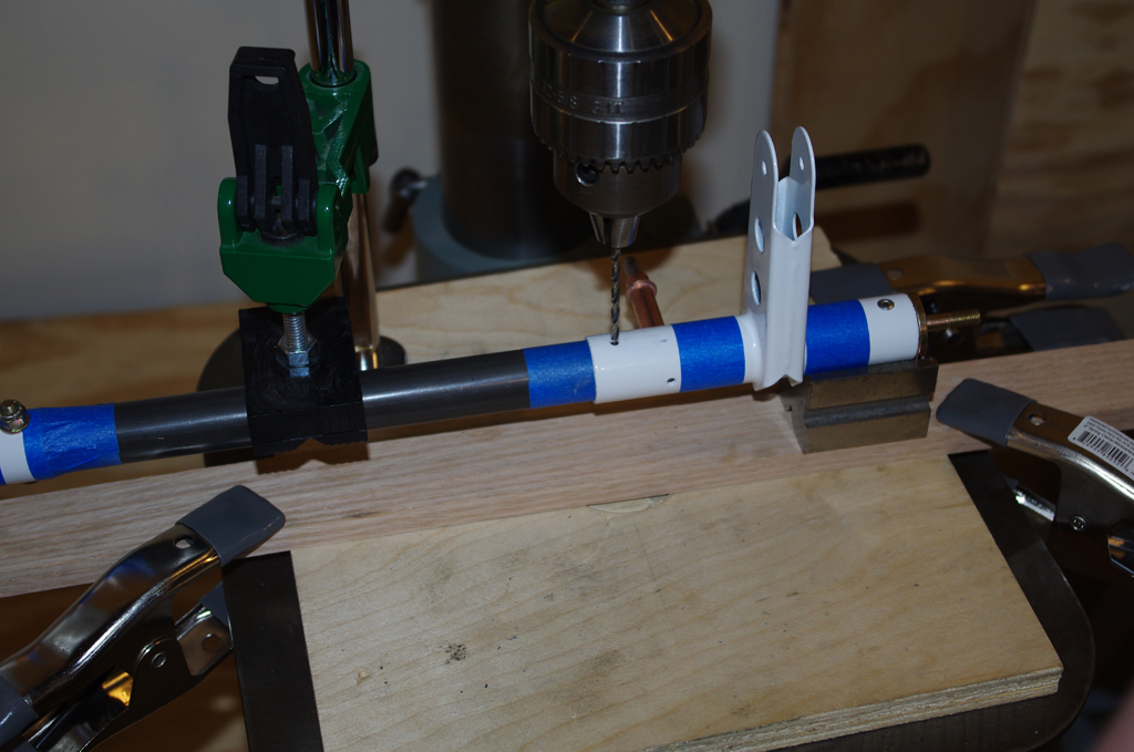
 The quickbuild wings come with a main wiring channel in each wing. These roughly 5/8″ diameter hole have nylon inserts and are intended by Vans for the wingtip wire bundles. Because of added electronics for heated pitot, aileron trim, autopilot servo, and the like, I wanted addition channels (thus the custom wire brackets from previous posts). I also wanted dedicated grounding lines to the wingtips, so additional channels were created. Here a template is used for reproducing the hole placement in the wing ribs.

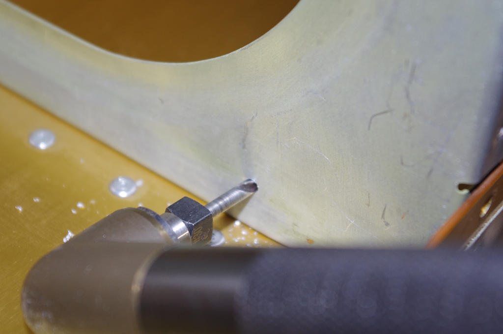
Once measured, the 7/16″ holes are punched and then drilled with an angle head holding threaded bits.
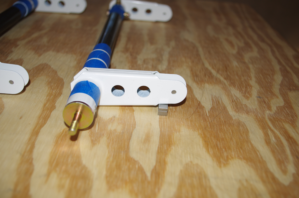
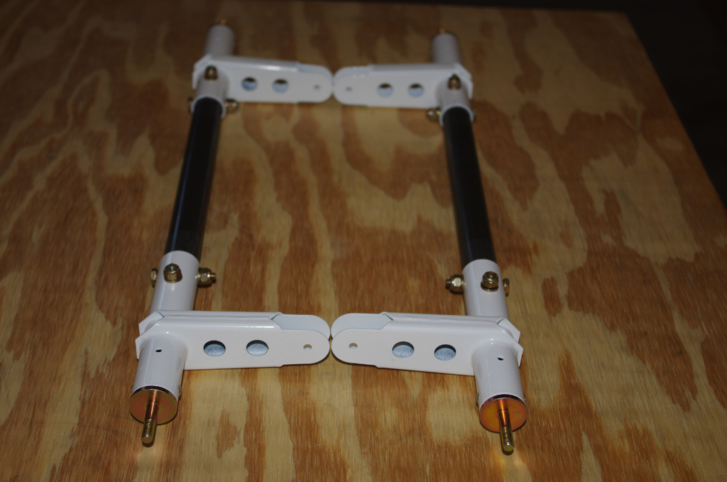
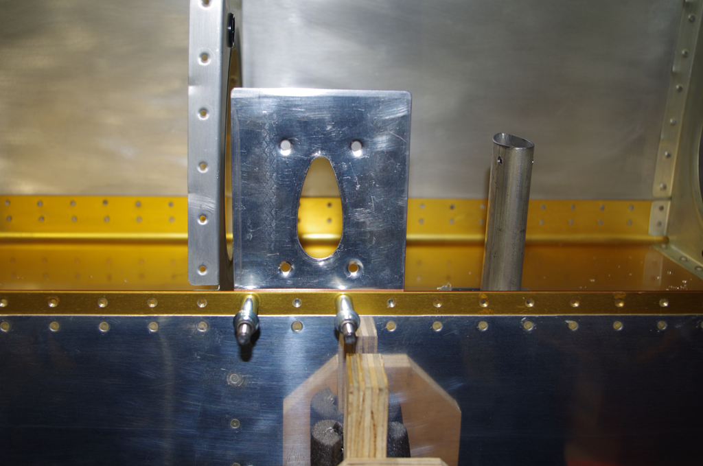
 The final configuration of each wing has three available channels, two through the ribs and one wiring chase attached to the custom brackets. For the left wing, the 1/4″ soft aluminum tubes for the pitot and angle-of-attack (AOA) indicator will be fed through the larger of the runs through the ribs.
==================
PITOT MAST
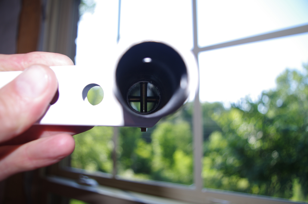
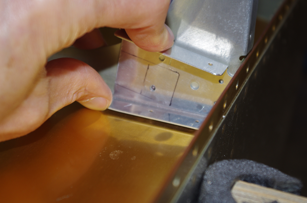
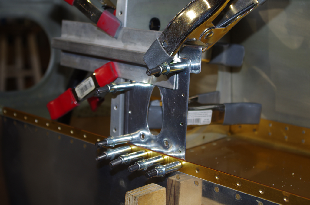
 A Gretz mount for a Garmin heated pitot needed to be crafted in the second from tip rib bay. This location is further outboard from the Vans plans, but allows greater access for maintenance and adjusted once the bottom skin is attached. On the left a backing plate is clecoed in place to mark the skin for a through-hole.
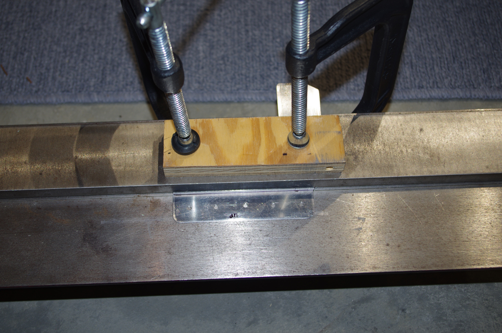
 A sheet metal bending brake formed another bracket for between the rib and the pitot mast backing plate. The right photo shows the bracket clamped prior to drilling through the rib.
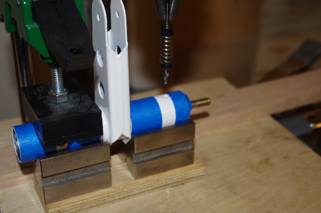
 Here the #8 screw nut plates are attached to the pitot mast.

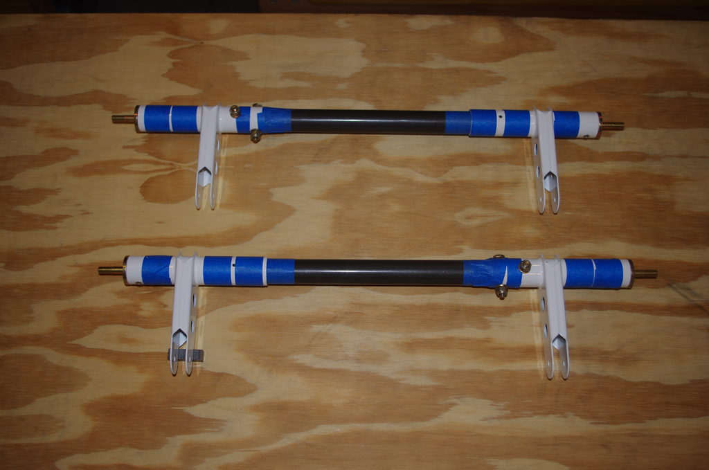
 Two different views of the pitot mast – clecoed in the final position and showing in relation to the modified skin.
===========
MISCELLANOUS ACTIONS

 Rich visited for two weeks to help with flap gap riveting, inspection port assembly and other miscellaneous activities. We used CherryMax rivets of type CR3212-4-6 countersunk (qty. 6), and CR3213-4-2 (qty. 14) and CR3213-4-3 (qty. 6) round head rivets on the inner flap gap openings of each wing.
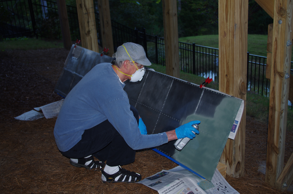
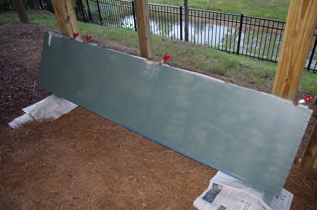 The wing bottoms were treated with SEM Self-etch primer from a rattle can prior to having the inspection port nut plates attached.
===========
AILERON ACTUATION
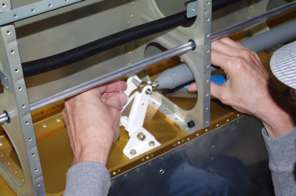 To properly locate the spring attachment points on the aileron push rods, the actuation levers and torque tubes must be installed and the rod oriented in a neutral position. More on that in later posts.
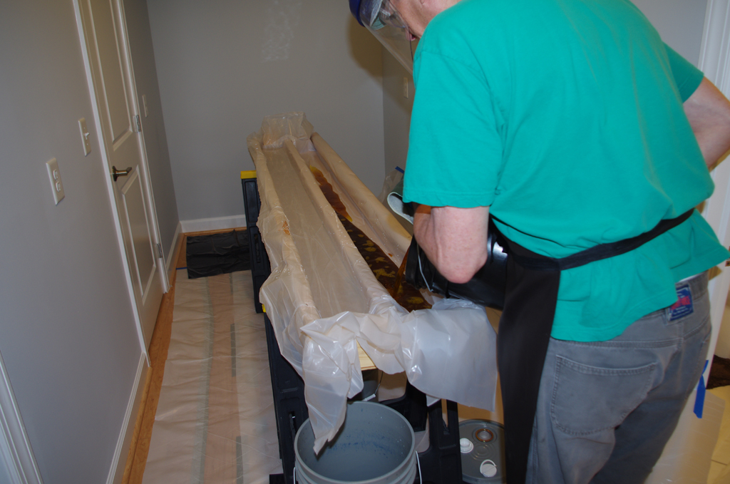

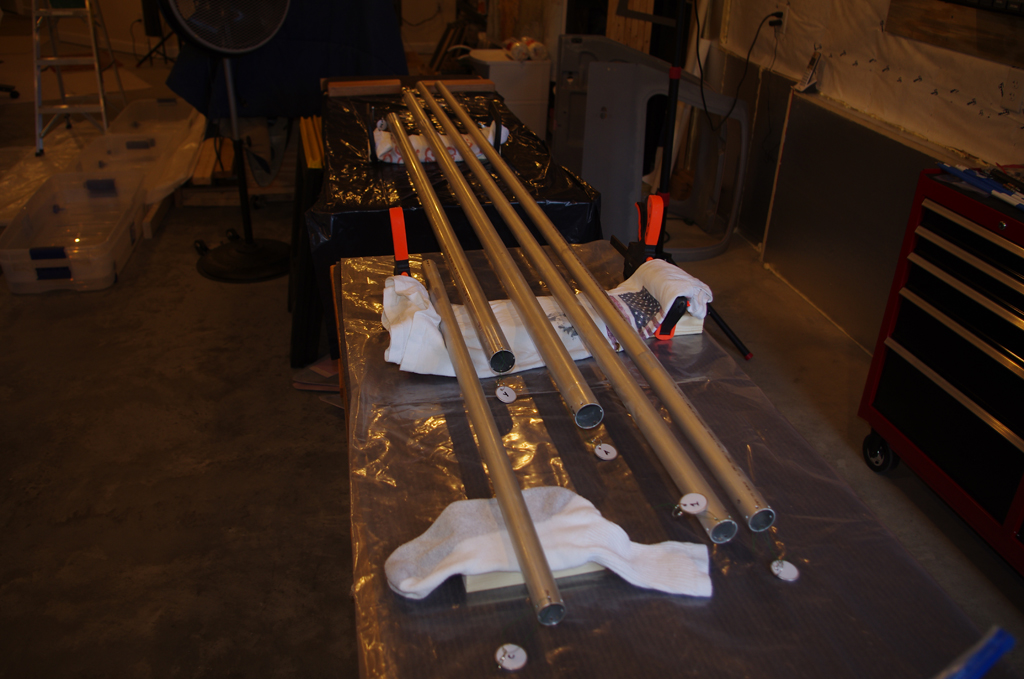
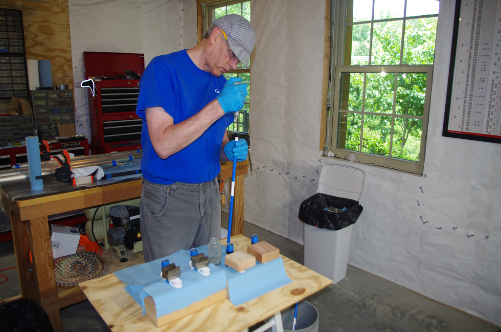
 Priming the interiors of the flap pushrods and torque tubes is recommended in the plans. A small quantity of two part, epoxy primer (PPG DP40LF) was mixed. A small bit of acetone was added to help the primer flow better along the inner walls of these tubes.