The latest steps were in completing elements of the empennage attachment sequence. All the actions were of an interim nature, further posts on all elements will follow.
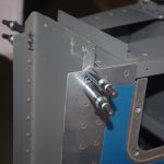
 The last hole in the longeron at the rear of the vertical stabilizer required a nutplate install. The rudder had to be off to access the rivets.
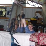
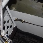 Then install the rudder to test fit the cable linkages. The default lengths in the plans of 1″ on for aft pedal and 2.25″ on the forward pedal did not align the rudder to neutral. Further adjustments were required.
FLAP POSITION SENSOR

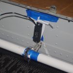 According to literature, many folks recommend using a Ray Allen POS-12 position sensor instead of the default AirWard configuration. A bracket was made earlier for the sensor, then a provisional lever mounted to a 2-piece collar clamp was used to test the throw length and hinge positions.
STATIC LINES

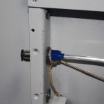 A custom bulkhead configuration of 3/4 rubber grommet, then a push-to-connect pneumatic fitting connected to NPT-AN4 adapter was made for the forward 1/4″ Verstube termination.
The static tube pulled through the cable runs was aluminum instead of plastic. I wanted to ensure this would never require a replacement after the plane is finished.

 A similar fitting configuration was used in the rear for a permanent attachment. A custom mounting bracket uses the existing lighting hole as a pass-through. Standoffs will hold the plastic lines from the external static ports.
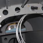
 The aluminum tube was run up the bulkhead rear. It is fastened with 1/4″ diameter Adel clamps and will be terminated at the push-to-connect tee.
 The final configuration still needs to be tested with soapy water for minor leaks. However, once tested, the ‘home run’ of aluminum tube through the mid-fuselage should never require additional maintenance (at least that is the intention).
EMPENNAGE FAIRING
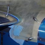 Finally the gaps between the raw empennage fairing and the horizontal stabilizer were removed with SuperFil.
