Category Archives: Section 43, Cabin Cover

Transparencies and Miscellaneous

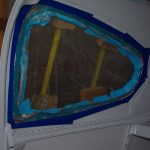
The Lexan/Plexiglass transparencies used for the rear and door windows were bonded with Lord 7475A/D two-part epoxy adhesive.  These parts were trimmed to size and smooth sanded in prior posts.
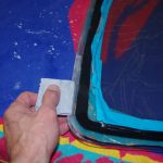
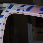
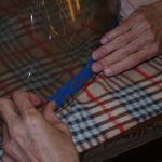
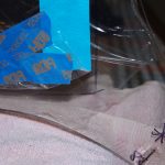
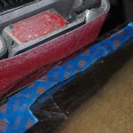
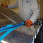
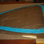
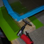
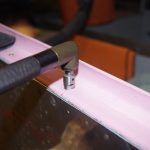
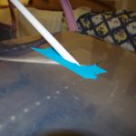
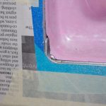
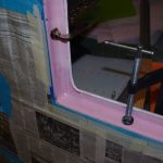
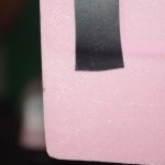
Electrical tape provided protection on the rear windows during roughing the inner surface with 120 grit sandpaper to enhance adhesion.  Then the window frames were taped so excess adhesive could be easily removed.


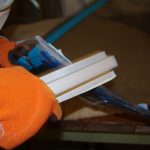
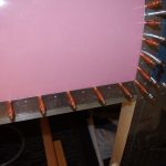
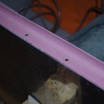
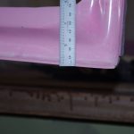
Shims in the form of AN960-10 and AN960-10L washers were placed to bring the window surface to level to -.010 inch of the canopy. This helps with the physical holding of the window, plus will allow for later blending with filler to a smooth transition.

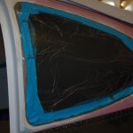


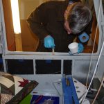
The bonding process was a bit scary – only one shot to get it right.  The reason is the Lord adhesive cures very quickly and is extremely difficult to remove after it sets. Fortunately the rear windows turned out fine.
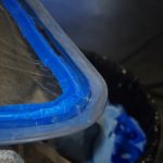
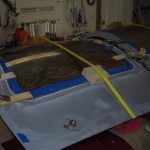


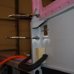
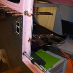
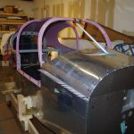
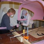
The same method described above was used on the door windows.  Straps and clamps hold the windows tight to the frame while the adhesive cures.


GMU MOUNT BRACKET

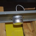
Previously a mounting bracket for the Garmin GMU 22 magnetometer was fabricated for placement in the mid-tail section. The angle of the bracket should be as close to zero degrees level with the fuselage waterline during flight as possible.  It was determined with a digital protractor that the bracket needed to be adjusted about 1.8 degrees down to meet this requirement.

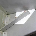
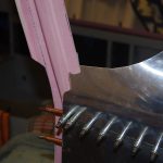
The bracket was constructed so that brass screws adjust the tilt angle of the magnetometer platform to the flight waterline.  More on that adjustment in a later post. Here the GMU bracket is positioned along the plane centerline

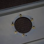


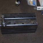
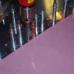
The GMU bracket seen from above and below after priming from the hole drilling.  Note the use of brass screws and stop nuts.  According to vendor specifications, any magnetic components should be at least 2-3 feet from the magnetometer. The location of the bracket in the tail should achieve this goal.


These pictures are the final fit of the GMU bracket to the custom platform.


Canopy, Doors, and Custom Parts

Work has continued on plane parts, though the frequency of my posts has diminished since the beginning of the year.  Here is a quick catch-up of recent activities.

The fuselage sill is filled with two-part resin/colloidal silica mixture just prior to dropping the canopy into place.


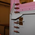
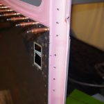
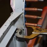
The lower retaining screws are locked into position while the resin cures.  Next the canopy and mid-skins are pop riveted together along both sides.  These two actions permanently attach the canopy to the fuselage.


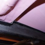
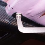
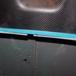
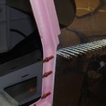
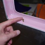
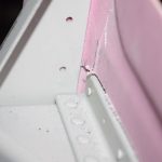
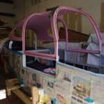
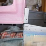
Here are exterior and interior views of where the canopy and mid-skin meet. Overall a nice result.


DOOR HINGE PIN BLOCKS

The PlaneAround center cam gear block is located under the gear mechanism and then drilled/screwed in tightly.


Next the door pins are replaced with custom turned 5/16″ bolts to indicate the exact locations of the bulkhead through-holes.  The right photo shows the resulting latch pin location.


Finally the outer pin blocks are positioned to force the door down and in when the door lever is activated. Right now the fit is very snug, but I expect this will loosen a bit over time.  One this is for sure with this configuration, those doors will not be coming off the airplane in flight!


Baggage Door Hinges

I was not happy with fit or configuration of the original baggage door, so off came the larger hinges.  These were replaced with smaller hinges, and pins moved to a middle insertion point.  This allowed the relationship between the door, hinge and outer skin surface to be flush, as compared to having the hinges sticking out to allow pin insertion.


Custom Parts

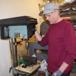
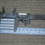
Moving heavy objects around in the basement shop will be helped with a few custom-made skates.  These are made from 2×4 steel beams, 5/8″ drill rod at 10-2RS sealed ball bearings.  The plans are from the internet with no welding required, just proper alignment in the drill press. Eric will make 3D printed end caps to hold the skate axles in place.

Overhead Console (1)

The Christmas vacation provided opportunity for some significant shop time.  The main focus for the 10 days off was fitting the overhead console and fabricating the rear seat backs.

The carbon fiber console was obtained from AeroSport Products. It is very light weight, but not exactly proportioned to the Van’s cabin cover.


The middle portion needs to be relieved to accommodate the heavy fiberglass reinforcement section of the cabin cover.  This element apparently is very significant to the structural integrity of the plane and everyone suggests no alterations to this element should be undertaken.  My intention is feather the console into the ceiling with fiberglass and paint (no need for the carbon fiber look).


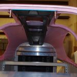
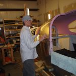
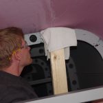
Here are photos of aligning the rear console with the baggage bulkhead.


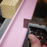
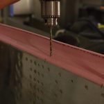
A #30 drill with a drill stop set to a depth of about 1/4″ was used to drill through the carbon fiber and the under layer of fiberglass/resin of the cabin cover – just enough for a cleco to grab. Drilling much further would penetrate the outer fiberglass, definitely not recommended.


The console was removed and modified for the center bracket, then refit to check clearance.


Here the console is shown in final fit configuration.  Further work on vents, lights and cabling will be performed with the cabin off the plane.  With the canopy upside-down gravity will assist holding the console in-place.


Cabin Cover (5)

This week was about finishing the rear windows and starting on the windscreen.

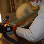
The  process for the rear windows is about first getting close to the scribe line with a Dremel tool. Then using 120 grit sanding belt before hand shaving closer with 220 and polishing/rounding the edges with 320 grit.


For the windscreen first peel back the protective covering just enough to expose the previously marked scribe line.


The windscreen is a slightly different process, as it is much thicker (roughly 1/4″ Lexan or acrylic).  My technical counselor advised against using a Dremel tool, saw or other cutting mechanisms (tend to cause cracking in this type/thickness material).  Instead a 3″ belt sander with 80 grit paper is used to get close. Everything else is by hand.


When talking about ‘by hand’, I mean hours of edge sanding with 80 grit paper on a Great Planes sanding block. Going through Lexan this thick takes time. Check for fit, mark the high spots, and repeat over, and over, and over…


The hand shaping process requires many iterations, but this way has less danger of removing too much, too fast in the wrong places as with power tools.  The final outcome is coming into shape nicely.  More of the same fitting process this weekend before the edge polishing can begin.

Cabin Cover (4)

Attaching the center console brace and beginning to trim window panes was the order for the day.

imgp7261The center brace is clamped in the middle of the forward canopy cover, then match drilled with a #12 drill to accommodate an AN3 bolt.  This is tightened down to fasten the brace, so the the rest of the holes can be drilled.


imgp7263Here is how the top of the outer cabin cover looks after the fastener holes are completed.


Here are left/right pictures of the bottom portion of the center brace attached near the firewall.  Two AN3 bolt hole are drilled between an angle bulkhead and a reinforcing plate.


imgp7274A set of spacers 1-13/32″ long  are fabricated from 5/16″ diameter tube.  This will eventually be driven into enlarged holes for the center brace.  The cabin cover needs to come off for further processing, so this step will be saved for later.


imgp7265The plans call for fitting the windscreen first, but I wanted some experience dealing with Lexan/acrylic trimming beforehand.  The side windows will be my test platform – if things go south these will be cheaper and easier to replace compared to the windscreen.


imgp7275imgp7276Pull back the protective covering and get ready to power trim!

Cabin Cover (3)

Over the Thanksgiving week off the focus was finishing major elements of the cabin cover.

imgp7192The first step was complete match drilling the mid-skins to the cabin cover.


imgp7191imgp7194Next was clamp the rear door frames to the bulkheads and match drill for #10 countersunk screws.


imgp7200imgp7198Here the right side has been drilled and clecoed into place.


imgp7206Now for the forward door frames. The gusset  is clecoed to the bulkhead, but match drilling for the #10 screws to the fiberglass frame goes through about 1/4″ of empty space. According to the plans, this space will have structural filler applied.


imgp7226

imgp7225Getting the fiberglass trimmed for the front deck took quite some time. (between initial Dremel tool sanding and hand filing).


imgp7211imgp7216Next was measure the door jam bottom, then drill #19 holes for #8 countersunk screws.


imgp7254imgp7257Check for size, then countersink with an angle tool.


imgp7258The final product looks pretty good.


imgp7221imgp7220Now rough fit the center console brace.  Overall starting to look like an airplane.


Cabin Cover (2)

I had another forced pause from the shop due to business travel overseas.  This weekend was getting back in action with Eric’s help on further cutting, fitting and sanding the fiberglass cabin cover.

imgp7098The door bottom needs extensive trimming to get to the proper thickness.


imgp7099Left and right sides need to be notched to accommodate the bulkhead reinforcements at the bottom.  Notice the degree of relief needed to make this fit.
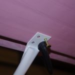


imgp7102The inner section must line up just right with the mid-skin longerons.  Too much taken off will decrease strength for the connecting rivets.  Too little and the fiberglass bottoms out on the longeron and fit will not be proper.


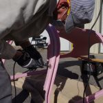
imgp7127First reduction was with a fiberglass cutting wheel on a Dremel tool, followed by a belt sander, hand file and finally Great Lakes 22″ sanding block with 120 grit paper.


imgp7105imgp7141Fit, trim and refit is the process here. Getting the cabin cover to slide in without too much material removed takes time and patience.  On the right photo the 3/4″ offset for windshield and doors are being highlighted with a Sharpie.


imgp7143imgp7145Trim the windshield flange…


imgp7151Clamp the rear door pillar and bottom flange in place.  Then start the match drilling of the cabin cover to the top tailcone skin.


imgp7152

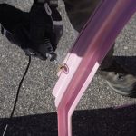
imgp7153Eric pushes up on the cabin cover fiberglass while I drill #30 holes down through the tailcone skin. This process will continue on around the whole baggage bulkhead area.

Cabin Cover (1)

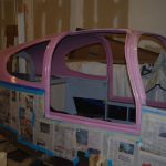
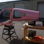
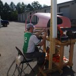
The weather forecast called for beautiful skies and temperatures over the weekend, so I enlisted Eric’s assistance in starting to trim and fit the cabin cover to the fuselage. The idea is get everything aligned properly, then finish the interior metal painting.  This way scratches produced during the fitting process will be reduced.

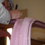
imgp7040Faint scribe lines are on the fiberglass mold from the factory, but difficult to see under most conditions.  I added electrical tape along the edge for a better visual reference when rough cutting with a Dremel tool.


imgp7043imgp7047The process is easy, but takes time.  Rough cut near the scribe line, then hand sand until smooth.  Then fit on the plane and continue sanding until everything lines up perfectly.


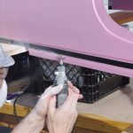
imgp7051Here is a closer look at the rough out process.


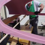
imgp7052A long wooden dowel is attached to a 22″ Great Planes sanding block.  Eric guides the dowel along the opposite end while I smooth sand and get closer to the the scribe line.  The dowel extension will approximately make the surfaces parallel on both sides.


imgp7055imgp7057The first rough fit shows additional material needs to be removed. Sand and refit until alignment is correct.