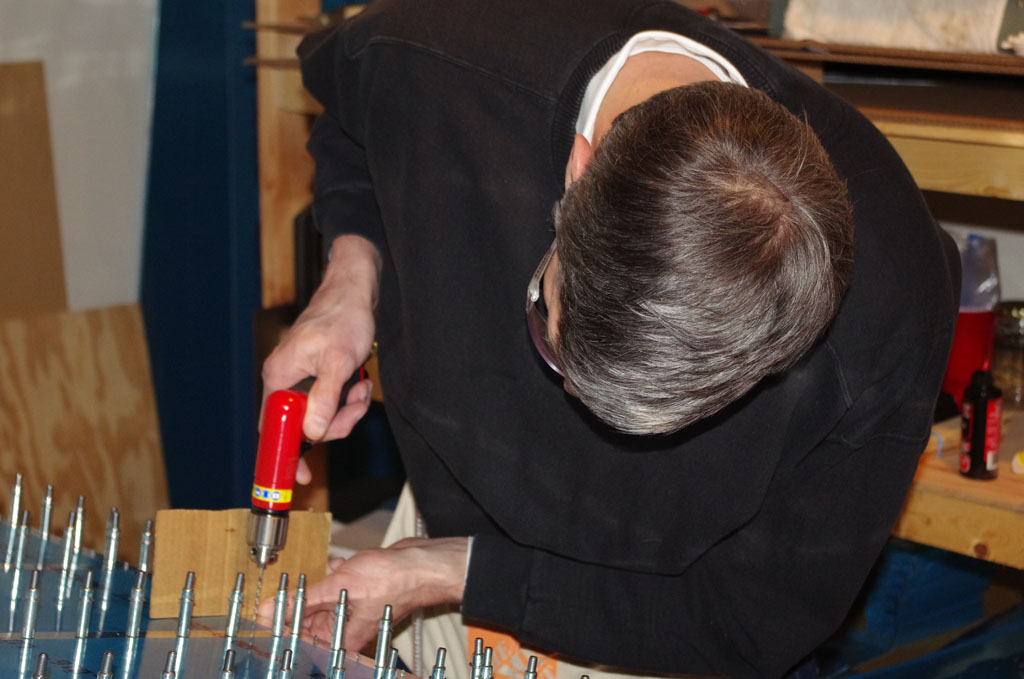
I performed my first modification to the plans today by drilling attachment holes for the static wicks. Based on the manufacturer suggestions , they should be placed on the outer edges and most rear portions of the plane to properly dissipate an electrical charge. Using a pair about 12 inches apart is also recommended. The rudder on the RV10 has two rib stiffeners at the top almost exactly configured for this application.
The modification requires measuring, drilling and countersinking holes for nut plates to secure the static wicks. There are special jigs available for different sized screws, so I bought one (~$35) for 10# screws to fit the Dayton Gardner 16165 wicks. Because the skin and stiffener on the rudder are only a combined .050″ thick, I started the main hole with a #40 drill, then progressively got bigger (#30, #21, #17, #12, #10) until the final hole diameter was reached. This was a bit tedious, but kept the thin skins from bending or tearing. The jig then is used to exactly align the attachment rivet holes. Since holding the wick in place is not considered structural, an ‘oops’ rivet with a smaller than normal manufactured head will be used to keep the countersink small and shallow (more on ‘oops’ rivets in later posts).
The hardware list for the static wicks and bond straps:
MS21078-3 two lug elastic insert anchor nut
MS21080-3 one lug elastic insert anchor nut
MS35207 machine screws (various lengths will be used)
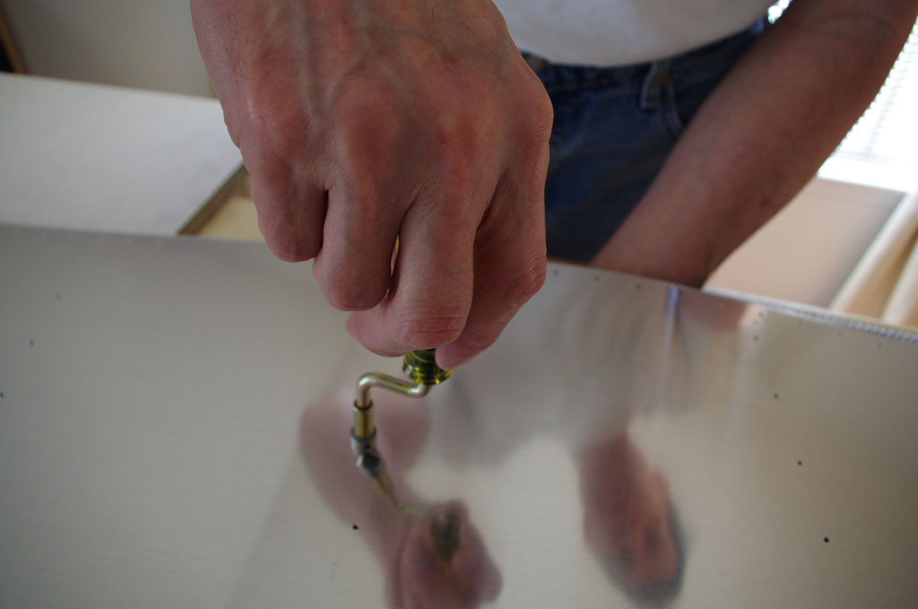
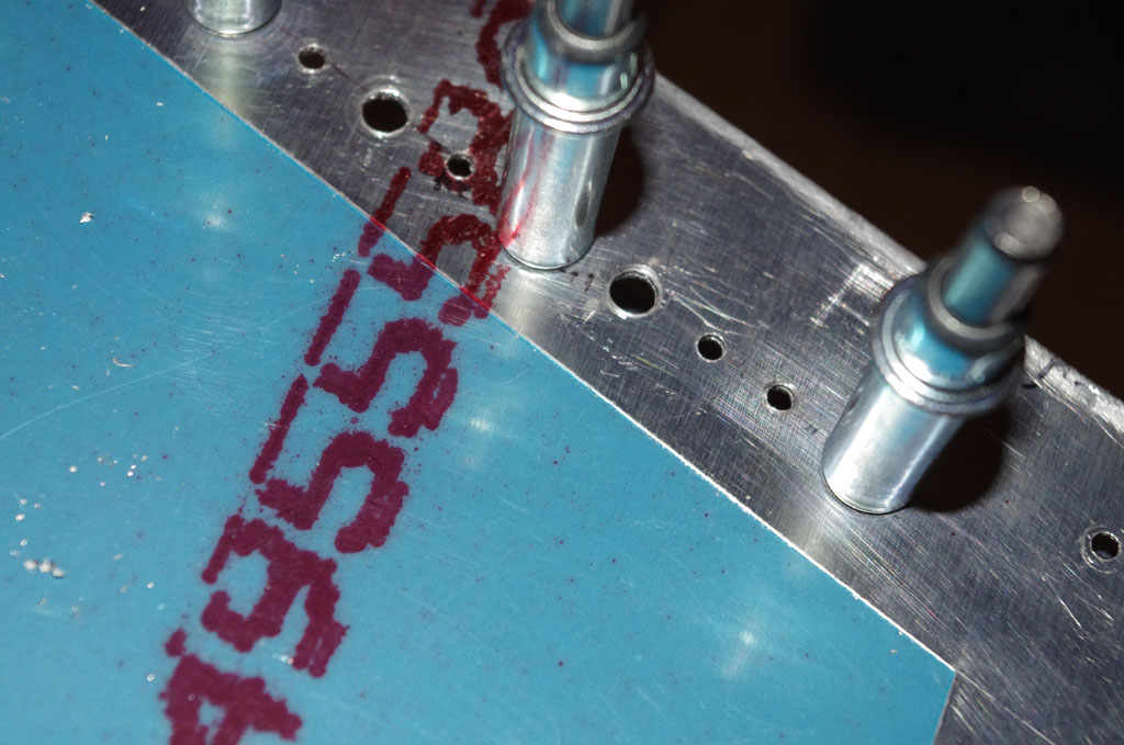
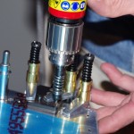 Here using the #10 nut plate jig to position the rivet holes relative to the main screw holes. The jig essentially provides a perfect fit every time. I cannot imagine spacing the three holes properly without that tool.
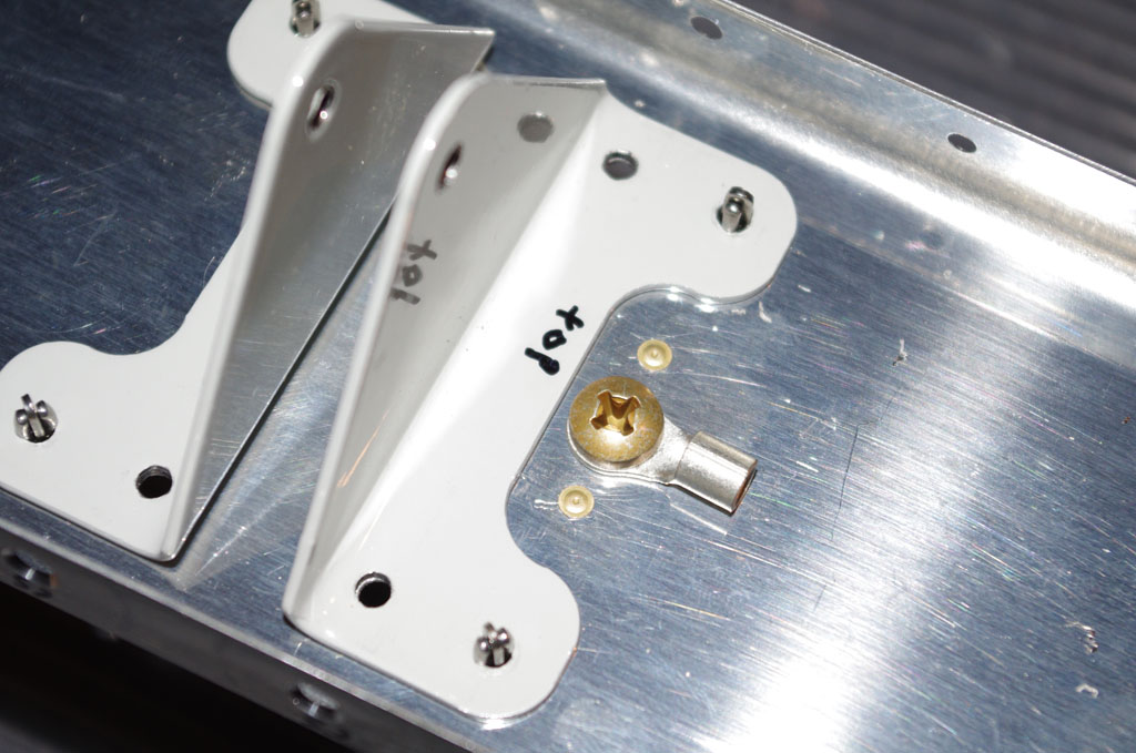
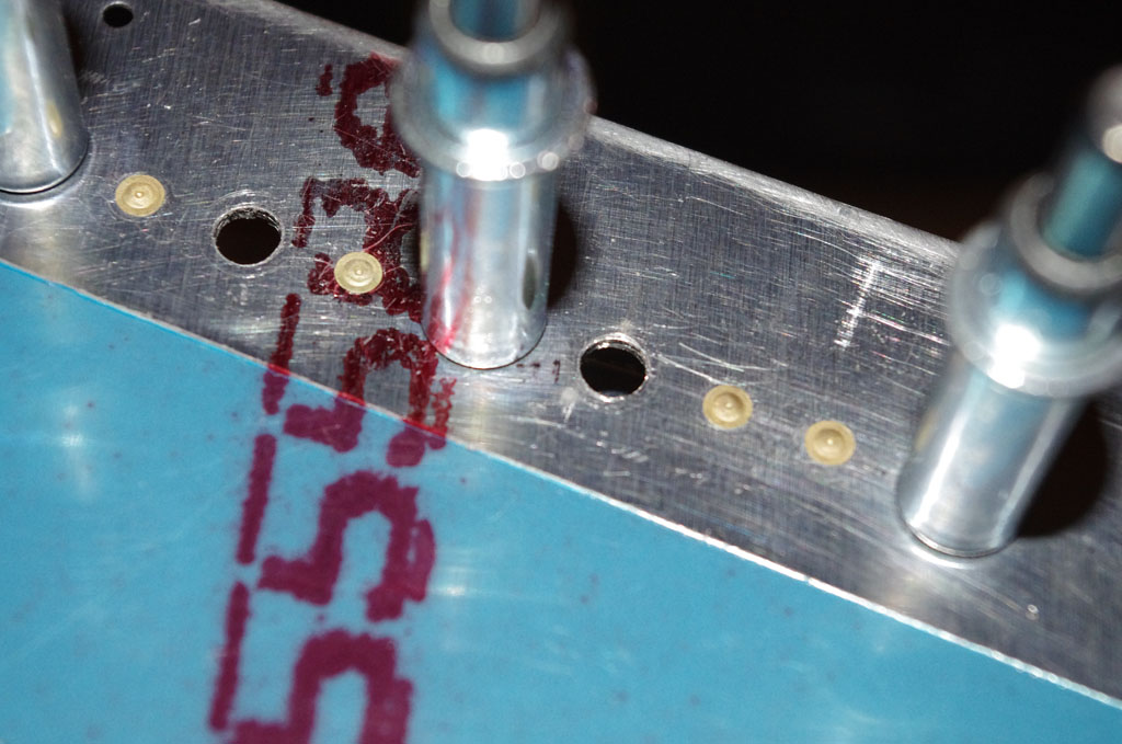
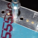
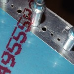 Final drilled holes for the nut plates with plastic inserts. Notice the three hole design on the left compared to the single lobe method on the right.
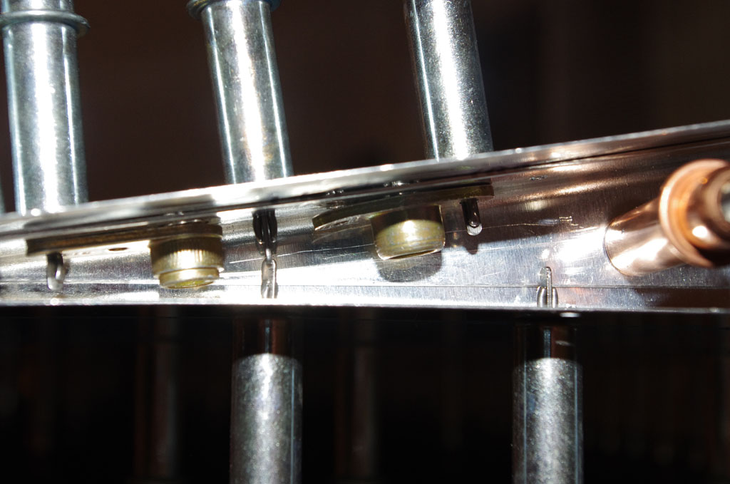
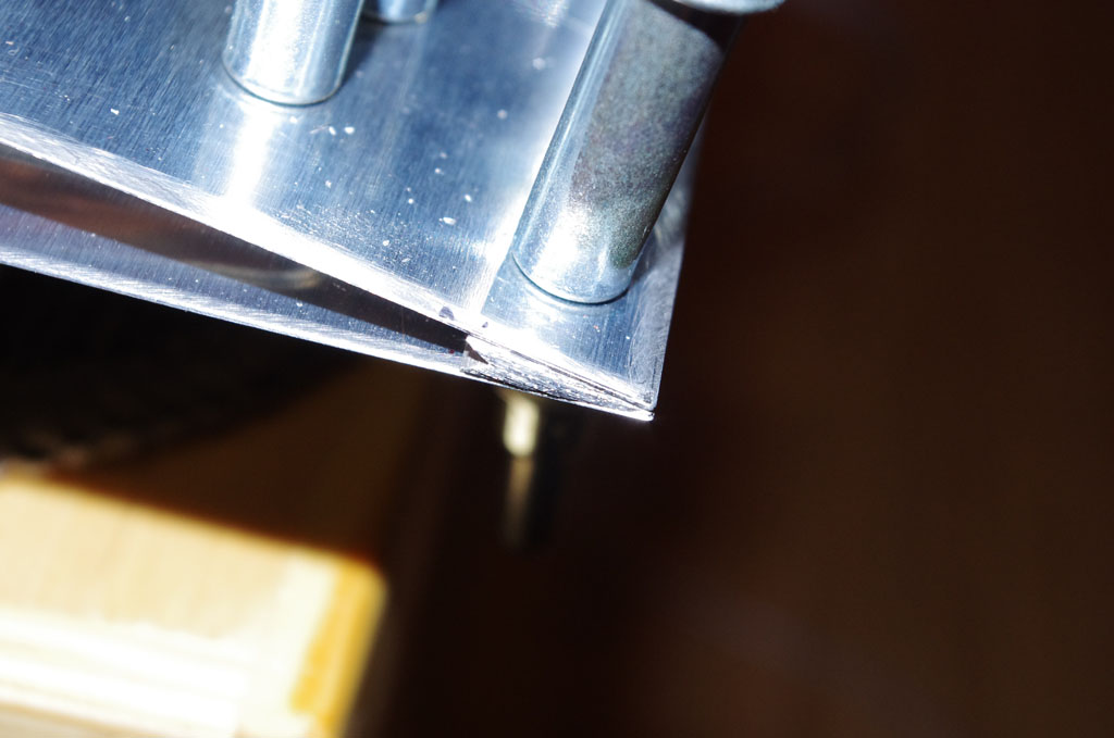
 This picture shows the decreasing headroom moving r-l towards the trailing edge. Notice why the use to the one lug anchor plate is needed here.
 The attached holes have been hand countersunk with an ‘oops’ rivet head used to check depth. This picture shows approximately how it will look when the final riveting is completed.
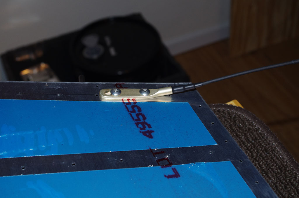
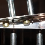
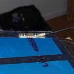 Dry fit of the Dayton Gardner static wick on the uppermost rudder rib. The result looks good.
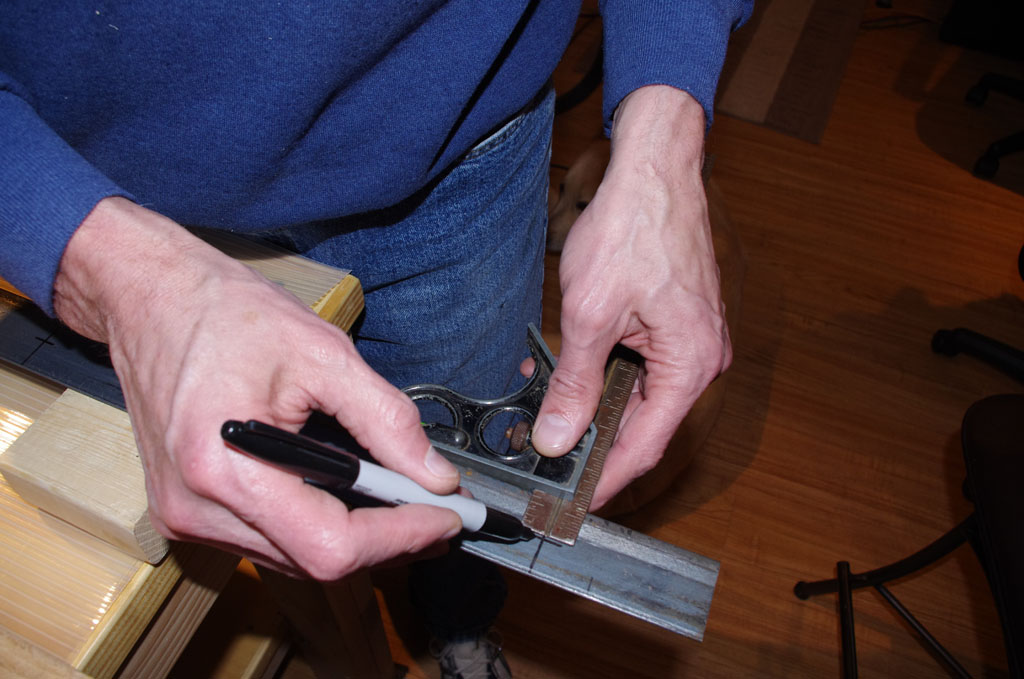
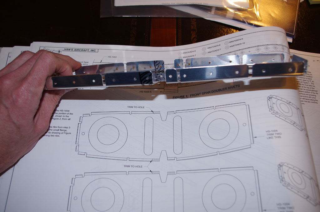 Two of the spar ribs require parts of the tabs to be removed. Here the particular portions are noted with a Sharpie.
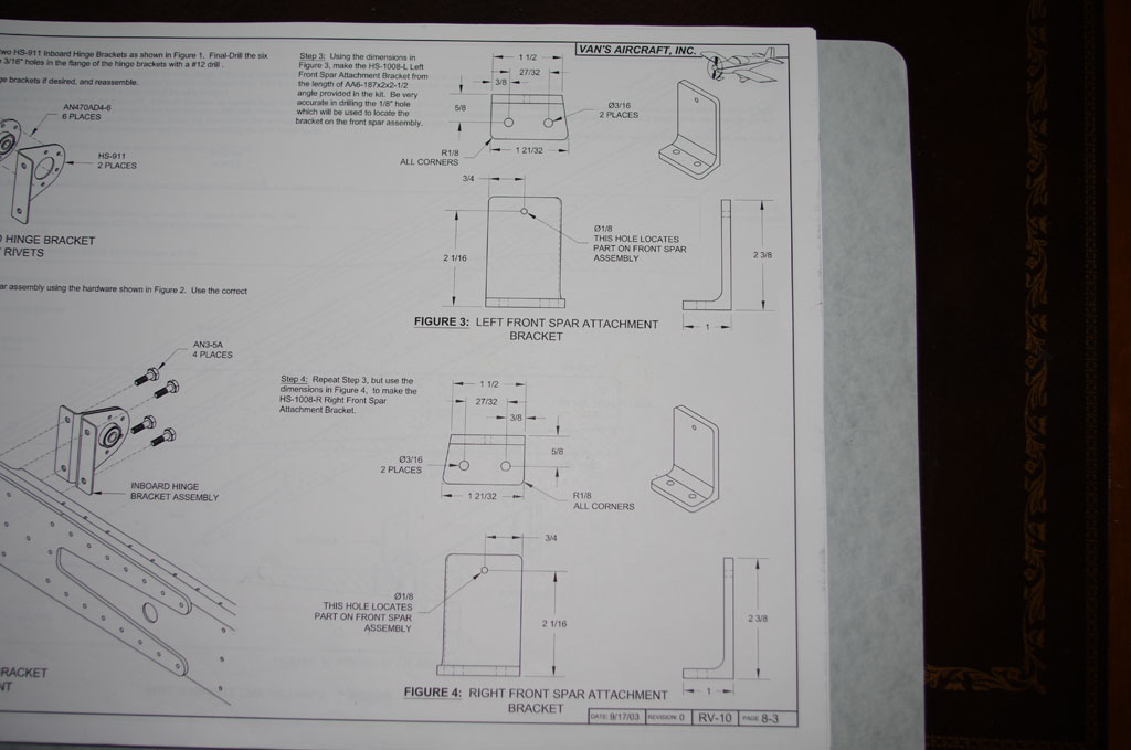 Manufacturing two attachment brackets from 2″ x 2.5″ angle aluminum is going to be a real challenge. I do not have precision equipment to get the holes drilled to the tolerances laid out in the plans. I will probably ask my technical counselor on some much needed advice before moving forward.
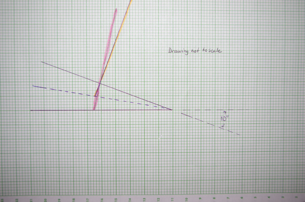
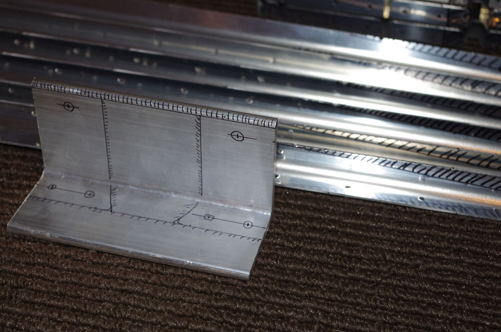 Here is my markup of the angle aluminum used for the attachment brackets.