SB00007 – REV 2 (5-Tools/Techniques)

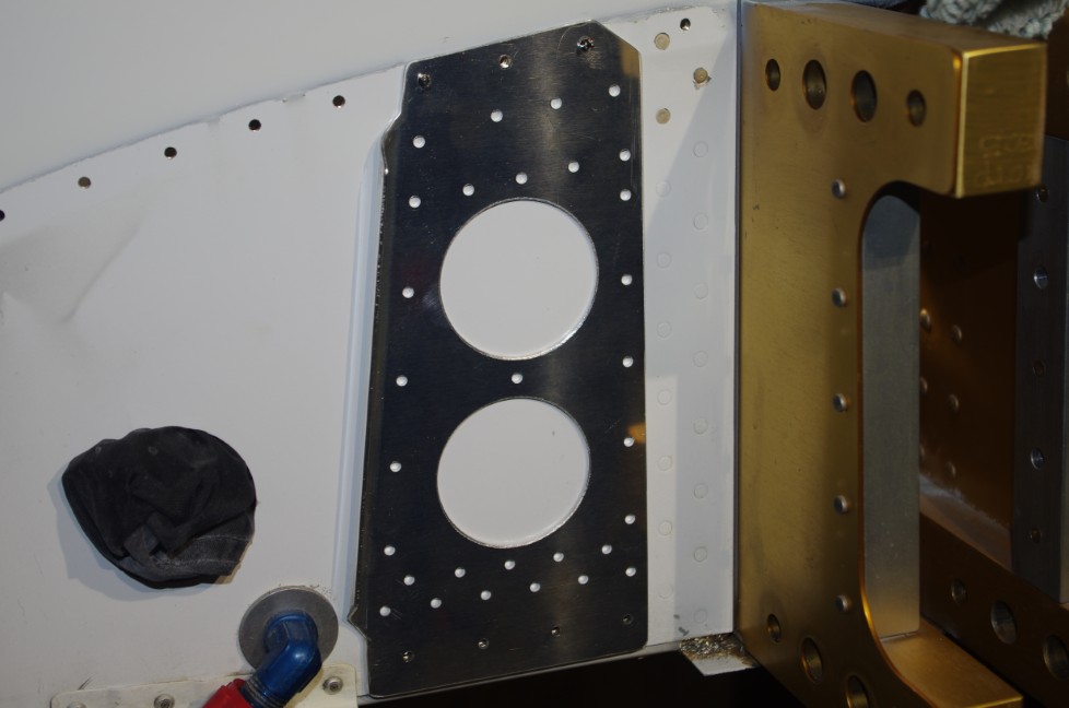
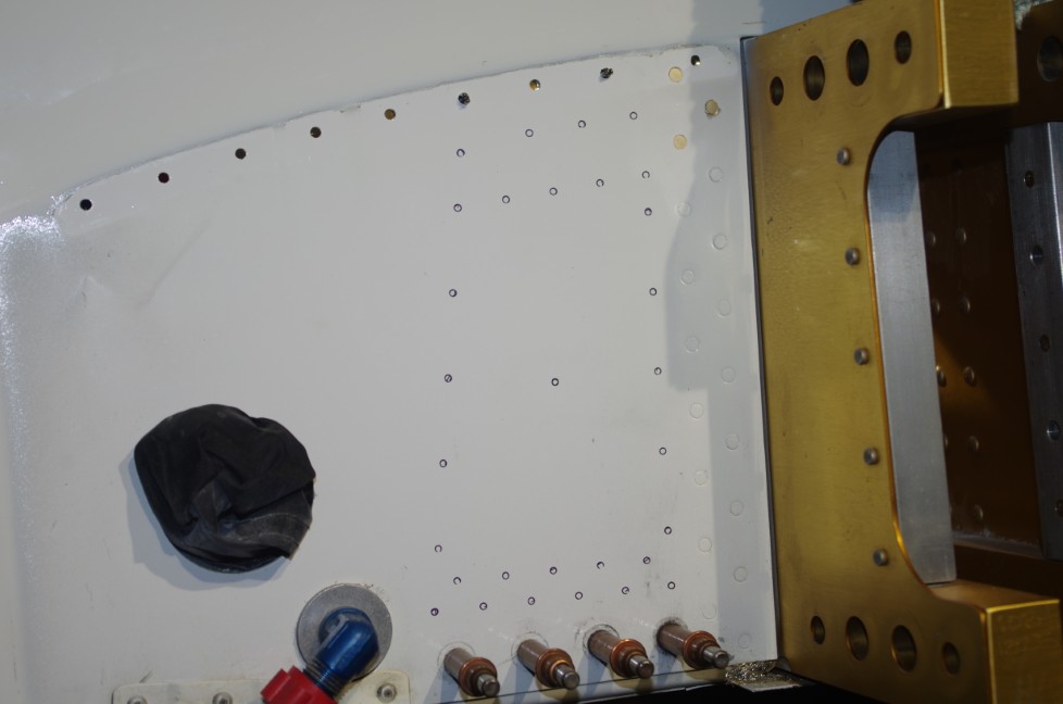
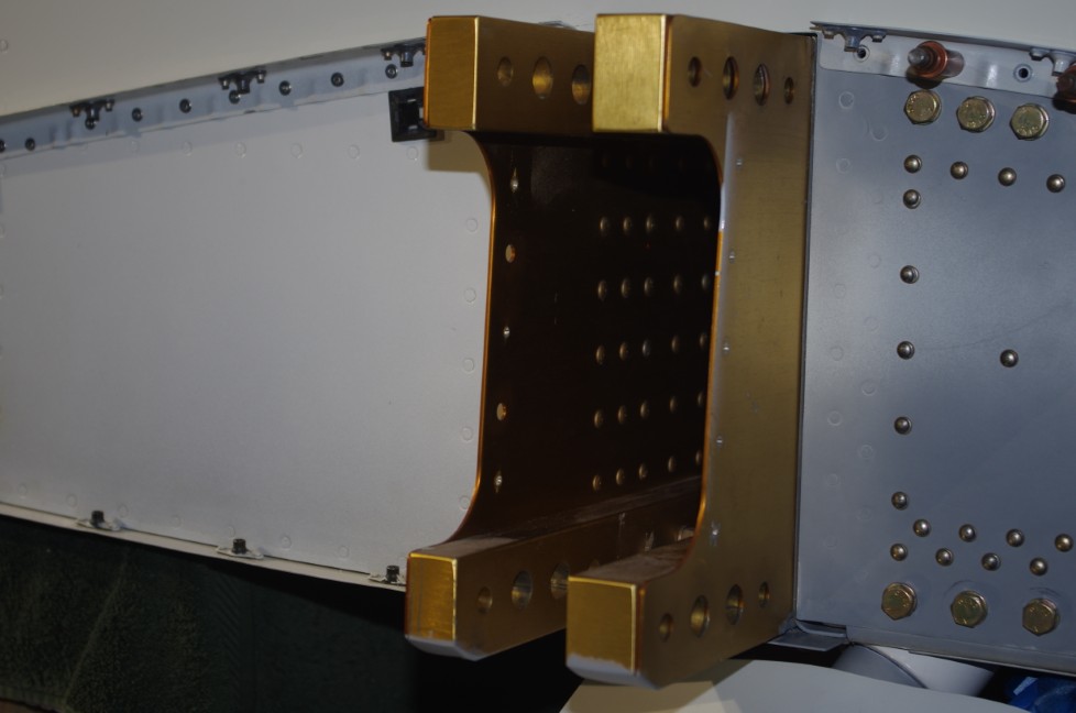
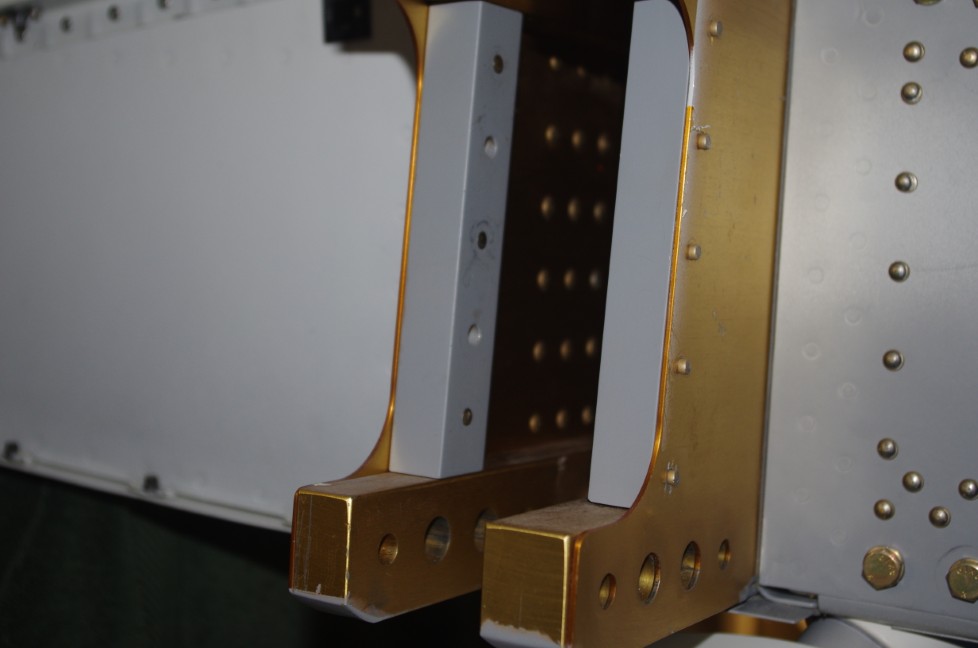
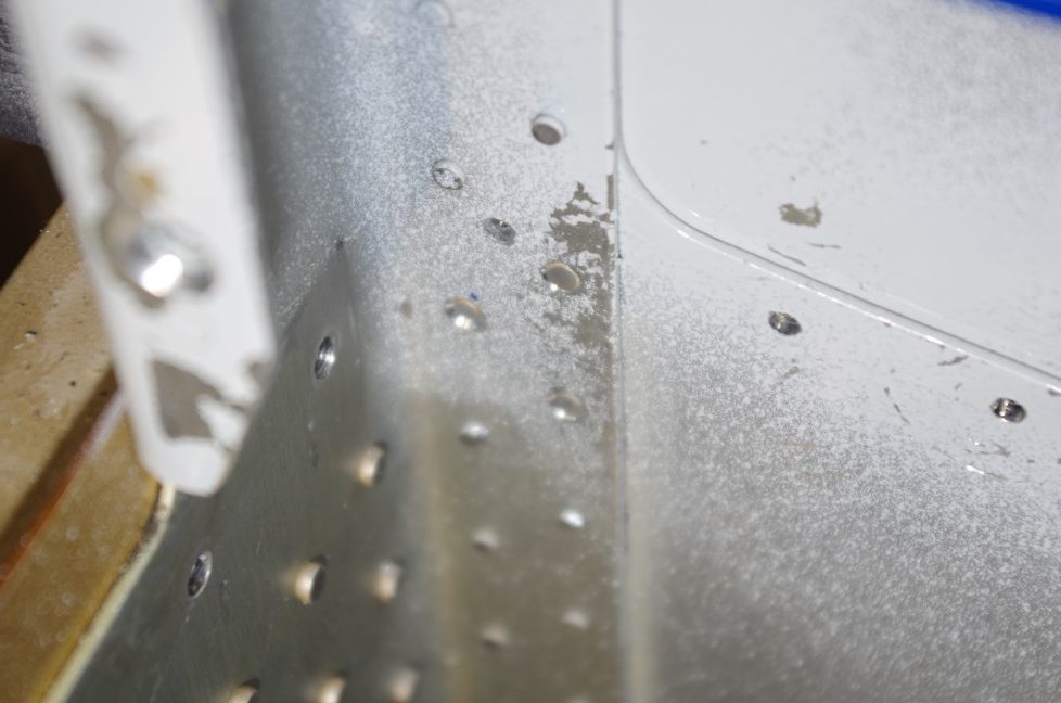
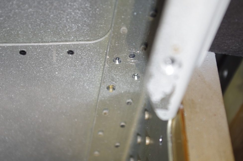
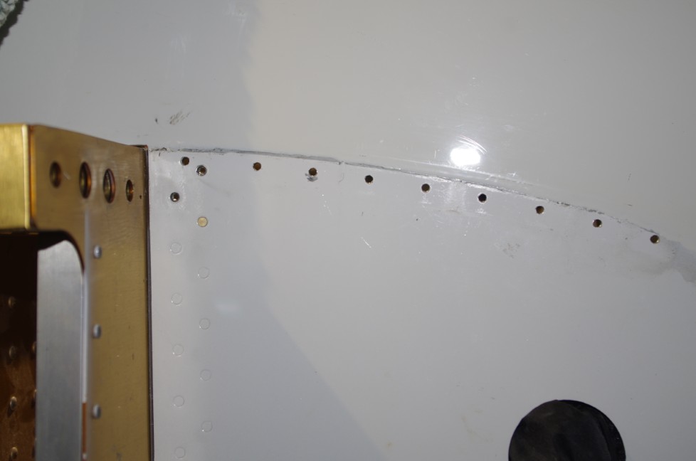
In my opinion enlarging the spar bolt holes to accommodate the new mount was the most difficult part of the entire project.

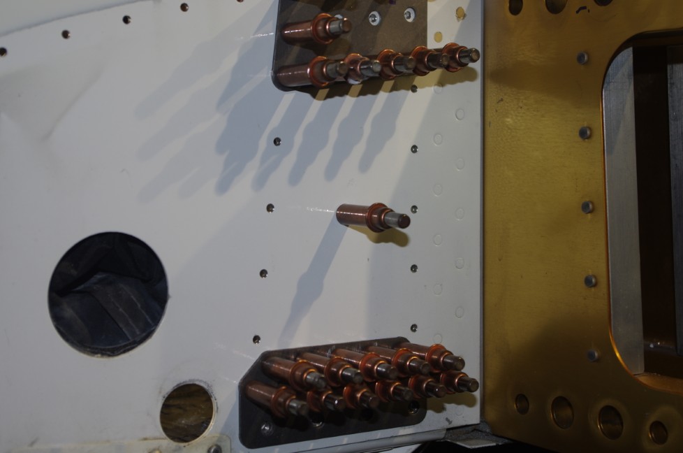
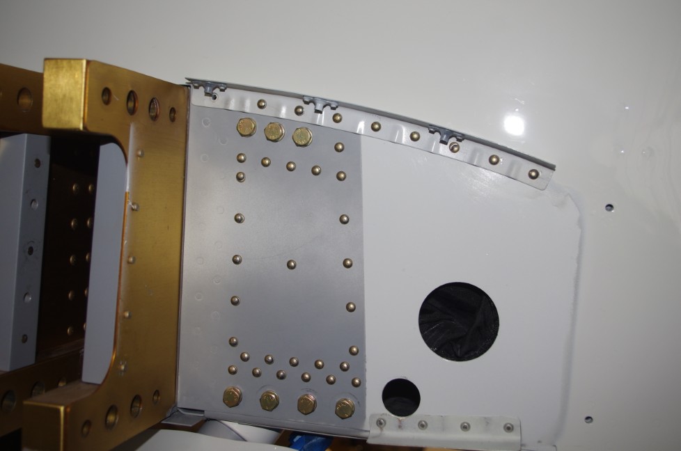
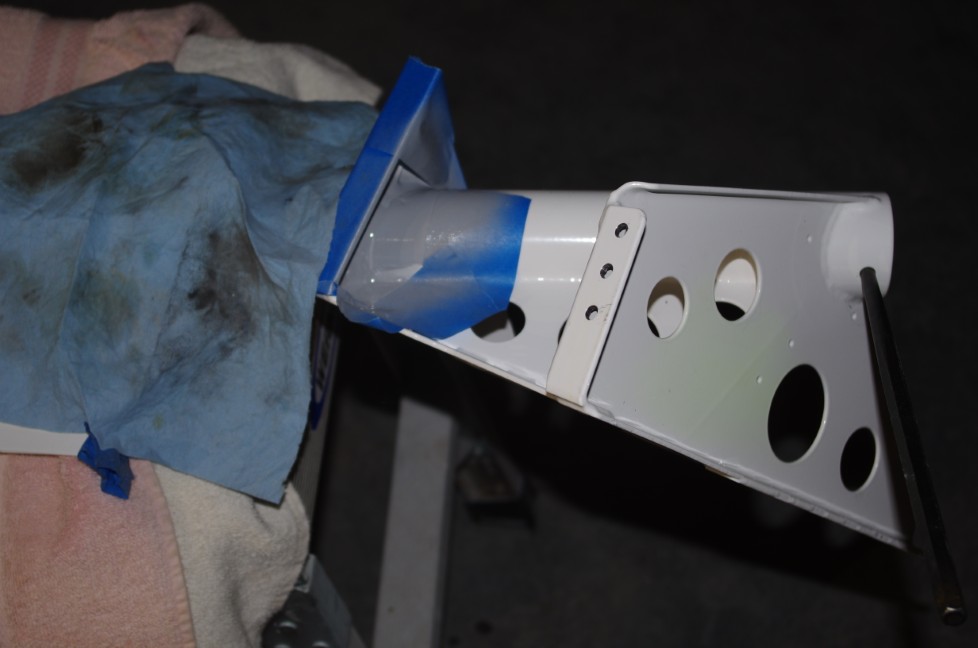
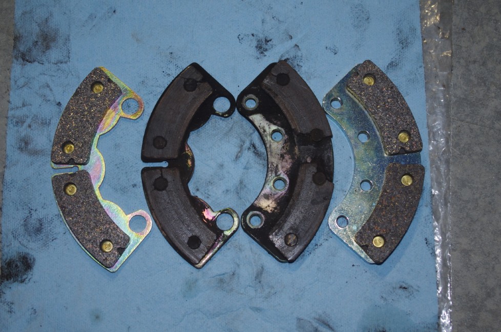
The instructions indicate using the Vans supplied drill guides to final drill the holes to size.  I felt this single pass with a drill may result in an oblong hole, so decided to use another approach.  Custom drill guides made from 1144 stressproof steel hex bar were fabricated on a lathe.  Two drill guides were made for each new hole size – one undersized for initial drilling, and one for reaming to final, nominal size.  Due to restricted space for the lower spar holes, a pneumatic right angle drill was used for the work.

TOOLS (in addition to those described in the Bulletin)

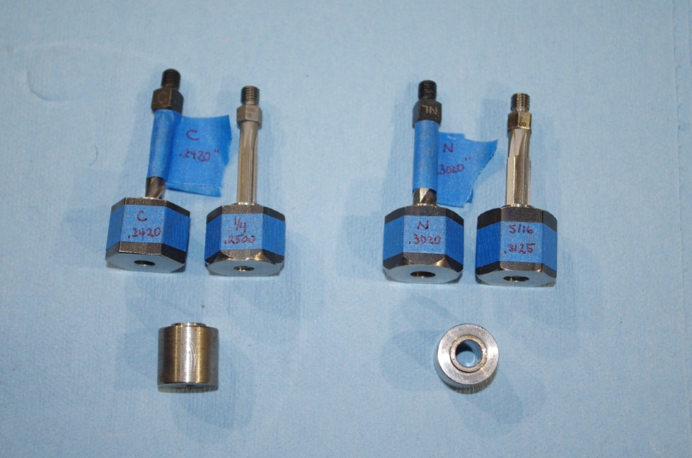
right angle undersized drills and guides (.2420 from C letter drill and .3020 from N letter drill)

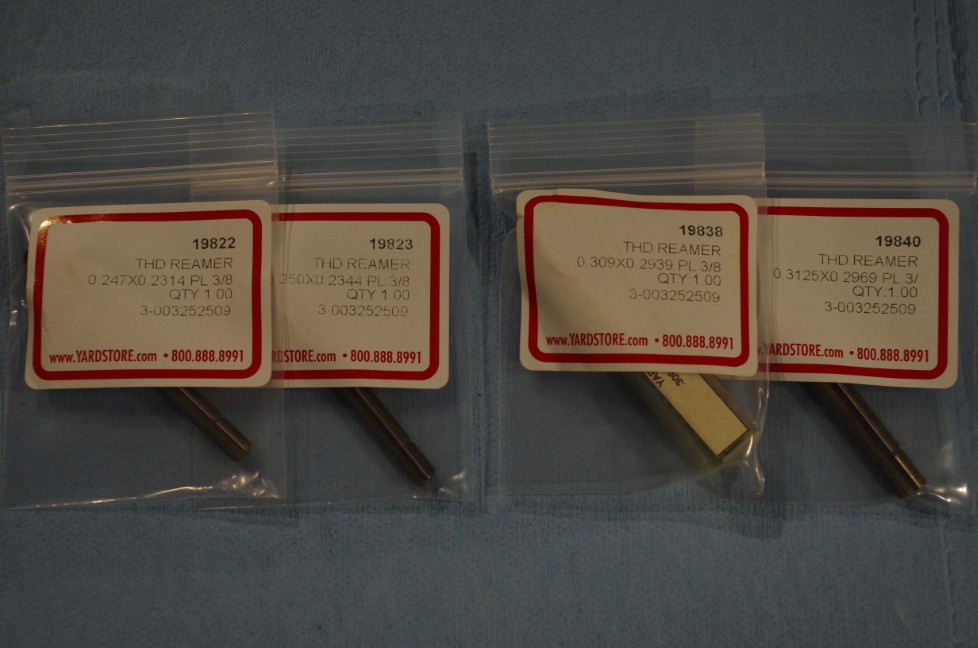
right angle nominal reamers and guides (.2500 for AN4 bolts, .3125 for AN5 bolts)

Yardstore part numbers for various sized  reamers


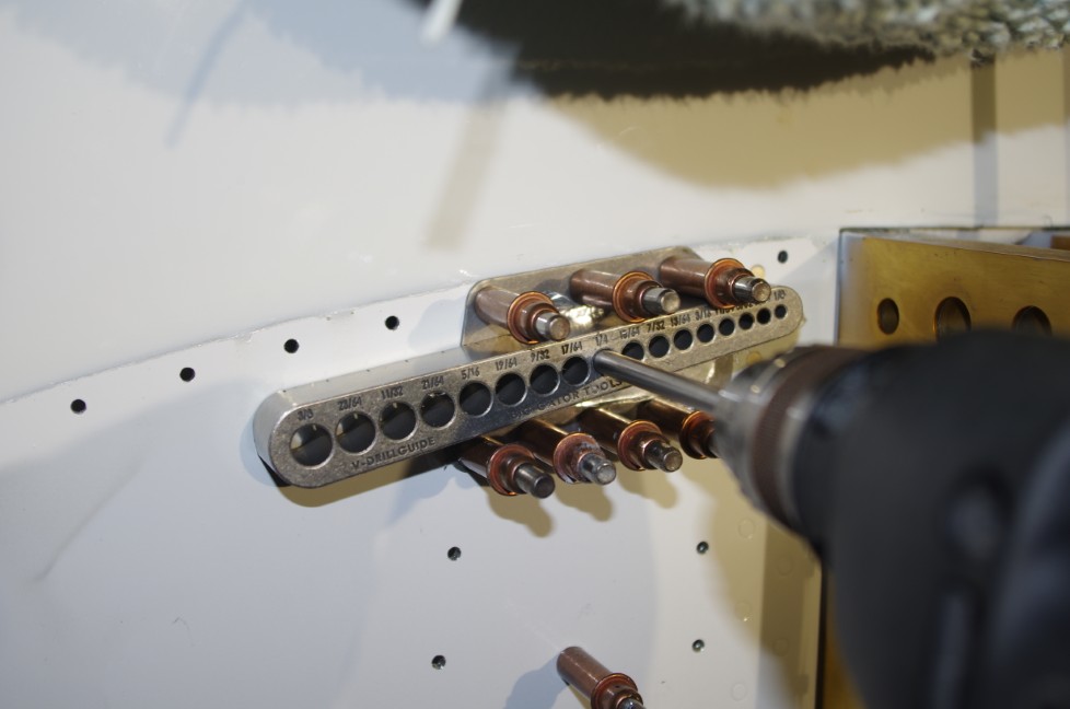
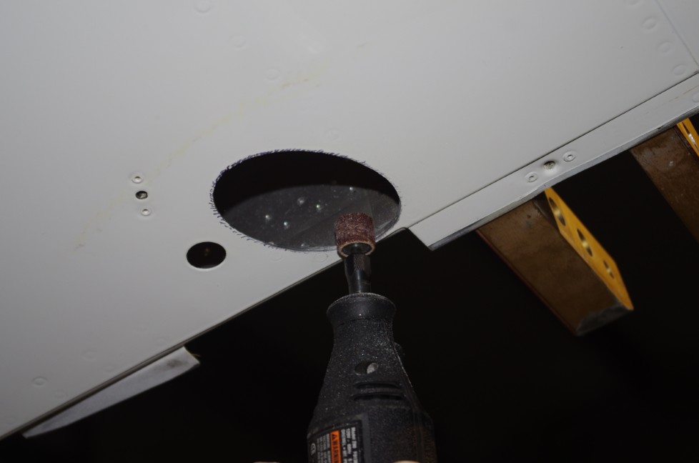
Gator V-DrillGuide for side holes

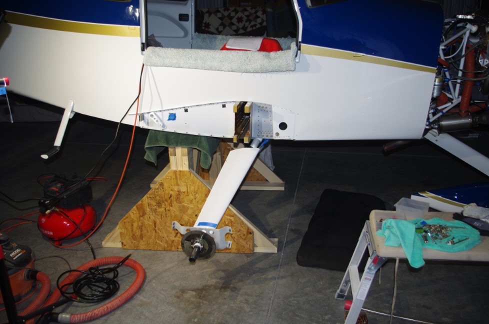
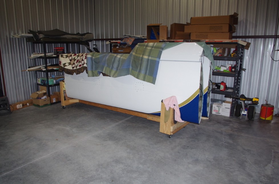
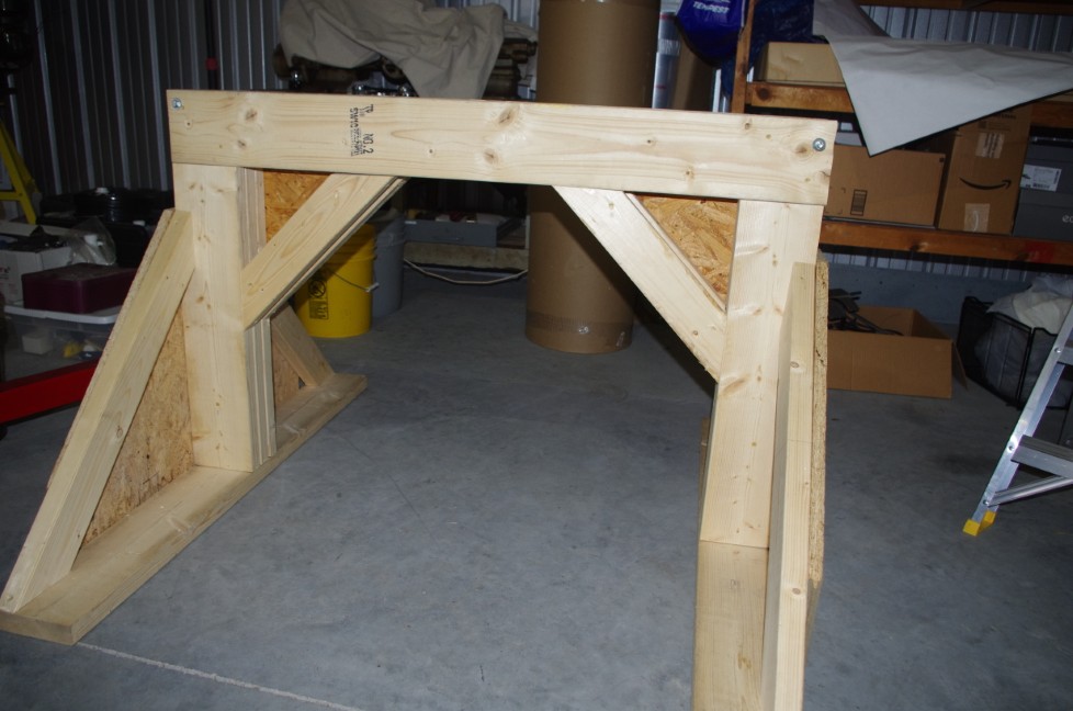
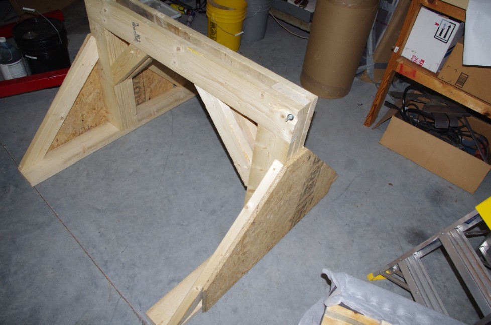
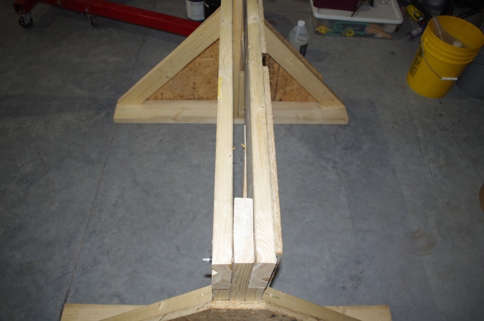
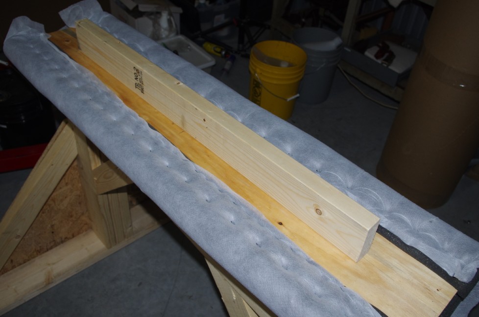
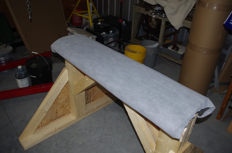
sawhorse for 1600 pounds


TECHNIQUES

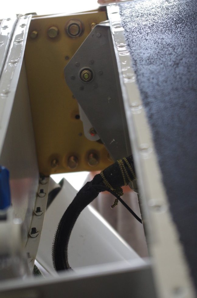
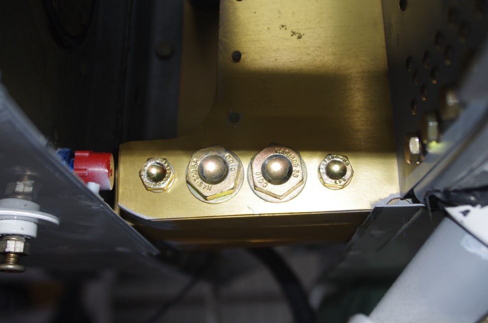
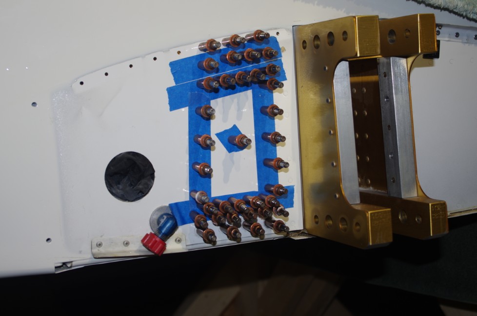
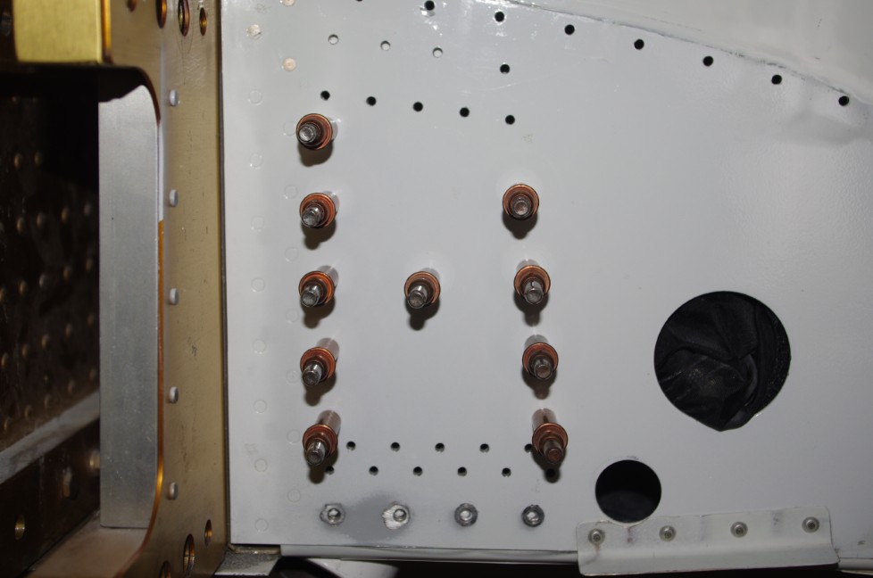
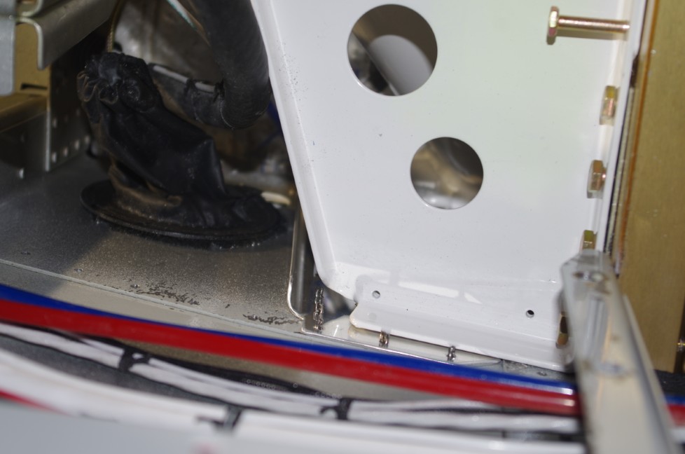
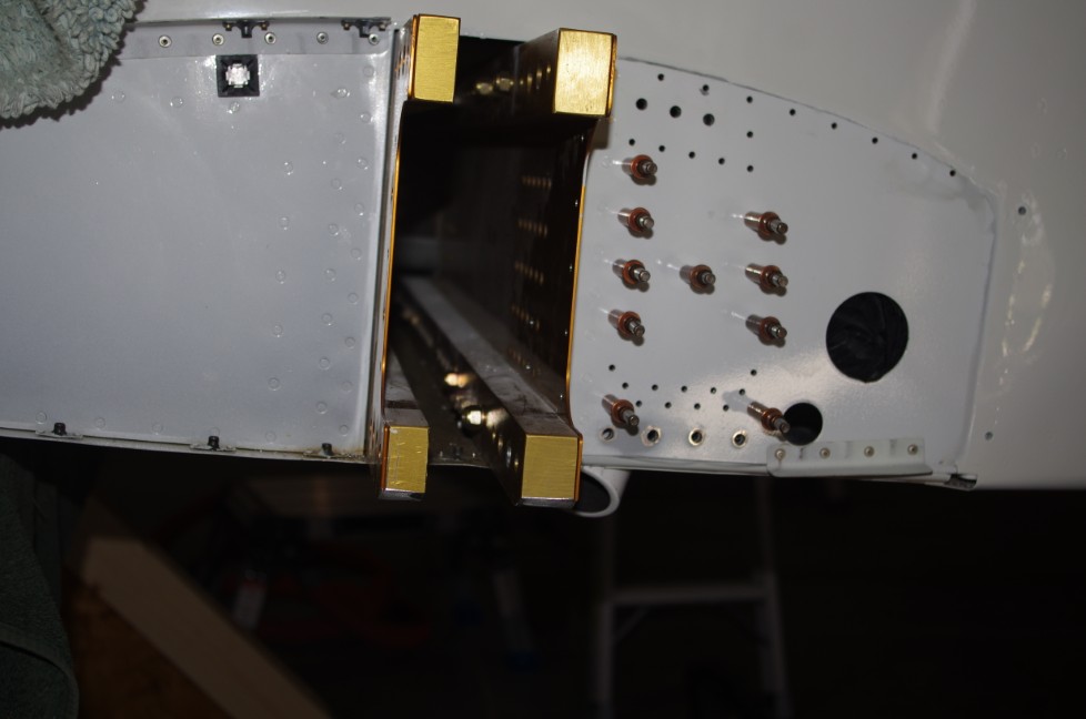
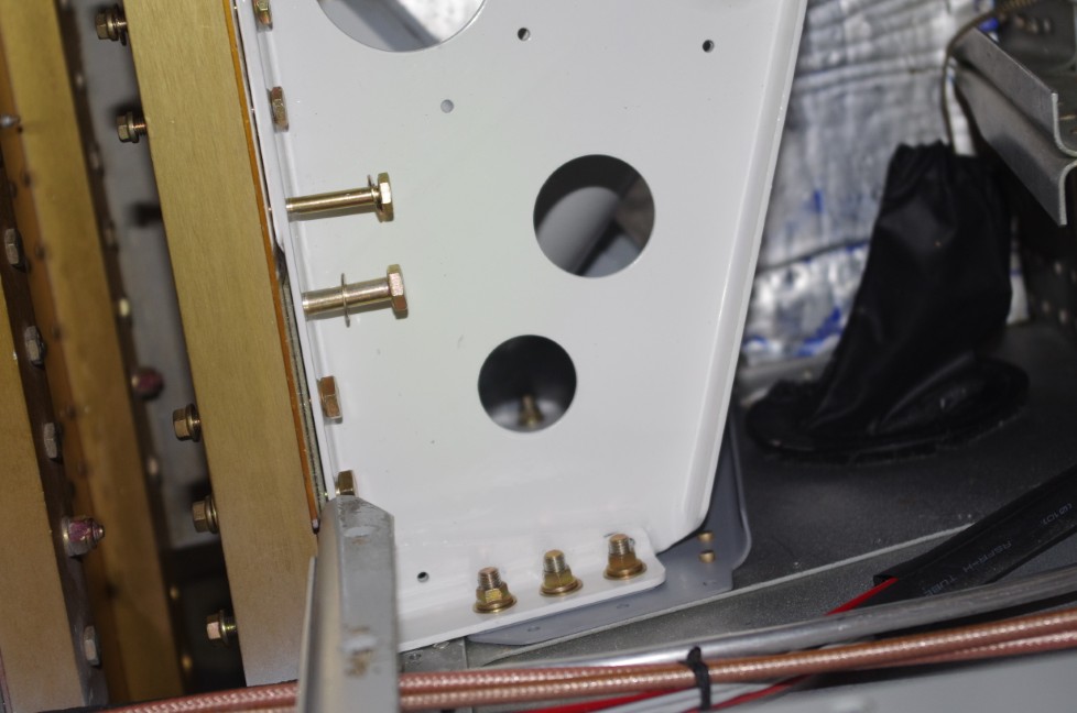
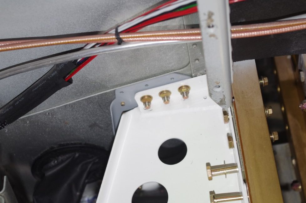
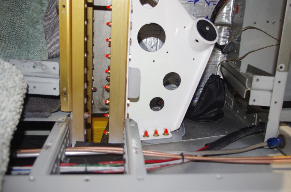
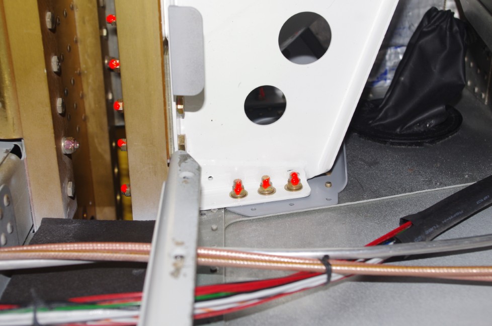
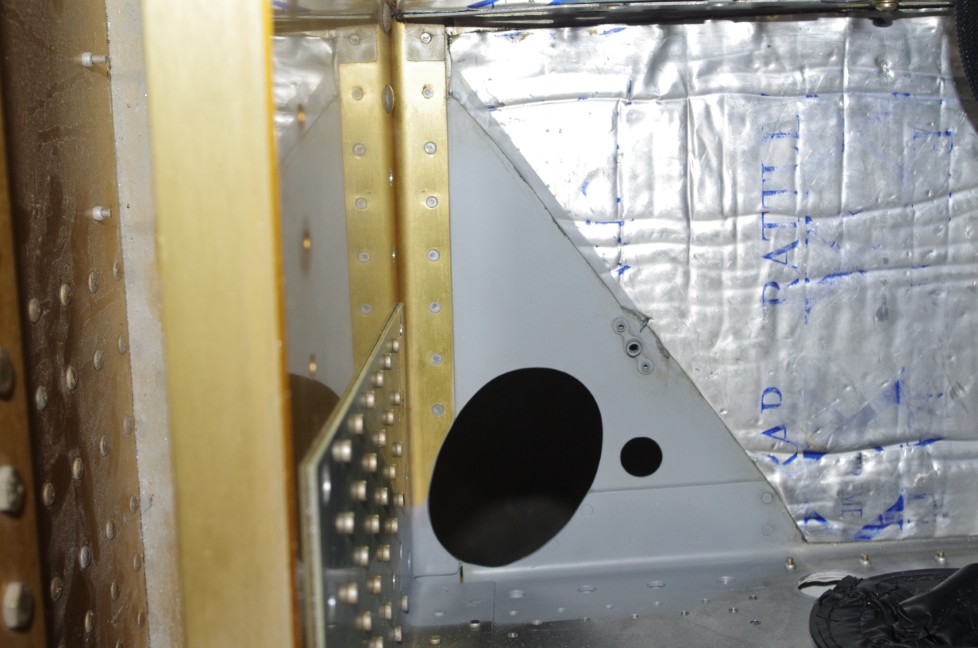
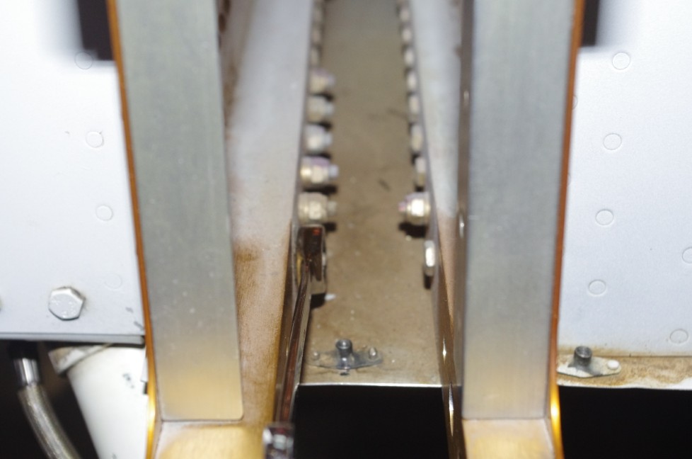
Remove F-1004F Center Section Upright Bar and F-1004N Stiffener Angles for easier hand access to spar interior and lock nuts for weldment mount bolts.

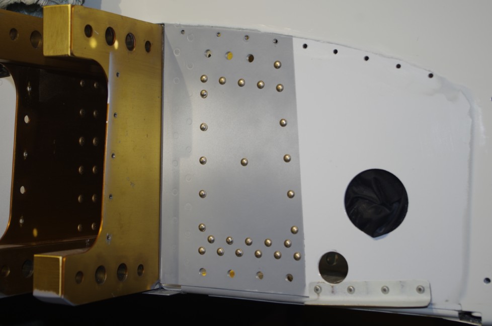
The custom drill guides made from 7/8″ steel bar made it easy to hold firmly with a box end wrench.  This compares to the round drill guides provided in the Vans kit. See Service Bulletin Steps 19 – 22.

SB00007 – REV 2 (4-Closure)

After the gear weldment installation, the plane was reassembled basically in reverse order. During this period, elements needed for the annual condition inspection were also performed.

Installation of gear legs, brake pad replacement, and wheel attachment.


This photo shows us using a long brass rod to drive wing bolt insertion when attaching the wings. This was probably the most difficult part of the closure process.


Views of the wing bolt installation…


My previous paint job had left some parts of the wing under the fairings without paint covering.  The opportunity was used to rectify this situation.

SB00007 – REV 2 (3-Install)

Drilling for the spar hole and test fitting the gear weldment followed the Bulletin instructions. A detailed description of my process can be found in a subsequent post.  Next came the side doubler installation.

Since the left and right doubler plates are mirror images, one plate on the outside was used to get an idea where the final holes would be located. Note the three double-flush rivets in the upper right of the photos.


Holes were then drilled in the fuselage sides. The gear weldment was test fit again with the side doublers in place.


Vans supplied templates and a drill guide (for perpendicular orientation) were used to drill the AN4 holes through the fuselage side, custom made shims and gear weldment. The shims were fabricated by hand to exactly fit the gap between the gear weldment and the side doubler plate. Shims were generally tapered in a range from .020″ to .070″ depending on the location.


This photo show all the holes match drilled on the right side skin.


The side doublers were prepped and primed before being riveted into place.


Weldment final fitting and bolt attachment followed.


More views of the final bolt attachments.


All bolts were torqued to spec, then highlighted as complete with orange torque seal.


The refurbished F-1004J Stiffener Angles and F-1004N Center Section Upright Bar were then reinstalled.


Finally the F-1099F Wing Root Fairing Supports were attached.

SB00007 – REV 2 (2-Remove)

Unbolting and removing the old gear mounts was relatively straightforward. A few specifics are described below.

My airplane has a #2 ground wire running along the left fuselage side from the rear batteries to the forest-of-grounds on the firewall.  This stiff cable made gear mount manipulation a bit more difficult than on the right side.


Drilling out three rivets and replacing with flush rivets on both sides was required for installation of the new F-01004T Center Section Side Plate Doublers.


Because the new gear weldment tube is a larger diameter than the original version, the bottom hole needed to be enlarged about 1/16″ – 1/8″.  I used a Dremel sanding drum to accomplish the larger hole. The interior and edges with exposed raw material was treated with self-etching primer.


Self-etching primer was utilized not only on the interior sections, but also on nicked or scratched parts (legs, weldments, spars…)


Inspection of the F-1004J Center Section Upright Bars and F-1004N Stiffener Angles revealed some corrosion on the untreated aluminum surfaces on the right side.  I assumed this came from the paint stripping process done earlier when the plane was repainted. Regardless of origin, these parts on both sides were removed, cleaned, treated with alodine and then primed.  A side benefit of removing these parts was I could fit my hand comfortably between the spar webs to access the nuts for the weldment bolts with a wrench.


SB00007- REV 2 (1-Setup)

My RV10 was built from parts received from Vans between 2013-2018, which means the WD-1021 Landing Gear Mounts were subject to Service Bulletin 00007 – Rev 2.  This document describes the issue of stress cracks propagating from the top attachment bolt and corner plate of the gear mounts. The initial annual condition inspection after the plane became airworthy was clear, but the second was more difficult to inspect due to dirt and grime in the area. Borescope inspection showed a 1″deformity of the powder coating on the right mount running parallel to the fuselage side – not emanating from the corner plate as indicated in the Service Bulletin. The deformity did not appear to indicate a crack in the mount. However, I made the decision at that point to replace the weldment as a precaution against potential further damage.  I ordered the repair kit from Vans, and it arrived quickly about a month later.

The initial Steps 1-16  in the instructions require many preparations to get the plane ready to address the gear mount itself – empty tanks, remove cowl, fairings, panels, seats, control sticks, brakes, wheels, and gear legs after elevating on a sawhorse capable of holding 1600 pounds.  This page shows elements of the preparation stages.


After removal of gear leg and wing root fairings, the plane was elevated onto the sawhorse using jacks under the tie down points in the wings.  A large ratchet strap was connected between the tail tie down and hangar wall to prevent the plane from rolling forward off the sawhorse.  Chocks were also positioned around the front wheel.


Removal of the cowl and wings then followed.  I had retained the wing cradles from the original build, so used them to store the wings during the project.


Gear legs removed in the left photo.  The right photo showed brake pads needed replacement, so this was added to the annual condition inspection TO-DO list.


A side view of the lower mount attachment bolts through the front spar can be seen. The F-1099F wing root fairing supports also needed to be removed.


SAWHORSE CONSTRUCTION

The sawhorse was constructed primarily of 2×6 lumber to the 32″ high and 48″ wide specification indicated in the Service Bulletin. Cross bracing and plywood webbing were included to provide dimensional stability and ensure the 1600 load capacity.


A slot for the padded top piece was designed into the upper cross member. Cross members were fastened to the base legs with 3/8″ bolts and deck screws.


The top was 12 x 48 x 3/4 plywood covered with 1.5″closed cell foam and a nylon stretch material. The 2×4 center slot fit into the upper cross member and was screwed into place with 3″ deck screws.


KSCR Takeoff

It was a beautiful Fall day to visit a nearby friend and talk about his RV10 build project. The weather was perfect for a calm flight home.

OK Arrival

Normally I do not fly in hard IMC conditions, but a long trip from North Carolina to Oklahoma can sometimes bring unexpected weather into the flight path. The landing shown here was at KRNO, El Reno, OK after about six hours of flight time from the East Coast.

Sport Aviation Article

Recognition of homebuilt effort for my plane appeared in the October edition of EAA’s Sport Aviation magazine.  The article speaks for itself.

N190XB 3D Panel v02

Another updated panel file.

August 2024 – X09 Arrival

My first solo cross-country flight was from North Carolina to Texas to visit family.  This flight of firsts also saw my first low pass approach and first grass field landing.  All went well and the plane flew beautifully.  Many thanks to Rich and Nancy for their hospitality.

Post Navigation