My RV10 was built from parts received from Vans between 2013-2018, which means the WD-1021 Landing Gear Mounts were subject to Service Bulletin 00007 – Rev 2. This document describes the issue of stress cracks propagating from the top attachment bolt and corner plate of the gear mounts. The initial annual condition inspection after the plane became airworthy was clear, but the second was more difficult to inspect due to dirt and grime in the area. Borescope inspection showed a 1″deformity of the powder coating on the right mount running parallel to the fuselage side – not emanating from the corner plate as indicated in the Service Bulletin. The deformity did not appear to indicate a crack in the mount. However, I made the decision at that point to replace the weldment as a precaution against potential further damage. I ordered the repair kit from Vans, and it arrived quickly about a month later.
The initial Steps 1-16 in the instructions require many preparations to get the plane ready to address the gear mount itself – empty tanks, remove cowl, fairings, panels, seats, control sticks, brakes, wheels, and gear legs after elevating on a sawhorse capable of holding 1600 pounds. This page shows elements of the preparation stages.
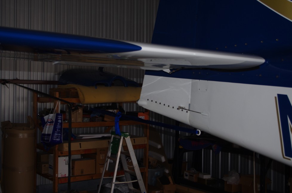
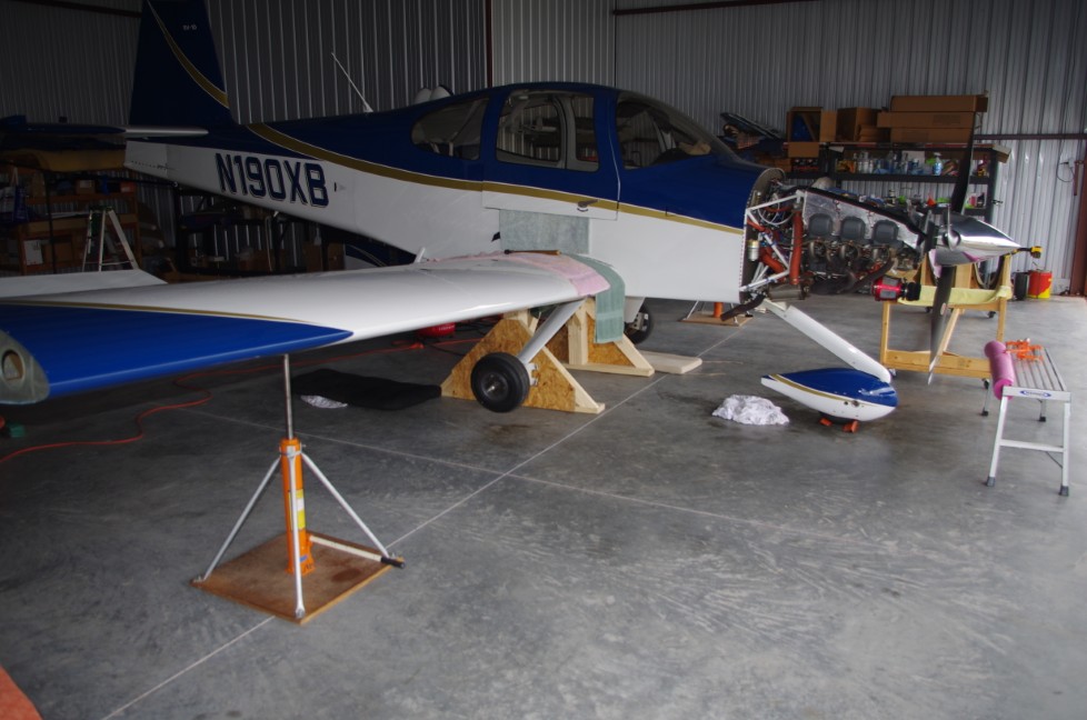 After removal of gear leg and wing root fairings, the plane was elevated onto the sawhorse using jacks under the tie down points in the wings. A large ratchet strap was connected between the tail tie down and hangar wall to prevent the plane from rolling forward off the sawhorse. Chocks were also positioned around the front wheel.
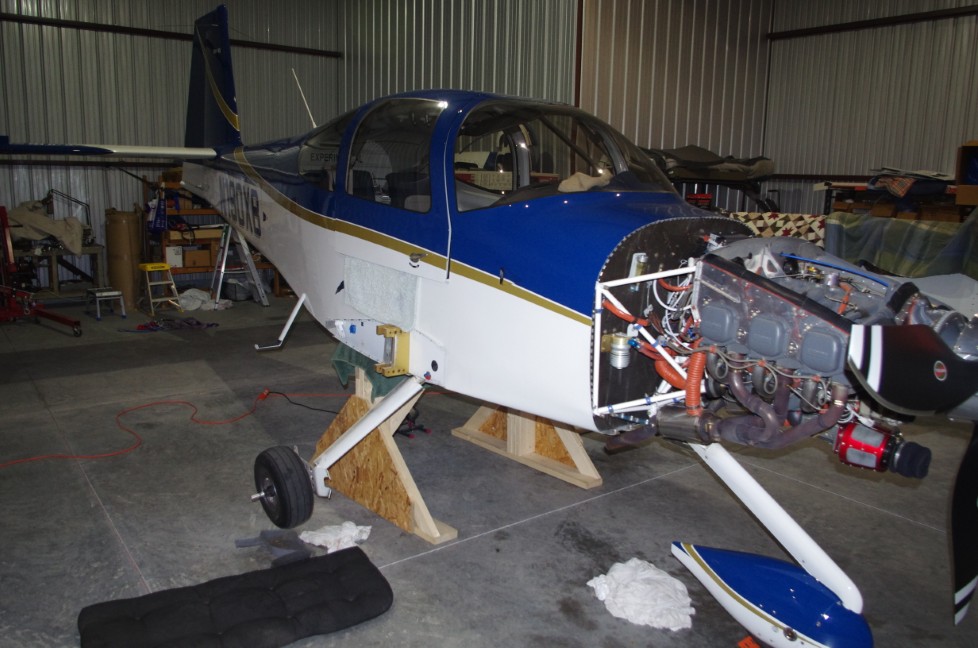
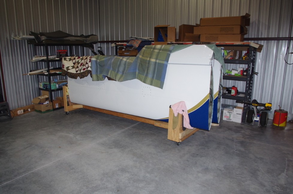 Removal of the cowl and wings then followed. I had retained the wing cradles from the original build, so used them to store the wings during the project.
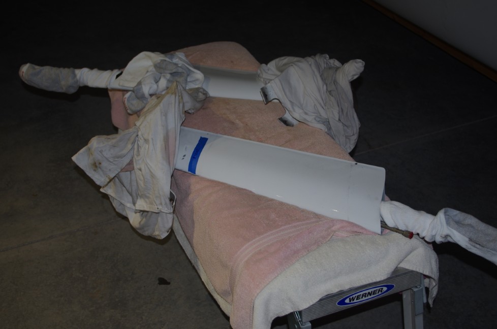
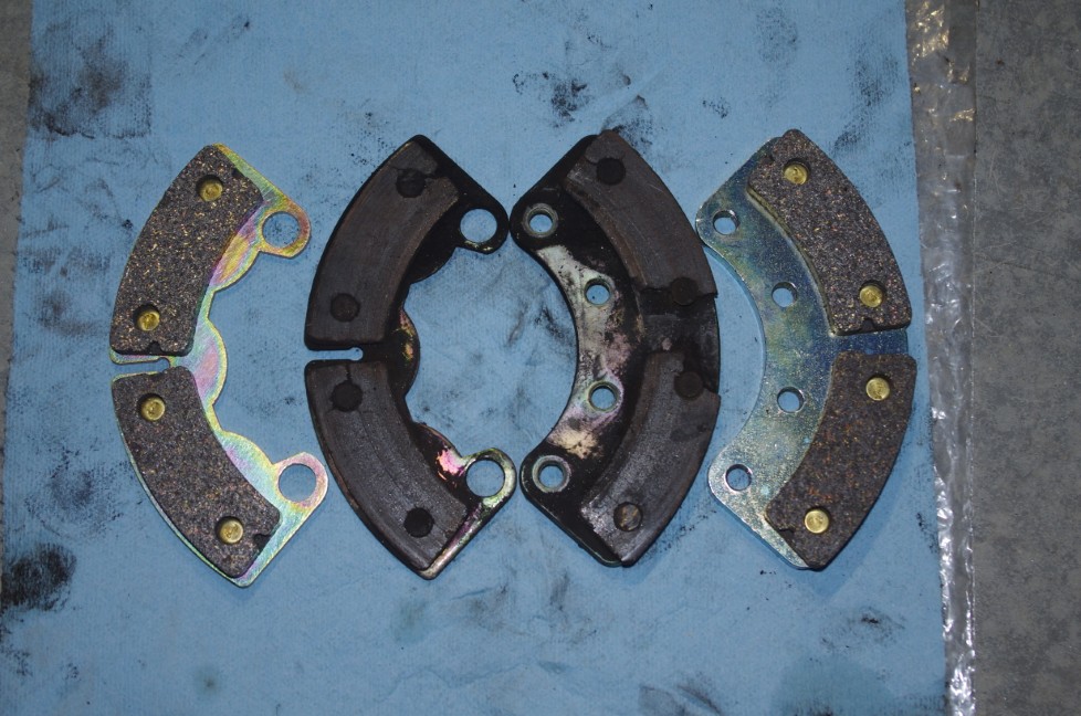 Gear legs removed in the left photo. The right photo showed brake pads needed replacement, so this was added to the annual condition inspection TO-DO list.
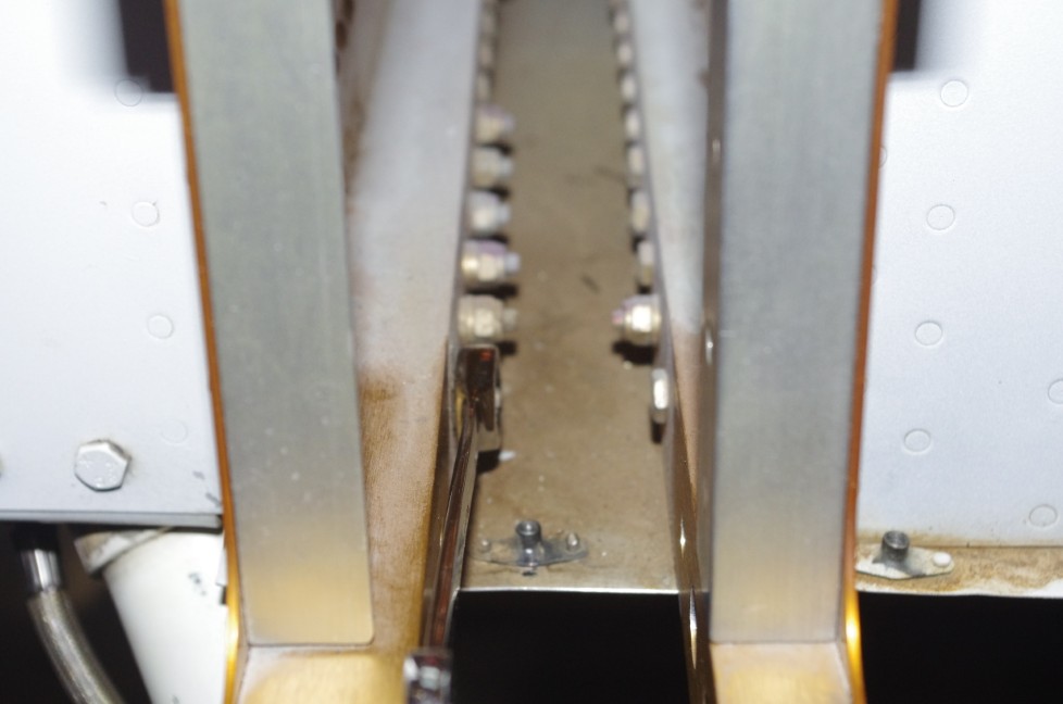
 A side view of the lower mount attachment bolts through the front spar can be seen. The F-1099F wing root fairing supports also needed to be removed.
SAWHORSE CONSTRUCTION
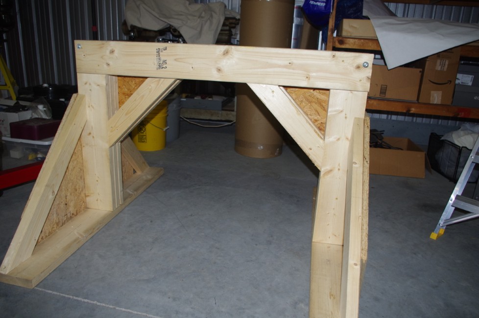
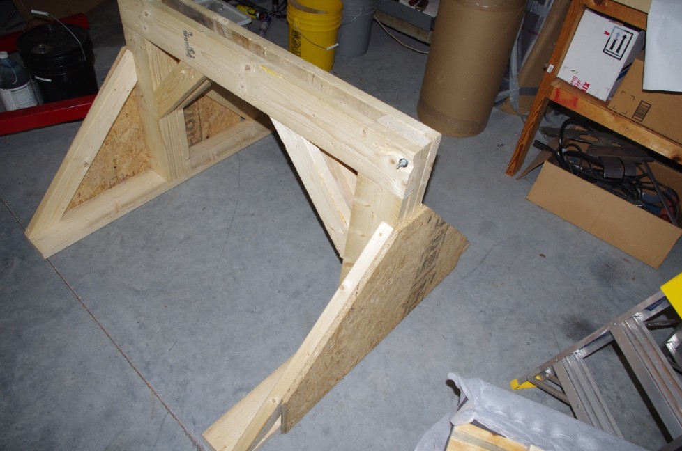 The sawhorse was constructed primarily of 2×6 lumber to the 32″ high and 48″ wide specification indicated in the Service Bulletin. Cross bracing and plywood webbing were included to provide dimensional stability and ensure the 1600 load capacity.
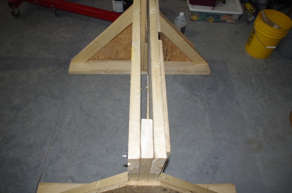 A slot for the padded top piece was designed into the upper cross member. Cross members were fastened to the base legs with 3/8″ bolts and deck screws.
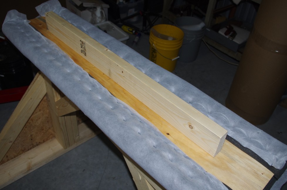
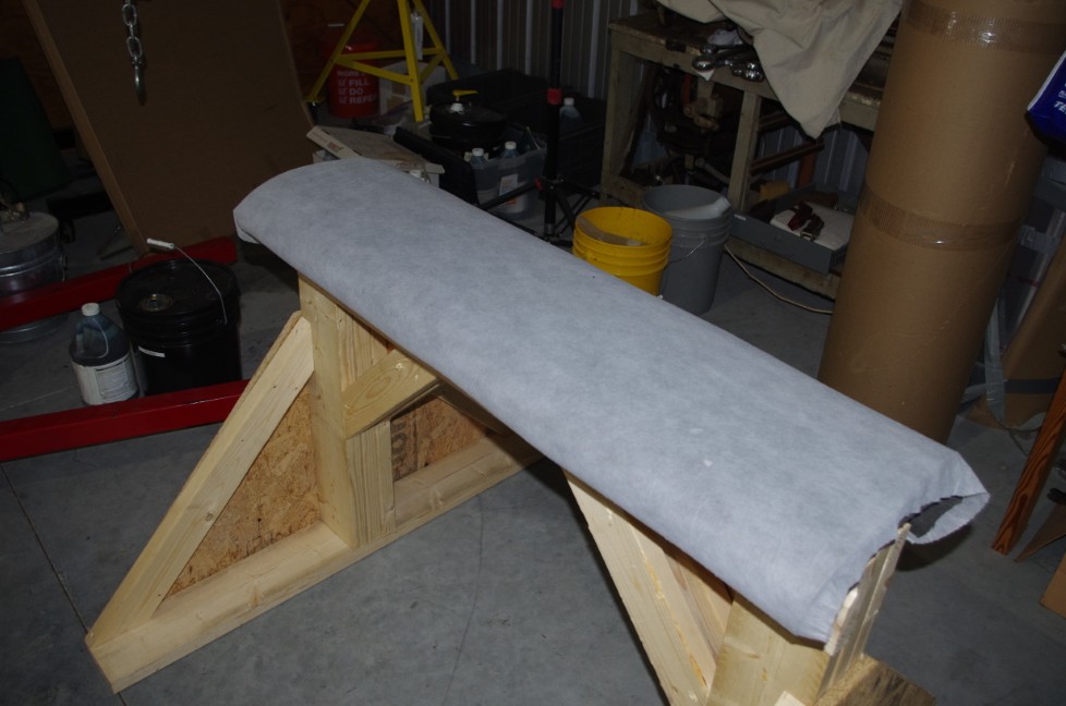 The top was 12 x 48 x 3/4 plywood covered with 1.5″closed cell foam and a nylon stretch material. The 2×4 center slot fit into the upper cross member and was screwed into place with 3″ deck screws.