Category Archives: Instrument Panel

Interior (2)

Further development of the interior included shaping the headliner backing and configuring the center console/armrest.

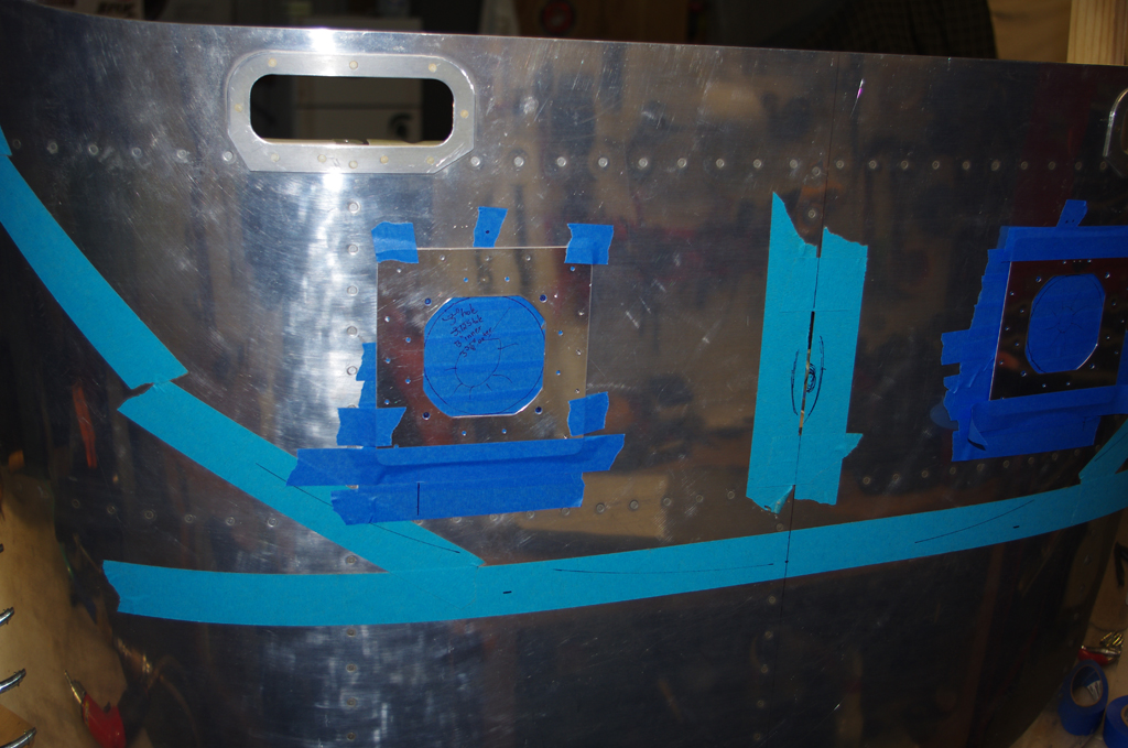
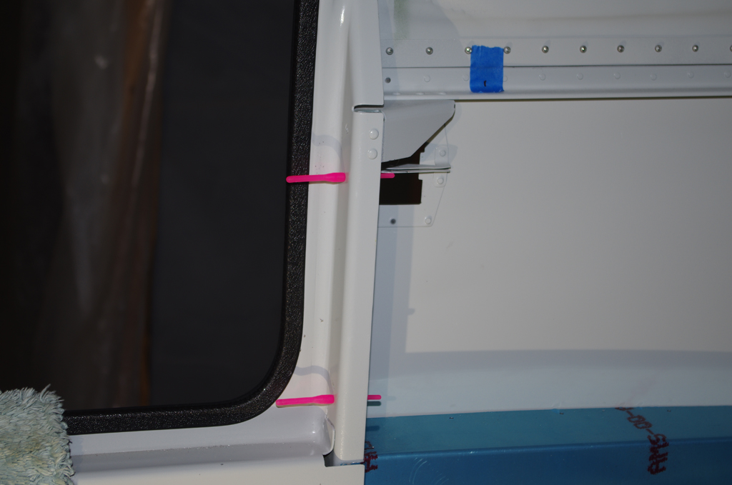
A tracing of the side window outline was laid against the fiberglass headliner template from Areosport Products. The fiberglass was rough shaped to the window contours, then finalized when test fitted into the canopy.  Further actions include additional shape refinements and covering the fiberglass backer with grey headliner material.  The lower side panels may also need relief to accommodate the thickness of the headliner at the longeron edge.


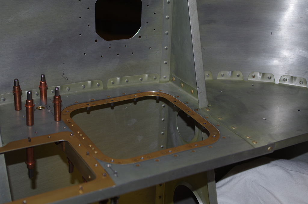
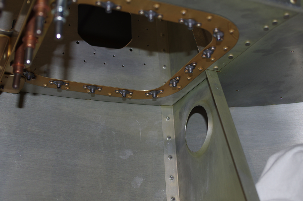
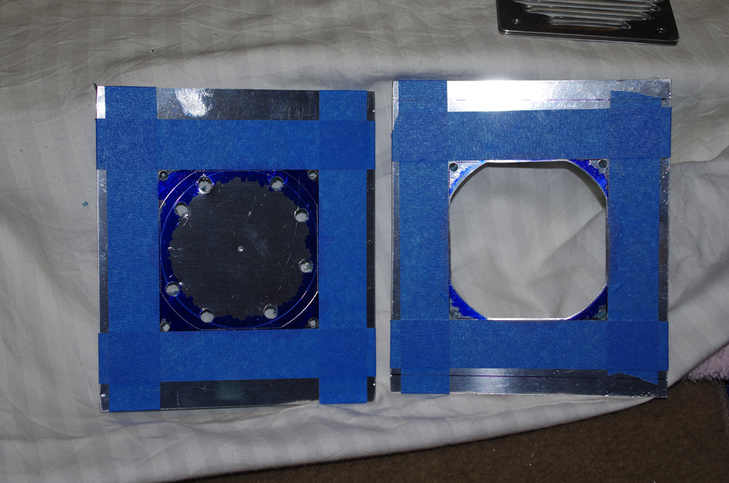
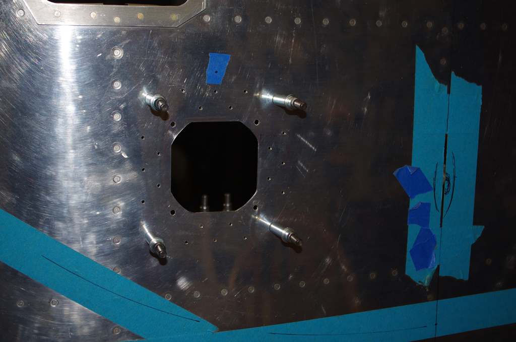
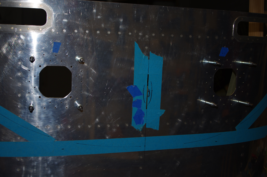
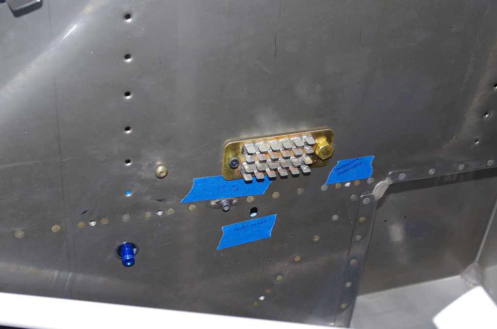
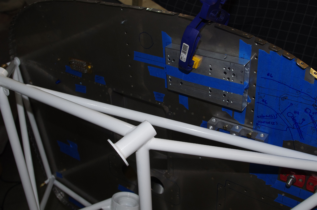
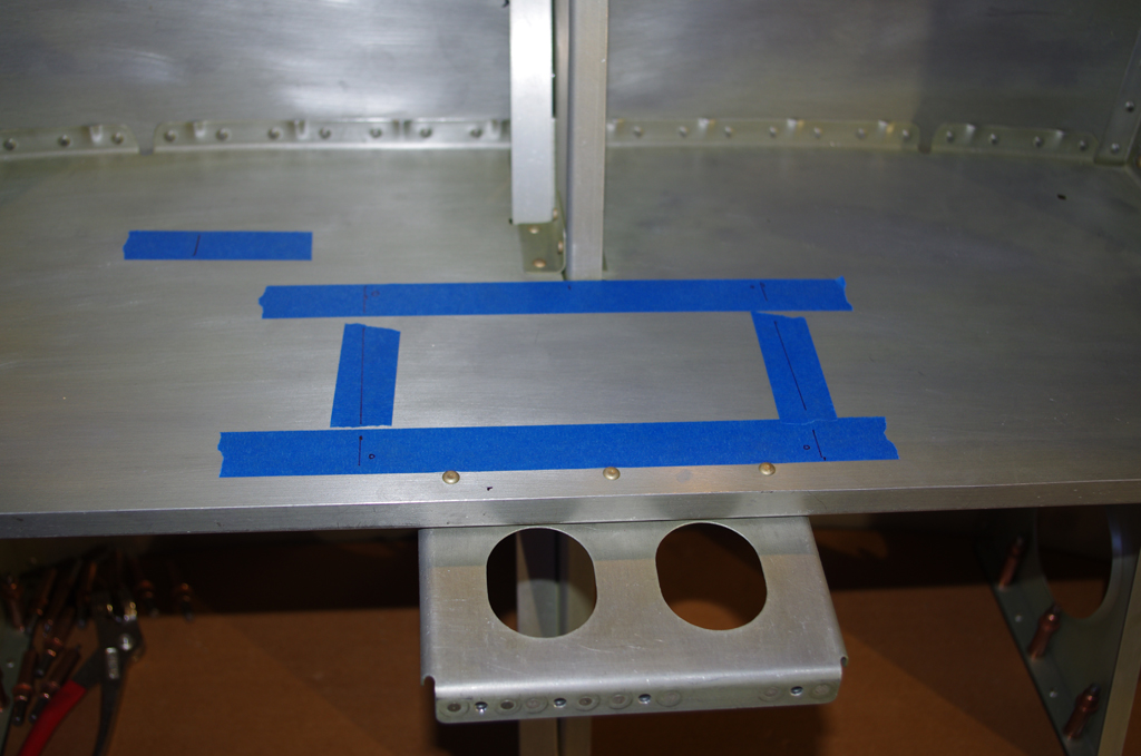
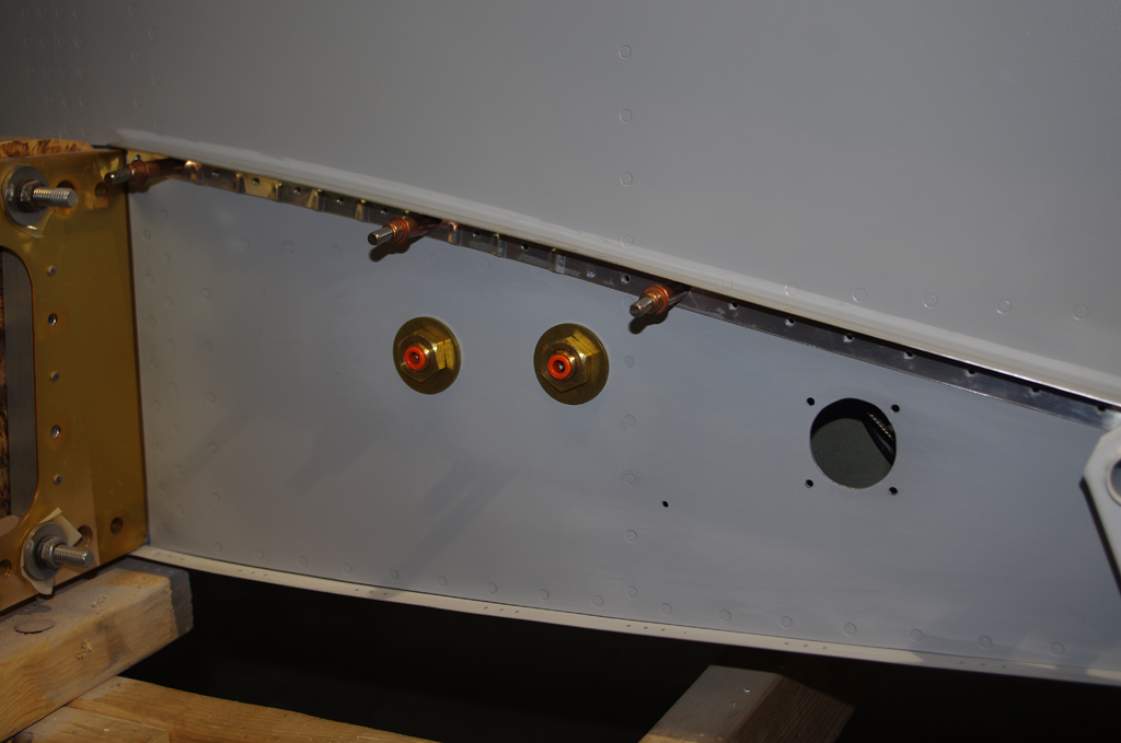
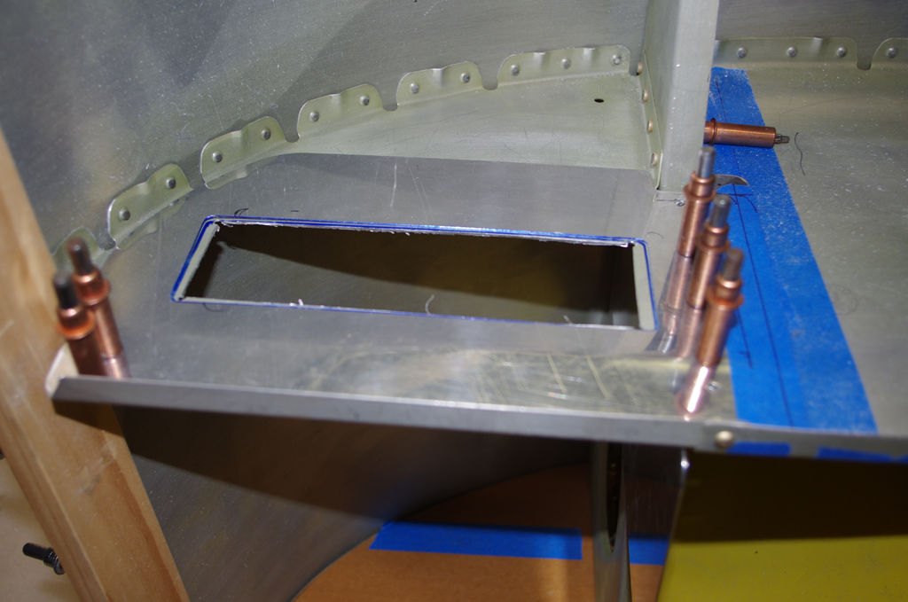
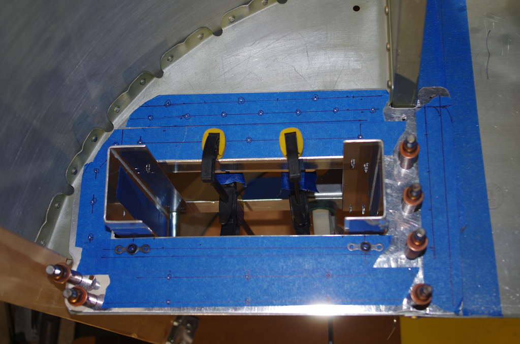
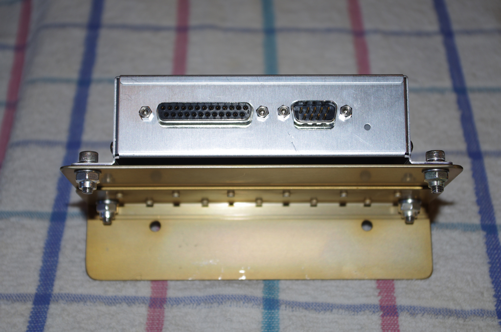
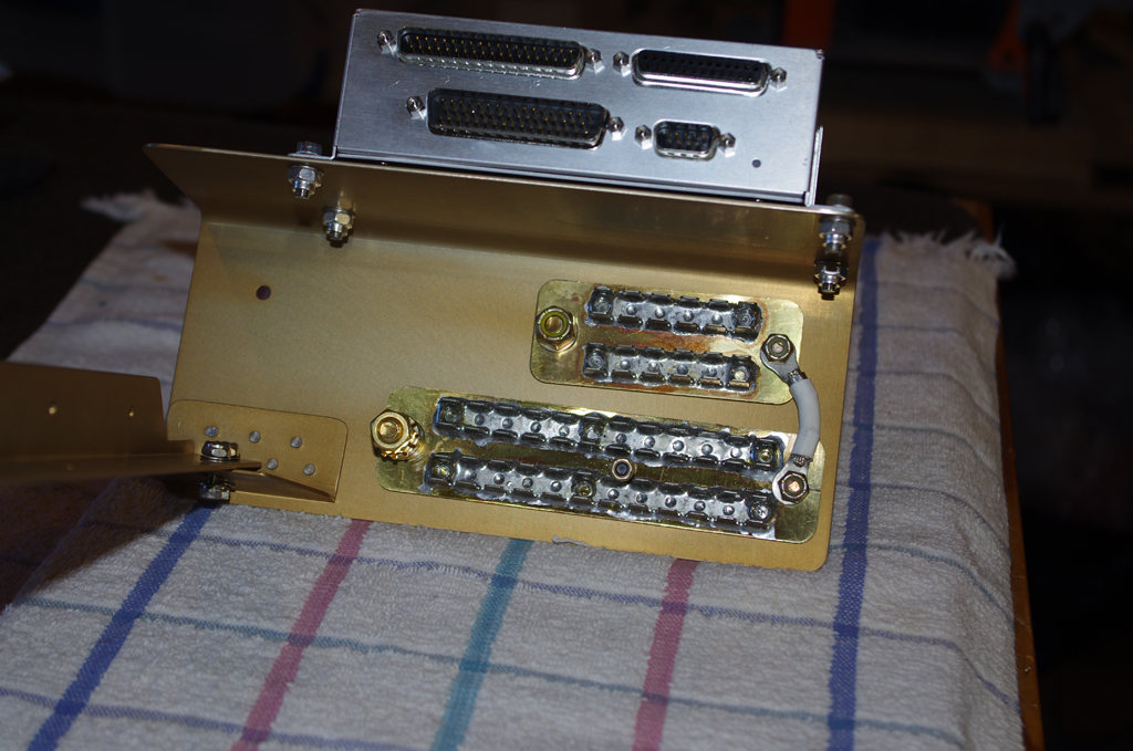
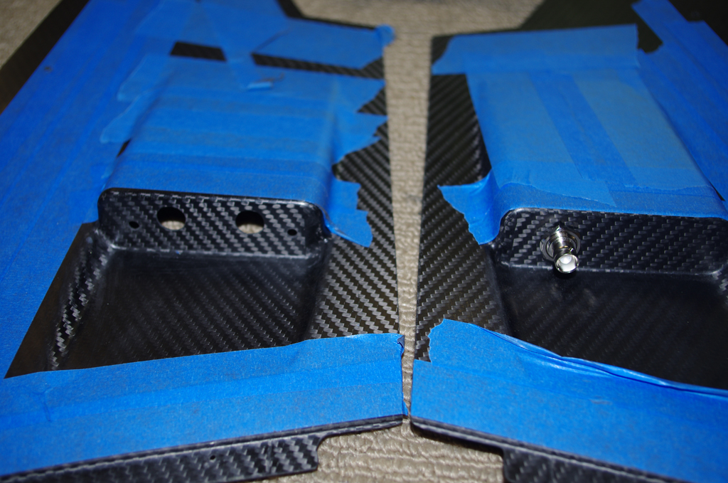
On the left are #8 ClickBond nutplates being glued into place.  Regular riveted nutplates could have been used here, but I wanted to avoid additional hole penetrations on structural elements whenever possible. On the right are holes cut into the forward center tunnel covers for heater cables and the AUX COMM connection.


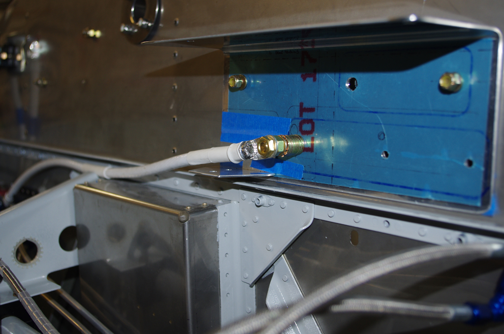
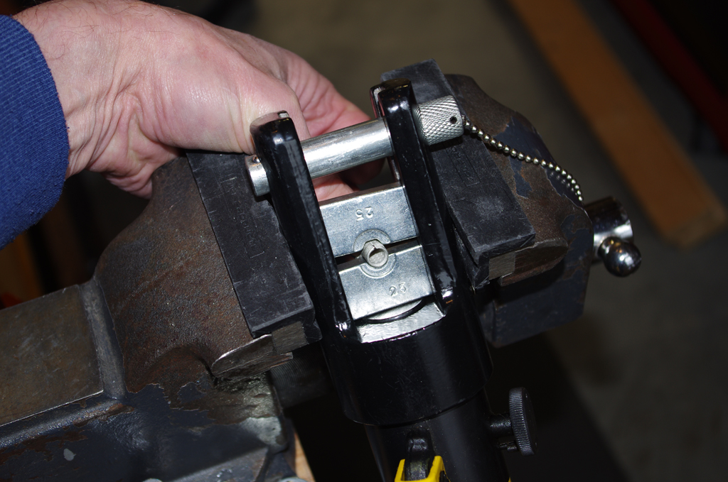
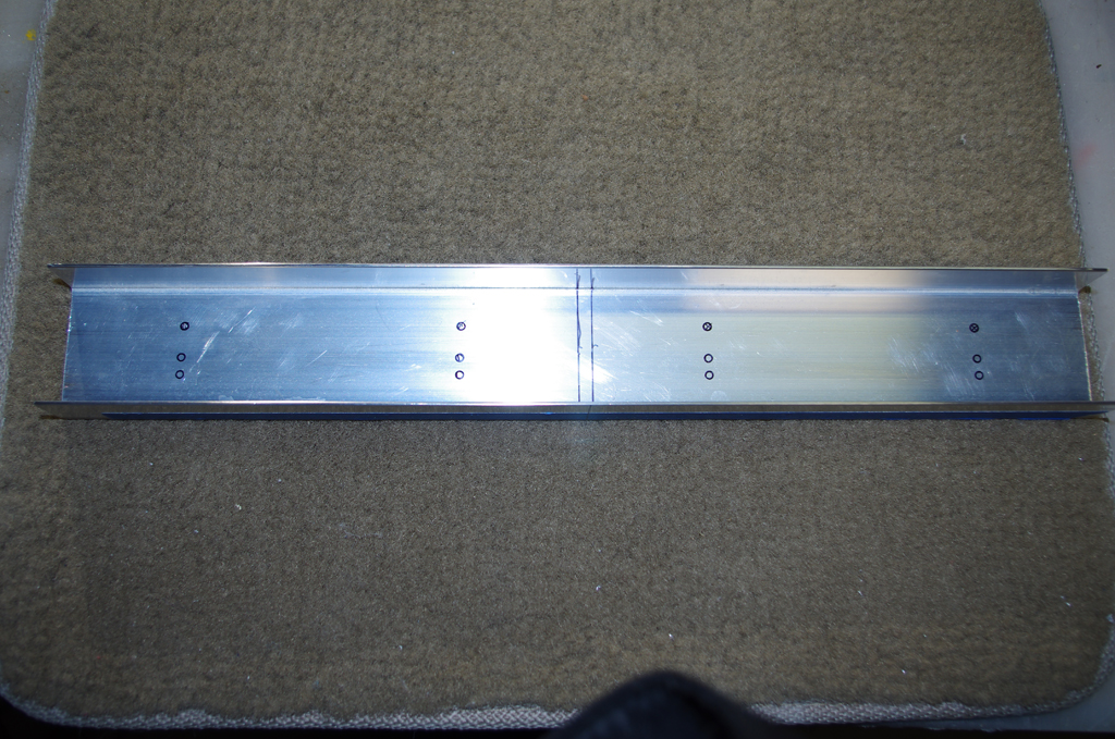
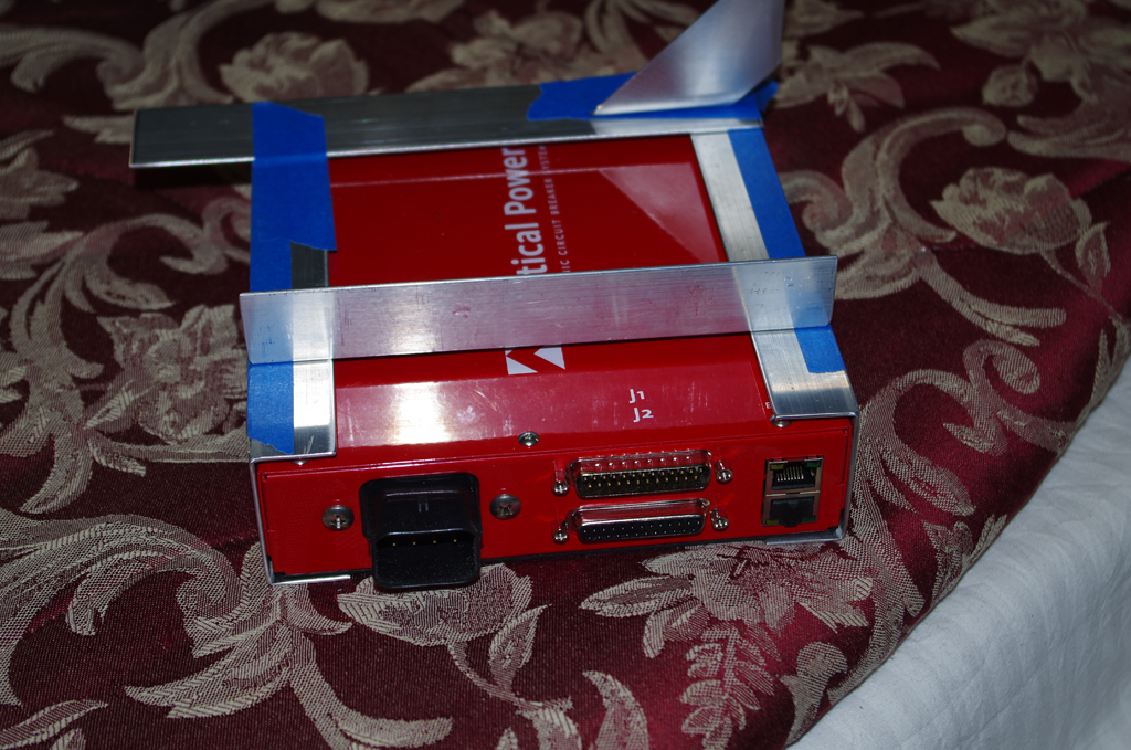
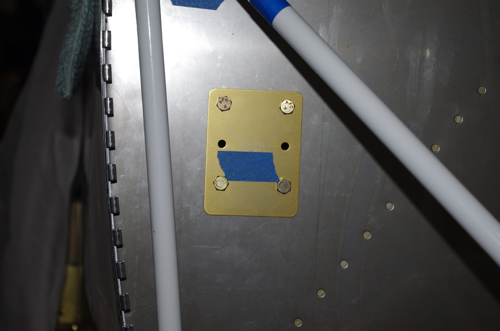
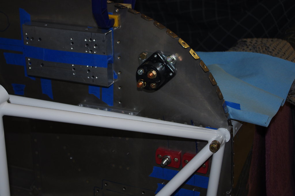
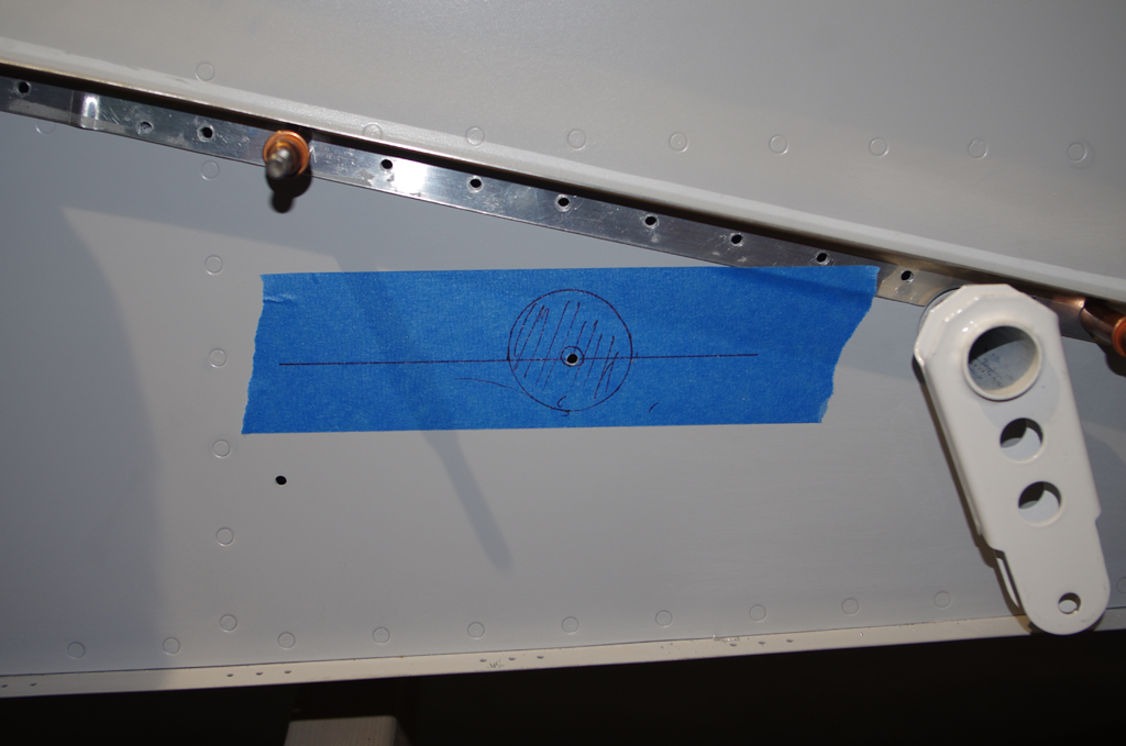
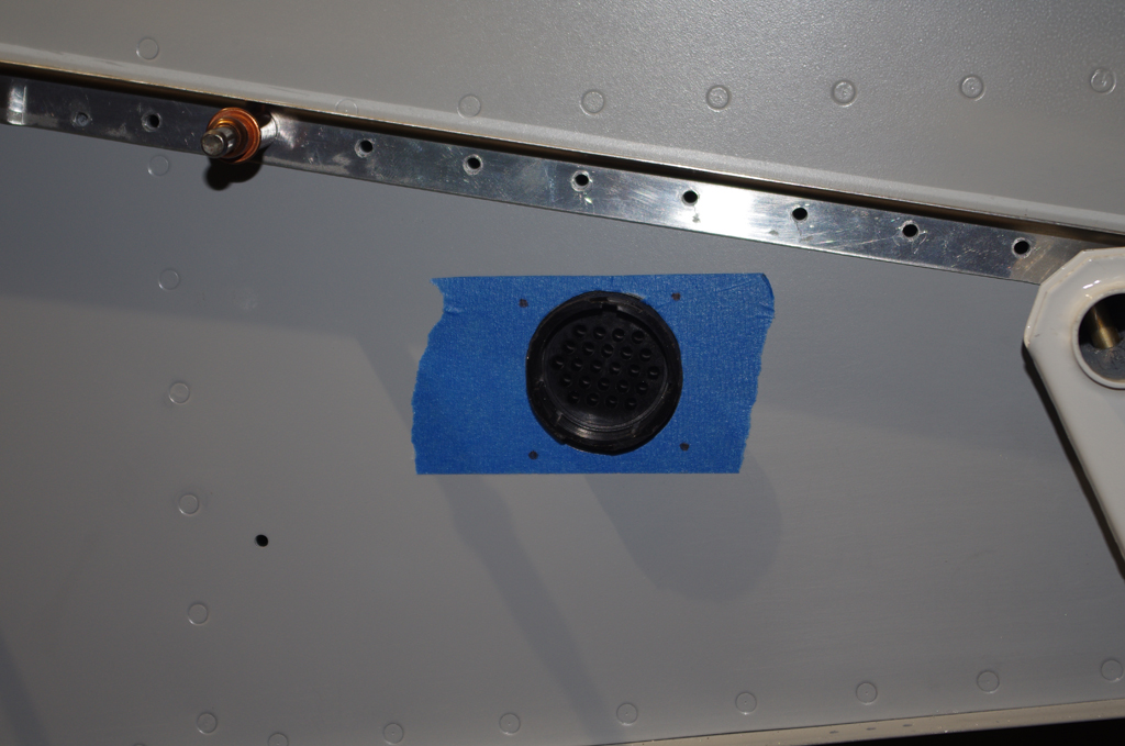
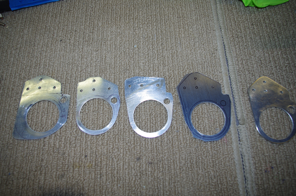
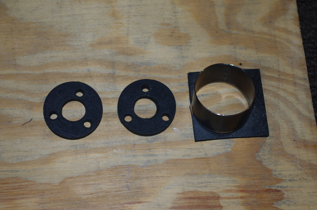
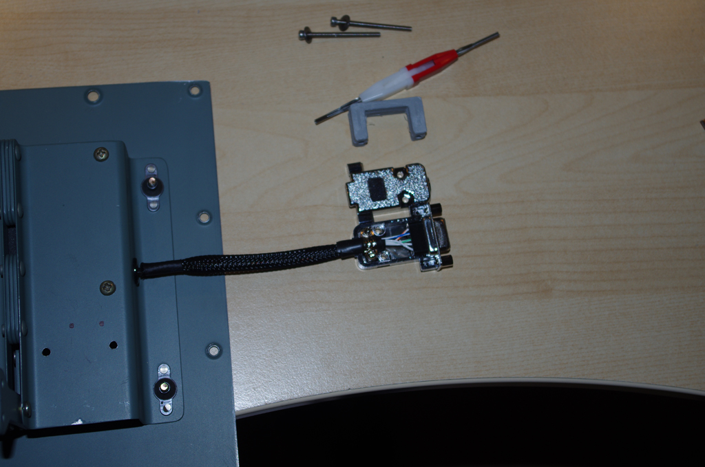
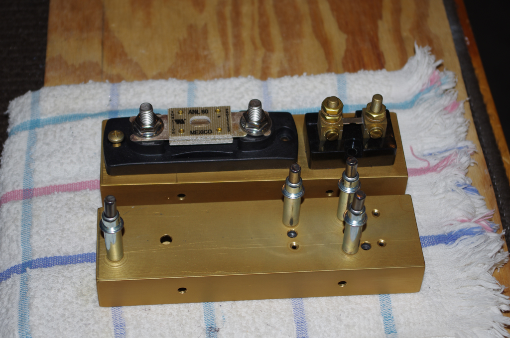
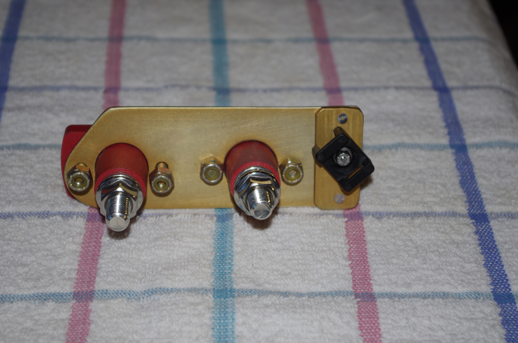
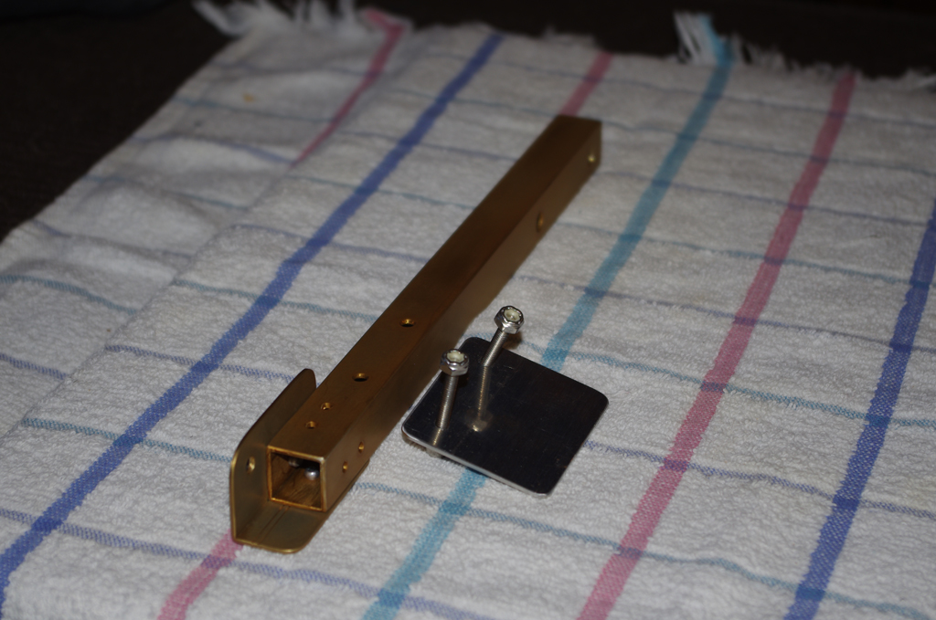
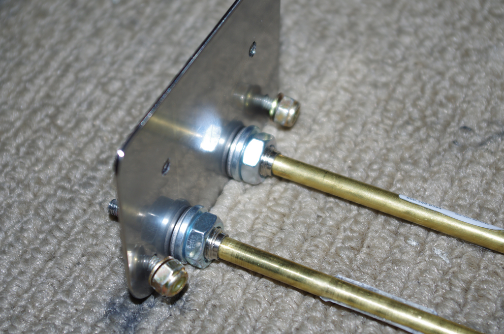
A .060″ stainless backing plate was made for the heater push-pull cables.  They require a D-shaped hole to keep the cable from rotating. Since I was not confident the carbon fiber side panels could withstand the stress without cracking, the approach to spread the forces across a larger area was taken.


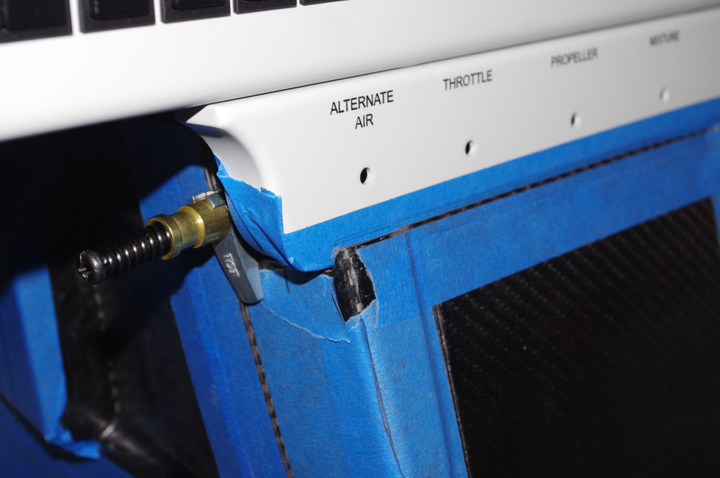
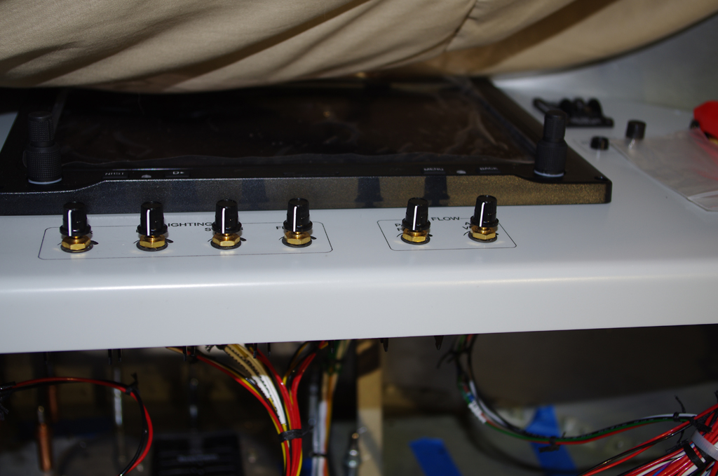
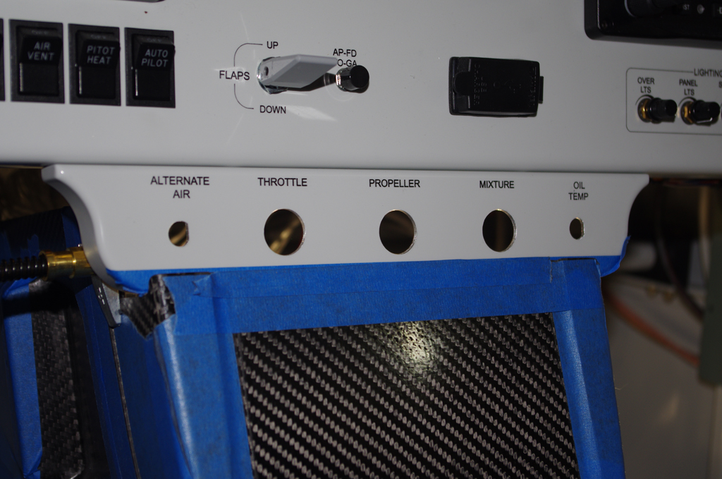
Here the Aerosport center console cover was rough fitted to the SteinAir control quadrant plate to the top and to the armrest base on the bottom.  Particular attention was paid to where the fuel selector valve would be located. Notice the small lower seam between the center cover and the armrest base.  This was achieved with a very slight tilt of the cover against the quadrant plate.


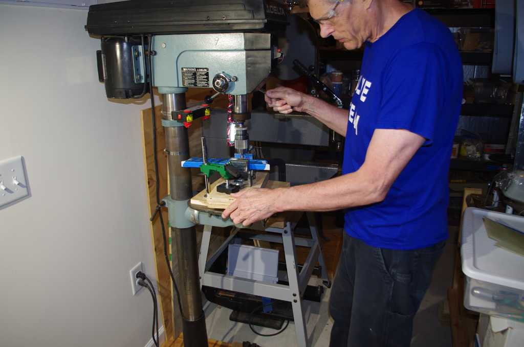
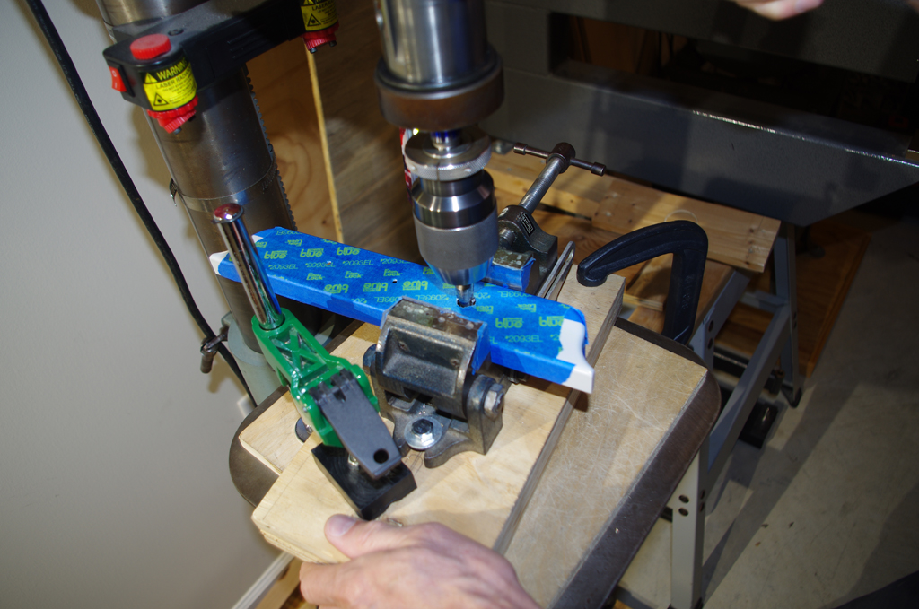
Once the test fit of the quadrant plate was complete, the 3/4″ holes for the control cables were made with a Unibit in the drill press.


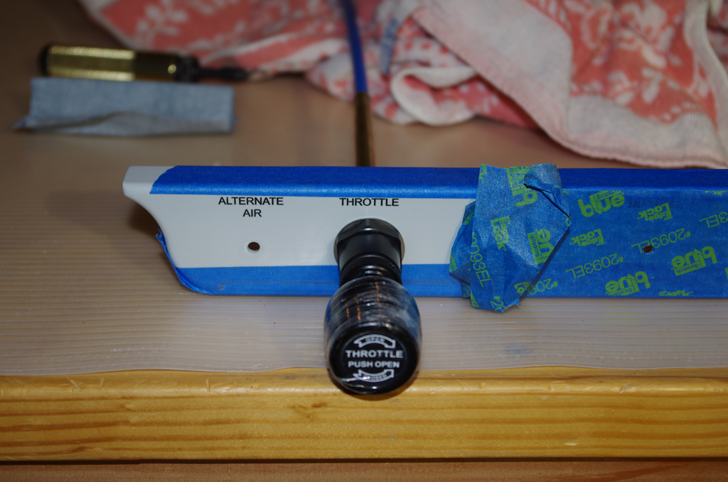
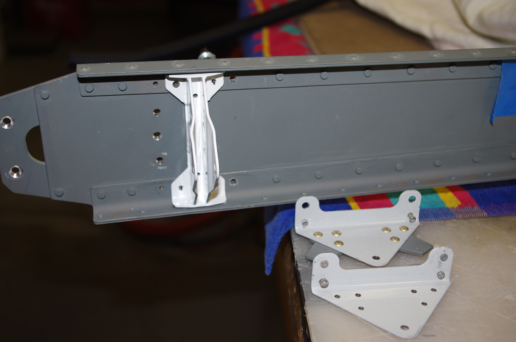
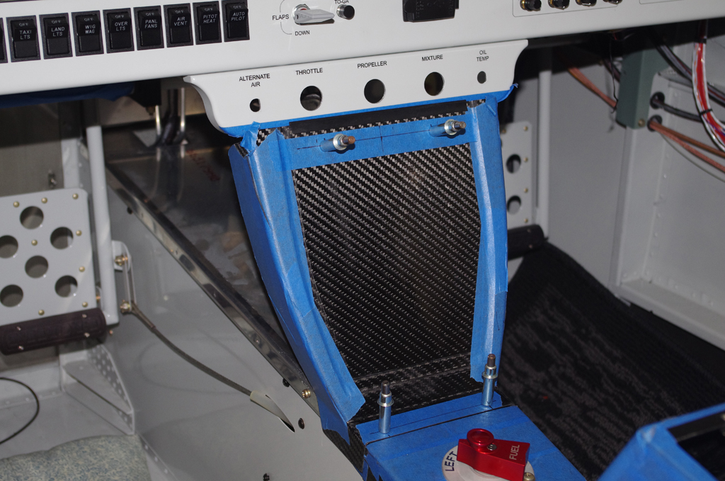
The throttle cable was checked in the quadrant plate before completing the remaining holes.  The photo at right shows the mounting plate for the center console provisionally attached to the now permanently installed quadrant plate.


The mounting plate viewed from the front and with the center cover in place.


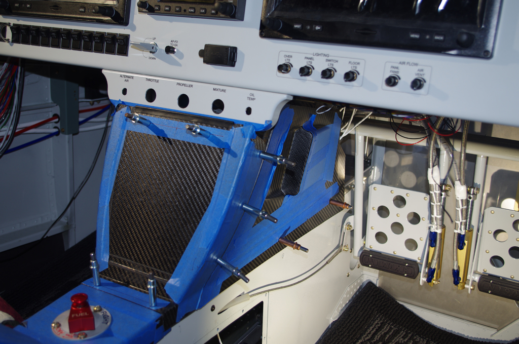
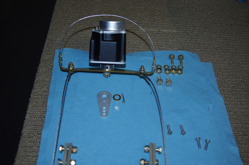
Next was drilling and fitting the Andair fuel valve selector in the lower armrest base. This was done very carefully and required about 6 hours to complete. The #10 screws shown in these photos are too high, interfering with the rotation of the selector.  They must later be replaced with others with a lower head to allow freedom of movement.


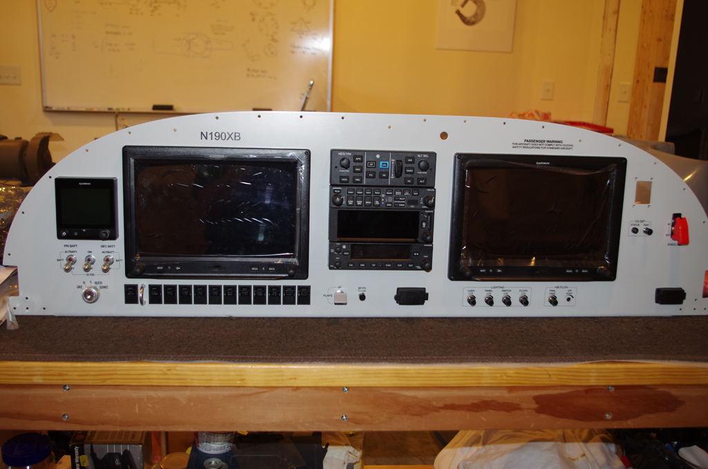
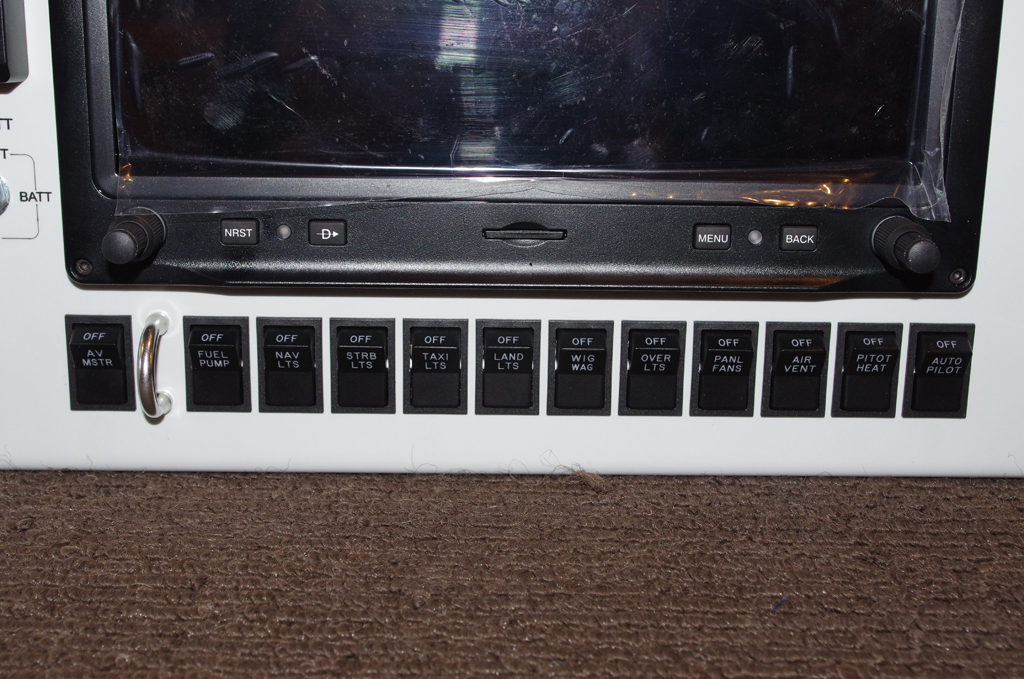
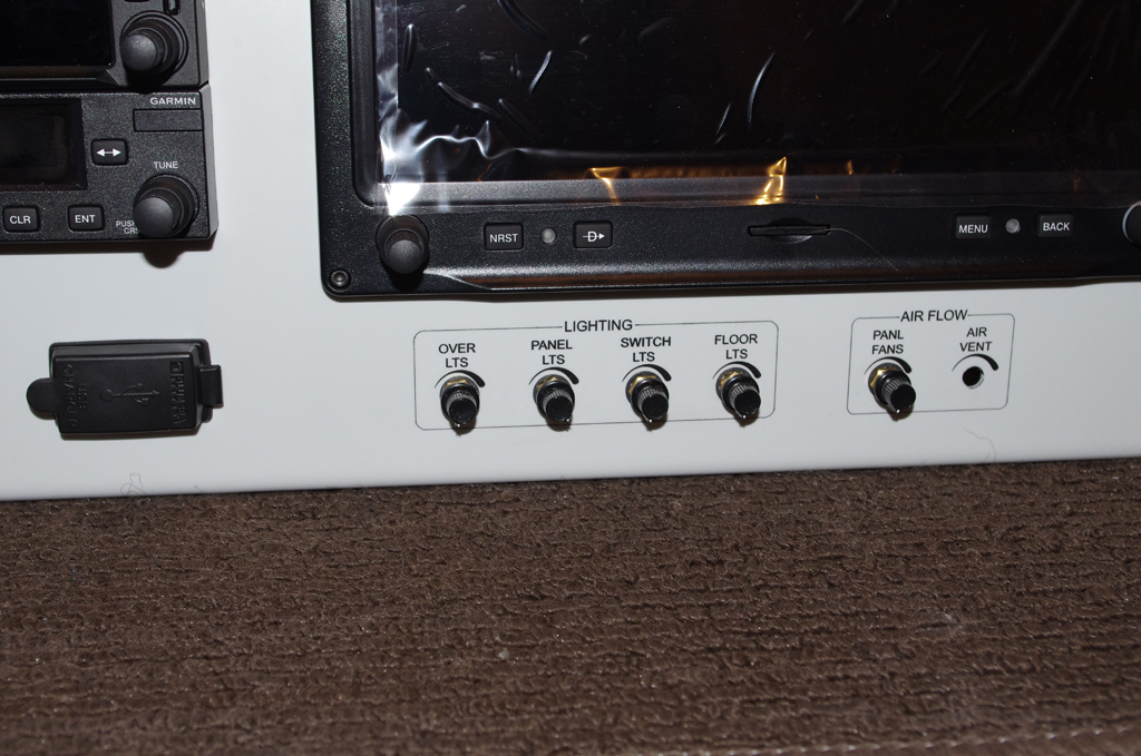
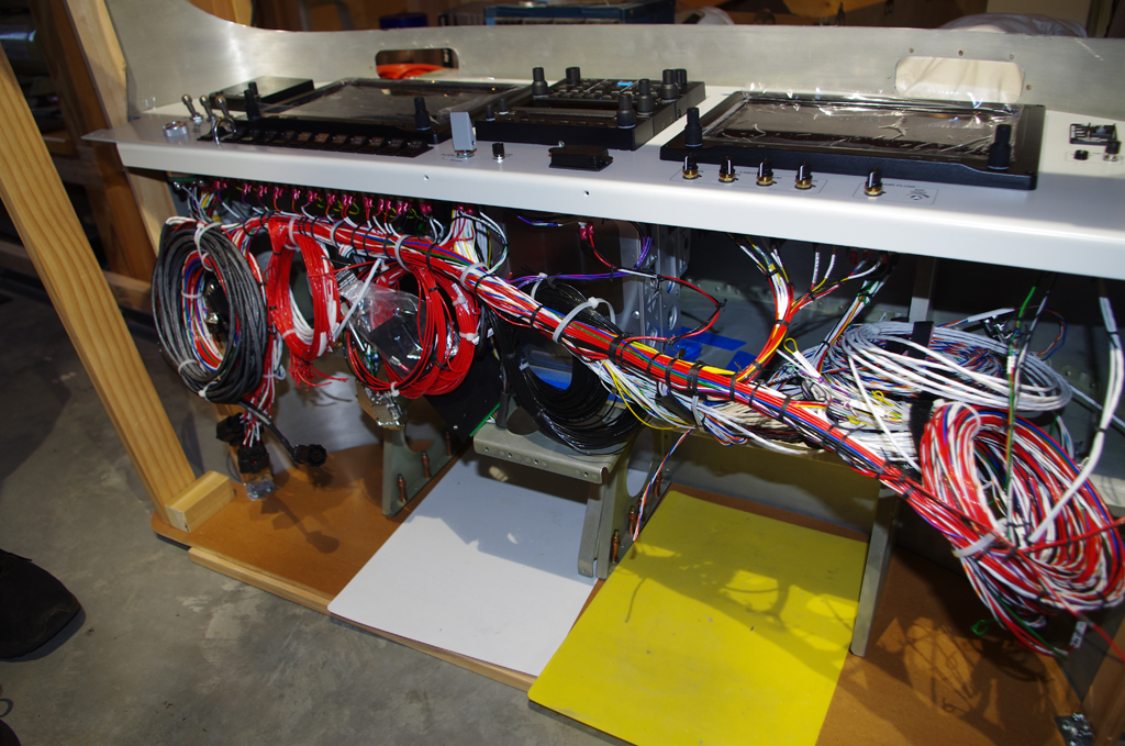
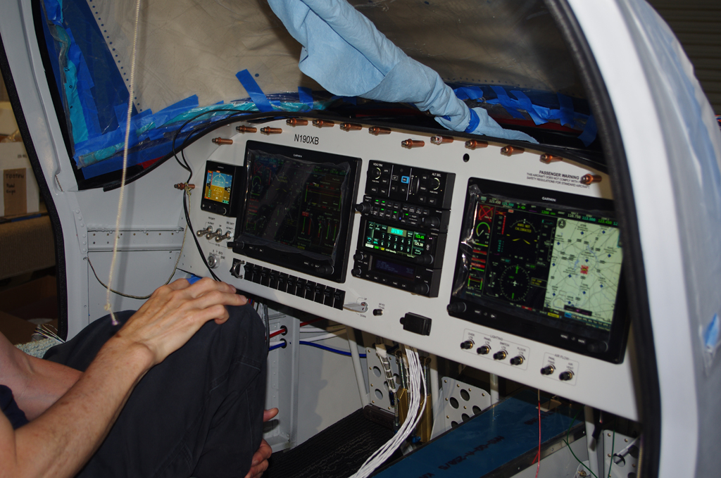
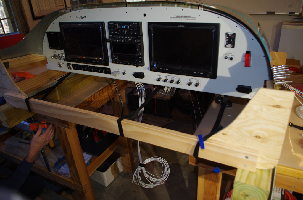
Here are interim view of the armrest, center console, side covers, and lower instrument panel. Up next are fitting the control cables, layout and installation of headphone/microphone jacks in the center console, armrest adjustments and other final configurations above the tunnel.


Instrument Panel (6)

Electrical testing with the G3X system continued after installation of the Series 2, 24-pin CPC wing root connectors and other interior devices.

The position of the wing root connectors needed to have enough clearance to be under the wing root fairing, but high enough for easy accessibility in the side panel cavity. Careful measurements were taken before the side penetration was done.


Additional holes in the left side were needed for the pitot and angle-of-attack (AOA) pneumatic tubes.  The left photo shows a trial installation of the brass, right angle push-to-connect bulkhead fittings.  The right photo shows the initially pulled configuration of the side wire bundles.  In retrospect, I would probably rearrange how some of these wires are run.


A custom nut plate backer was fabricated for each CPC connector.  This accessory will help fasten the connectors in the fuselage mid-shin.  The right photo shows a right angle strain relief shell and the nut plate backer with the wing root wire bundled pulled through them ready for CPC male pin termination.


The final CPC configuration – inside the mid-skin cavity and from outside the fuselage.  The outcome was very good (more on the testing later).


Custom ground block terminators were described in an earlier post.  One of them was installed in the rear seat area for access from the wing roots and the aircraft rear conduits, which feed wires from the rear section under the baggage/seat floors to the forward compartment. The right photo shows a series of prototype brackets for the forward air vents.


The Park Brake push-pull cable will be located in the left side air vent bracket.  Here a mock-up of the intended configuration is shown. While the vent is close to the brake lever, it does have a free range of motion and should have air flow impacted very much.  The final painted and installed bracket is on the right.


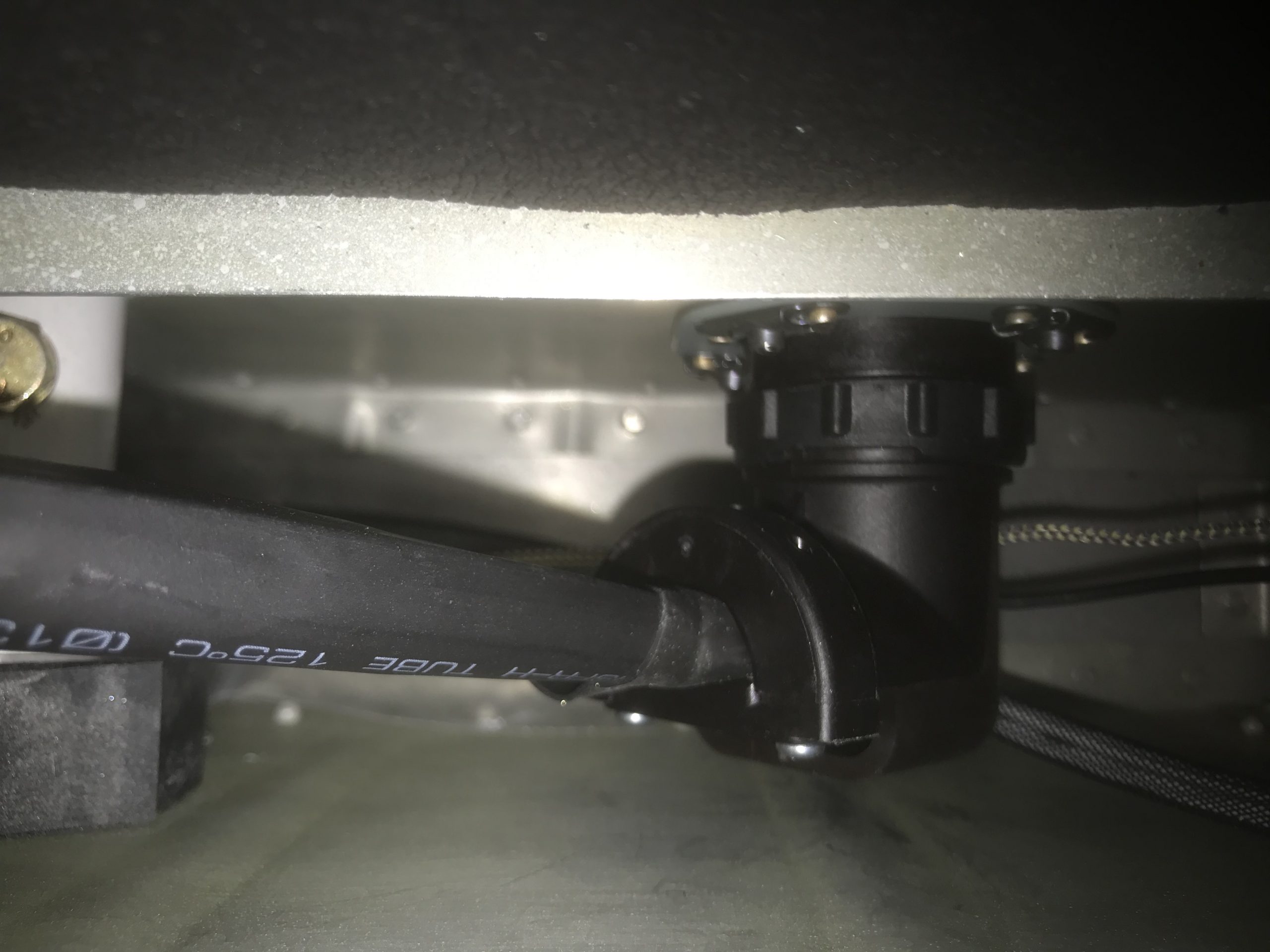
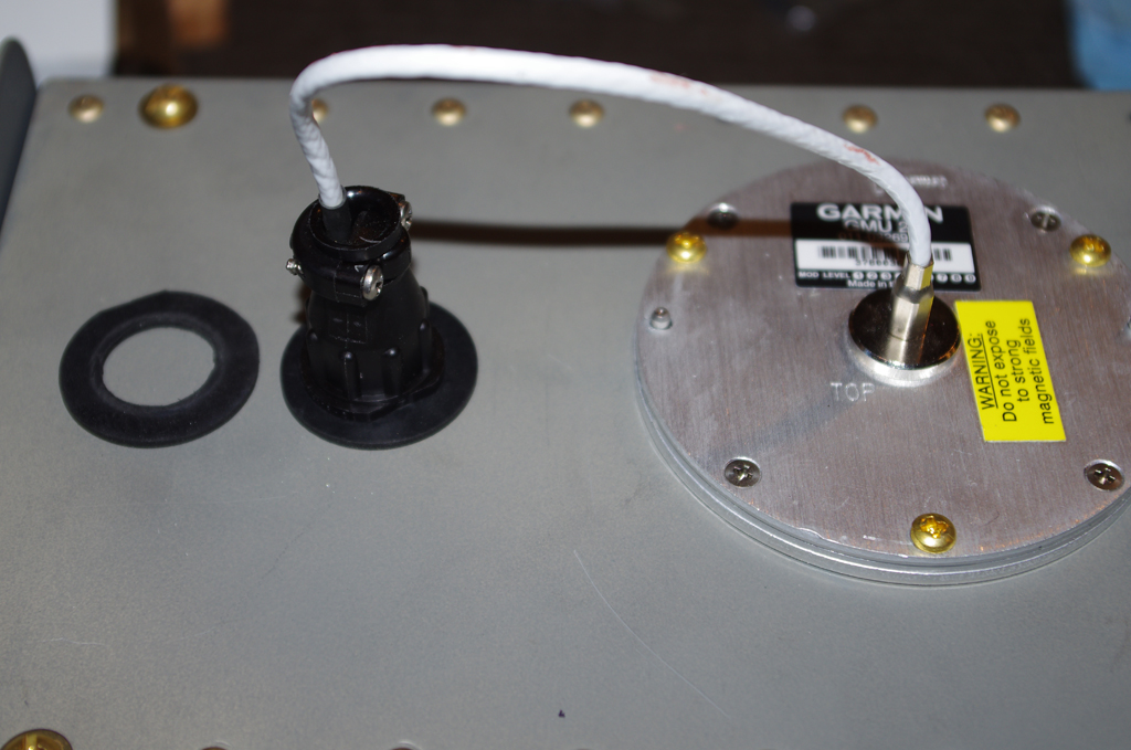
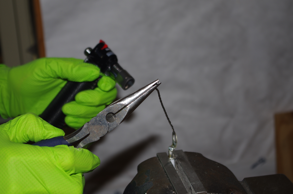
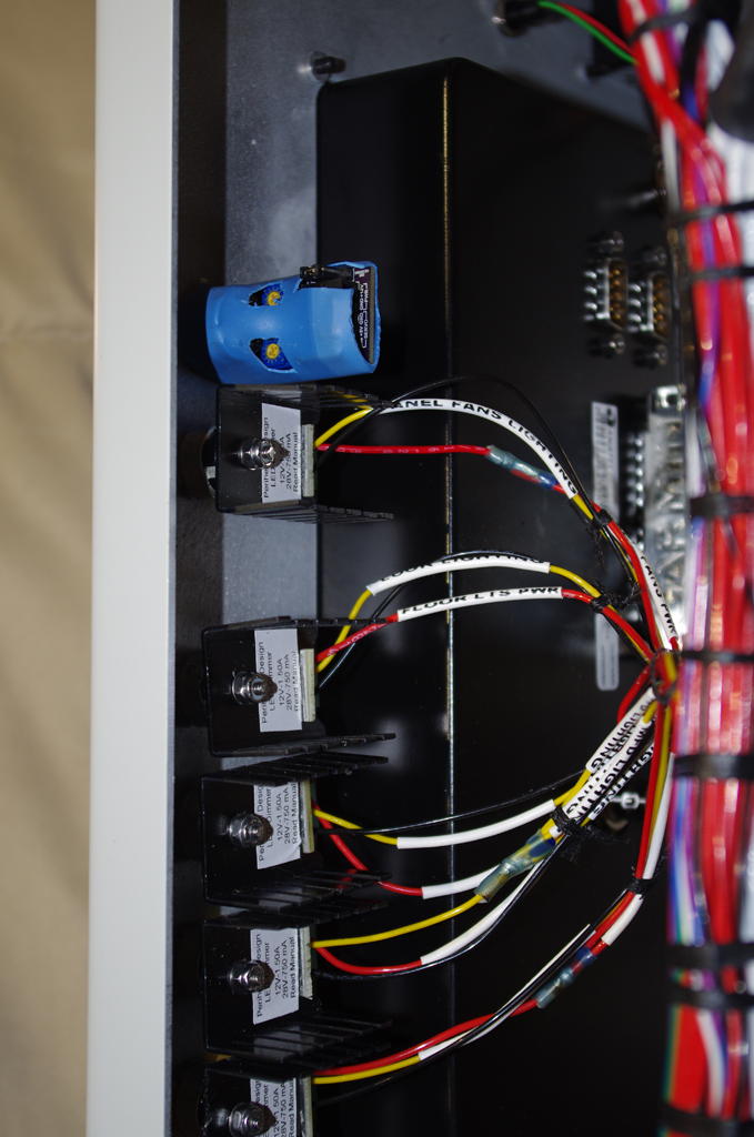
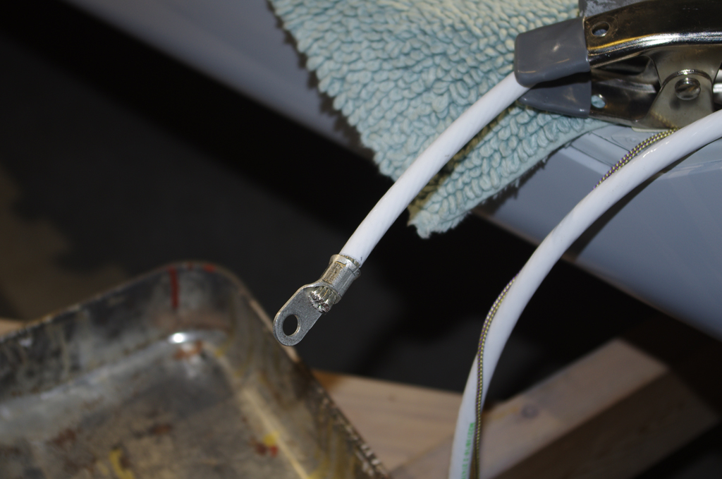
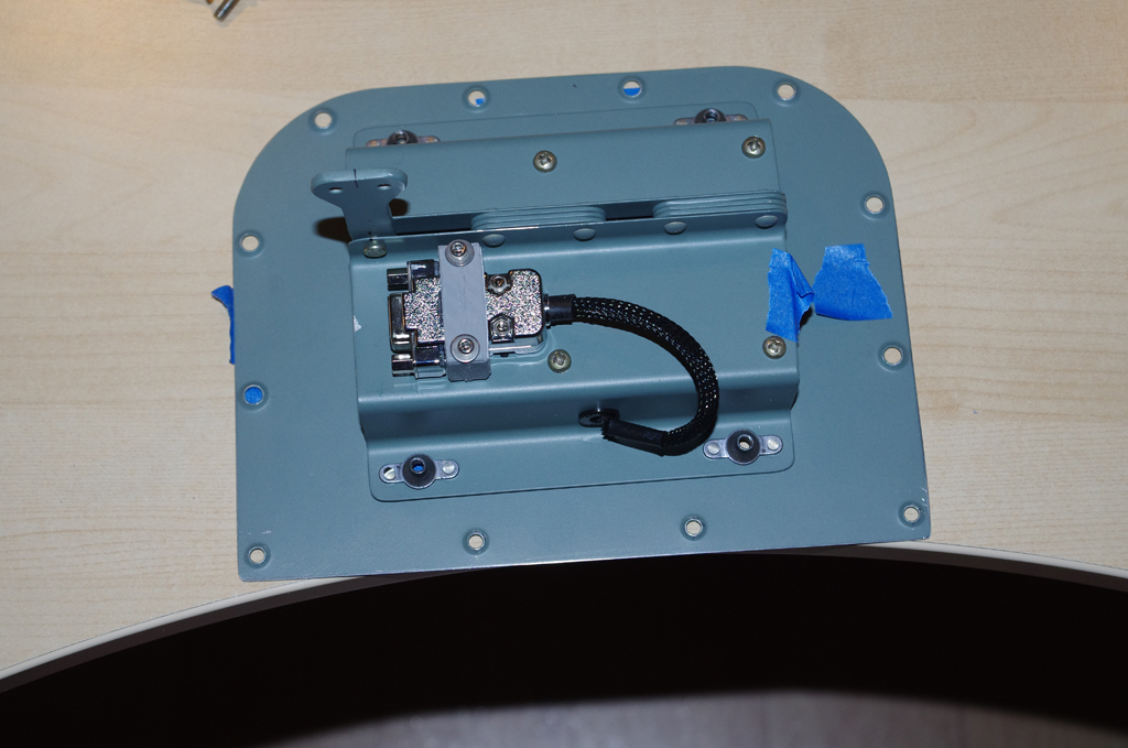
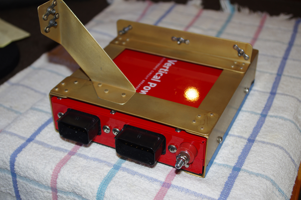
The previously free hanging Garmin GMU22 magnetometer cable was replaced with a custom rubber washer in 5/8″ hole drilled into the mounting bracket.  This new setup now provides secure fastening of the connector to the transmission wiring.


Custom brackets were fabricated to mount the two Garmin GA26C and one GA35 antennas under the fiberglass canopy above the overhead console tunnel. The cover plate will be painted the same interior colors after the shoulder strap and headphone mounts have been attached.  Note the GA26C antennas drive the Garmin G5 and PFD devices, while the GA35 provides WAAS-enabled signal for IFR flight with the certified GNC355 GPS/COM navigator.


Mounting the Garmin GSA28 autopilot servos to the rear bellcrank mounts required configuration of the movement arms.  The parts for the pitch servo are on the right. A diagram of the yaw servo parts are on the left.


The yaw servo attaches to the rudder cables via a special yoke.  This kit replaces the standard movement arm for the GSA28 servos.


In general throughout the whole build every wire was labelled with the same indications as shown on the AS-BUILT drawing.  The rear AeroLED Suntail wires were no exception.  These were pulled along with NAV2, AUX/COM, and ELT antennas, and pitch trim wire through the rear conduits to the tail.  The #2 Tefzel power and ground wires were then terminated with a 10 ton hydraulic crimper.


The terminated power wires connected to the PRI BATT and SEC BATT contactors.  The final wires were cable laced with a rubber fuel line as protection against chaffing on the floor and J-channel stringers.


With internal wiring completed a complete range of power on tests were again performed.  The CPC wiring, pitch/yaw servos and trims, battery contactors, flap motor, fuel pump, air vent, transponder, magnetometer, overhead lighting, GPS antennas and other components located within the core fuselage all passed initial functional testing.  While the majority of electrical connectivity has been successfully tested, the remote wing devices and engine monitoring sensors remain.


MISCELLANEOUS

Using leather punches I have started making custom washers from rubber or neoprene sheets of various thickness.  Here are two 1/4″ thick rubber washers for the floor light mounts.


Instrument Panel (5)

With the fuselage now initially primed, the installation of the instrument panel could begin.  As many connections as possible were first completed before insertion of the panel.

PREPARATIONS

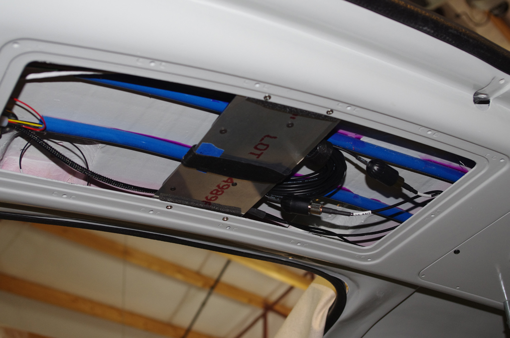
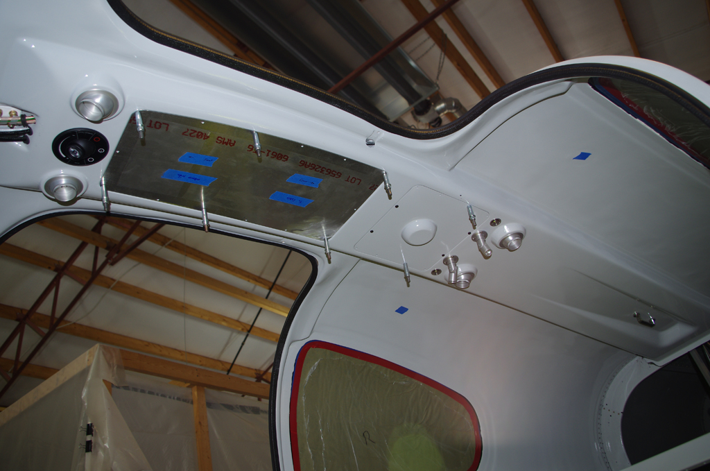
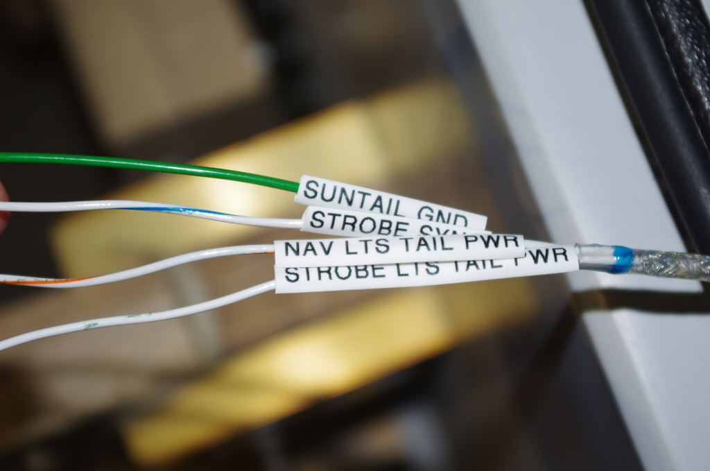
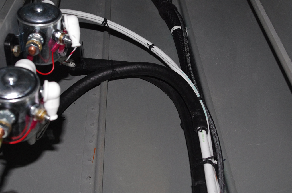
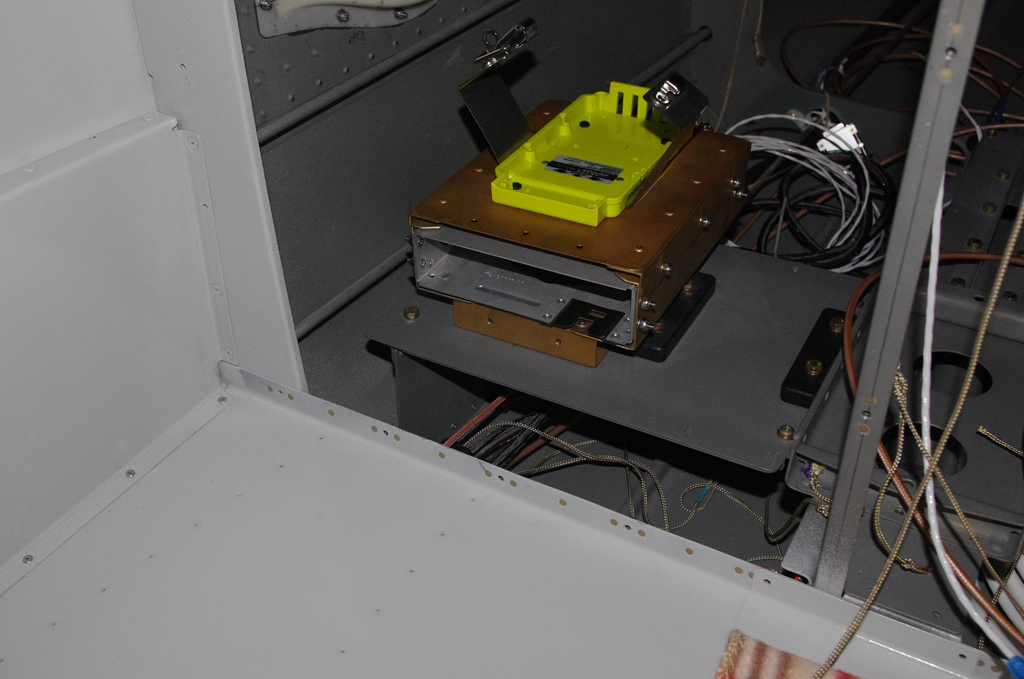
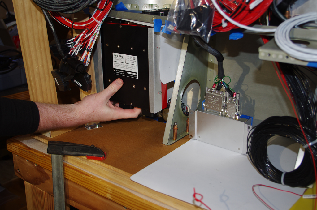
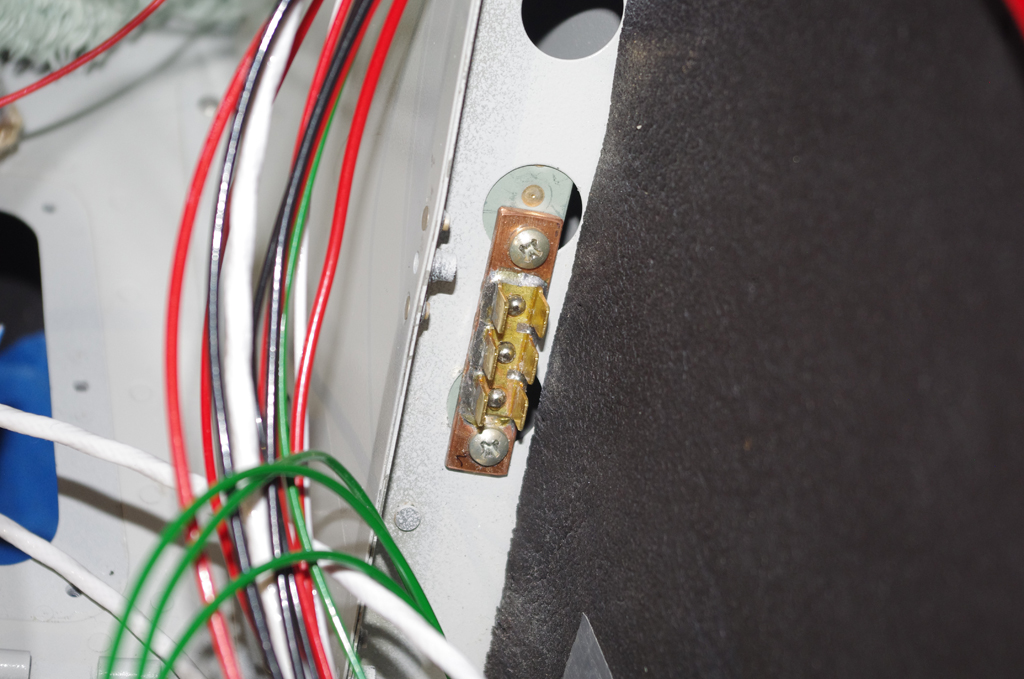
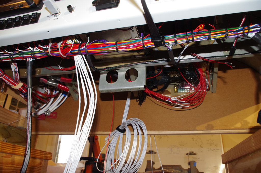
Here the GTX45R remote transponder / ELT brackets were installed behind the baggage bulkhead.  Termination of the major NAV/COM antennas with BNC or TNC connections behind the front sub-panel was also done.


ANL fuse and ammeter shunts were installed on the firewall side by Rich. The remote Airwolf oil filter bracket was bolted into place.  Inside, the forward cabin heating tube was attached in the center tunnel.  Many other items were added to the cockpit-side of the firewall – cross-tie contactor, ground blocks, GAD29 ARINC adapter, GEA24 engine monitor…


Initial wiring for B+C LR3C voltage regulators, VPX-PRO electronic circuit breakers, Guardian CO detector, floor lights, panel fans, etc. all were set to final configuration where possible.  The instrument panel was repacked in the original shipping crate for migration from my basement to the workshop for installation.


INSTALL

Rich and Tal unbox the instrument panel from the shipping crate, then hand to me for positioning under the dashboard.  Notice the PFD and MFD were removed to save weigh and allow easier access during installation.


Job done on the basic installation.  I had expected a tougher battle getting everything aligned, but was pleasantly surprised how well the panel fit on the first try.  In retrospect this was probably due to the time/effort/diligence applied to the mock-up and bench testing previous done in the basement workshop.


FURTHER CONFIGURATION AND INITIAL TESTING

With the panel now fastened in place, final attachment of wire bundles to VPX-Pro, voltage regulators, avionic stack, ground blocks, fuse holder… could occur.


Here was the first power-on testing performed with the panel inside the fuselage. Checks on basic functions were good, but a few tweeks were needed for control stick inputs, autopilot servos and trim motors.  All of these turned out to be simple repositioning of DSUB connector pins.


The G3X configuration pages show most of the main equipment details in their responses to CANBUS signals.  A few items have not yet been connected, so further testing will be performed as these devices are brought online.


Thumbs up on the radio COM1 and COM2 checks!  Now on to pulling and terminating more wire through the side cable chases.


Instrument Panel (4)

Bench testing the instrument panel required full connectivity of the ground and power wires, antenna connections and attachment of remote devices like the GSA28 autopilot servos. This is because the CANBUS wiring of the G3X system will not function properly without the right bus terminations.

Both the pitch and roll servos contain power and sensing wires.  Standard DB9 connectors and shells were made up for each device.


Custom brackets for the DSUB shells were designed using Blender, exported to .STL format, sliced, then 3D printed in nylon on a Prusa i3 MK3S printer. The resulting connections are very strong and should perform well in the plane. For the bench test they were provisionally connected straight to the instrument panel wiring (i.e. no breakout points or extensions).


AeroLED VX taxi, land and wig-wag light switches were tested on the bench. The picture at right shows the underside of the instrument panel wiring, especially where the grounding tabs and fuse block are located.  While there are many wires in a small space, the organization seems good.  At least now after familiarization with the wiring harness I can track down any wires with the help of an updated diagram.


The test rig was powered through the ANL fuse / shunt holder connected to the firewall pass-through terminals.  The amperage sensing wires are not shown in the left photo, but were used during the G3X configuration and test.  On the right are the bench test setup.  Note the control sticks are not yet configured here.


This photo shows the first activation of the completed bench test setup! The control sticks are attached and almost all devices were powered up.  Tests of all connected switches, avionics, and devices were successful. The GMU22 magnetometer and the GSU25 AHARS unit were displayed in the configuration page, but were not calibrated as specialized equipment is required.  There were a few devices not configured at all for the test, such as flap motors, pitot heat and the CO detector. A complete set of tests will be performed later in the final installation.  With the test setup the overall idle state electrical consumption was 7.2 Amps.


These screen shots from the G3X Configuration Mode show the basic system information and detected devices. The test scope for this stage of the project was acceptable and the results were good.  I feel much more comfortable with the avionics and electrical systems, so now on to more fuselage assemblies.


Instrument Panel (3)

Progress was made over the holidays by taking advantage of the social distance rules enforced in our area to focus on individual work.

The sub-panel was modified to accept the VPX-Pro electronic circuit breaker box.  Here the raw opening was cut, followed by layout of the rivet and fastener holes for a backing plate.


The final holes for the VPX opening are drilled.  The blue tape shows the future location of the primary and secondary voltage regulators (B&C LR3C-14).  The untreated backing plates on the right picture were clecoed for test fits.


The backing plates and mounting brackets were prepared for the standard alodine treatment, which consists of scuff, degrease, acid wash, rinse, alodine dip, rinse again and hang to dry.


The alodined ANL fuse/shut brackets are on the left.  At right are the completed brackets painted Boeing 707 Gray and bolted together.  Notice the copper bridge used between the ANL fuse and shunt. The raw bus bar stock of 1/8″ x 1/2″ copper is rated for 250Amps, plenty for this location. The bracket will eventually be mounted on the engine side of the upper firewall.


The cockpit side of the firewall will mount the GAD29 ARINC Adapter (left) and the GEA24 Engine Monitor devices.  The GEA24 bracket also serves as the mount point for the B&C GB24/48 ground blocks.


Firewall penetrations for the terminal posts were supported by a backing plate. The nylon attachment point will secure the #2 wire from the GB24/48 ground block to the batteries which are located in the rear behind the baggage bulkhead.


The finished VPX-Pro mounting bracket fits perfectly in the corresponding cutout in the sub-panel (shown above).


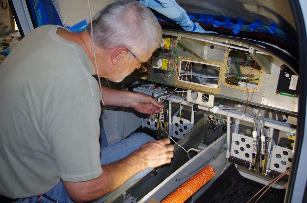
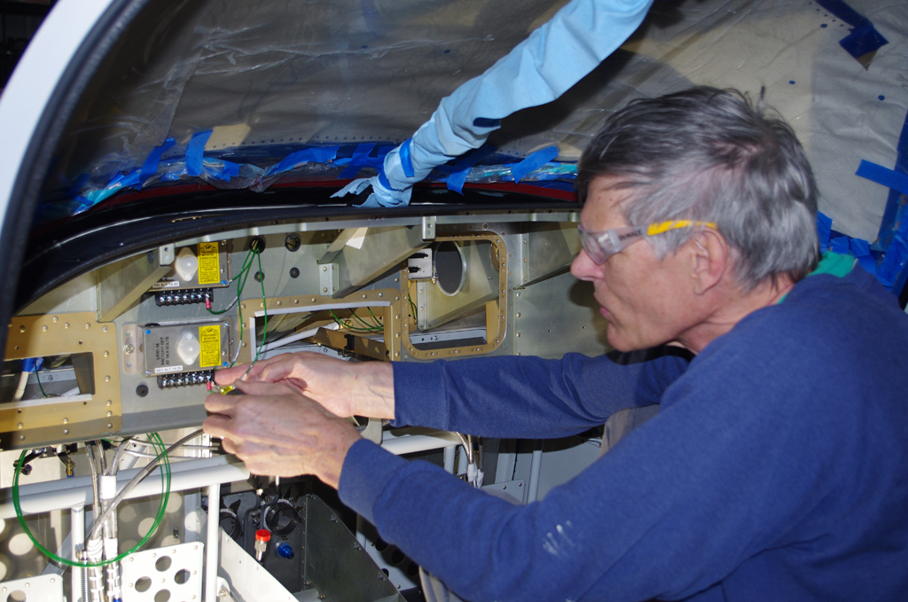
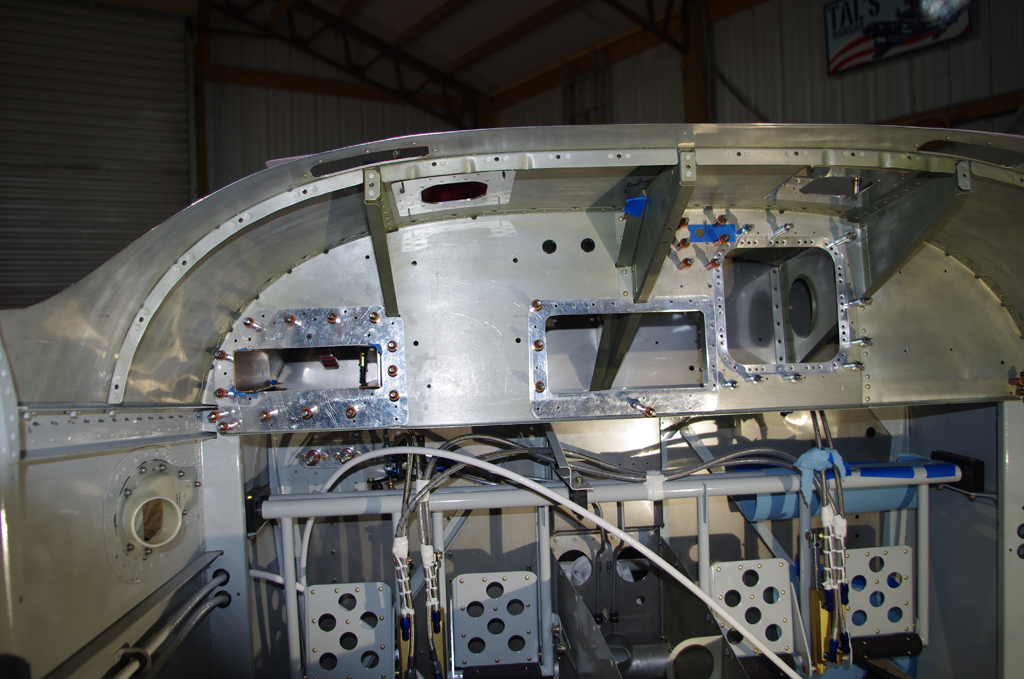
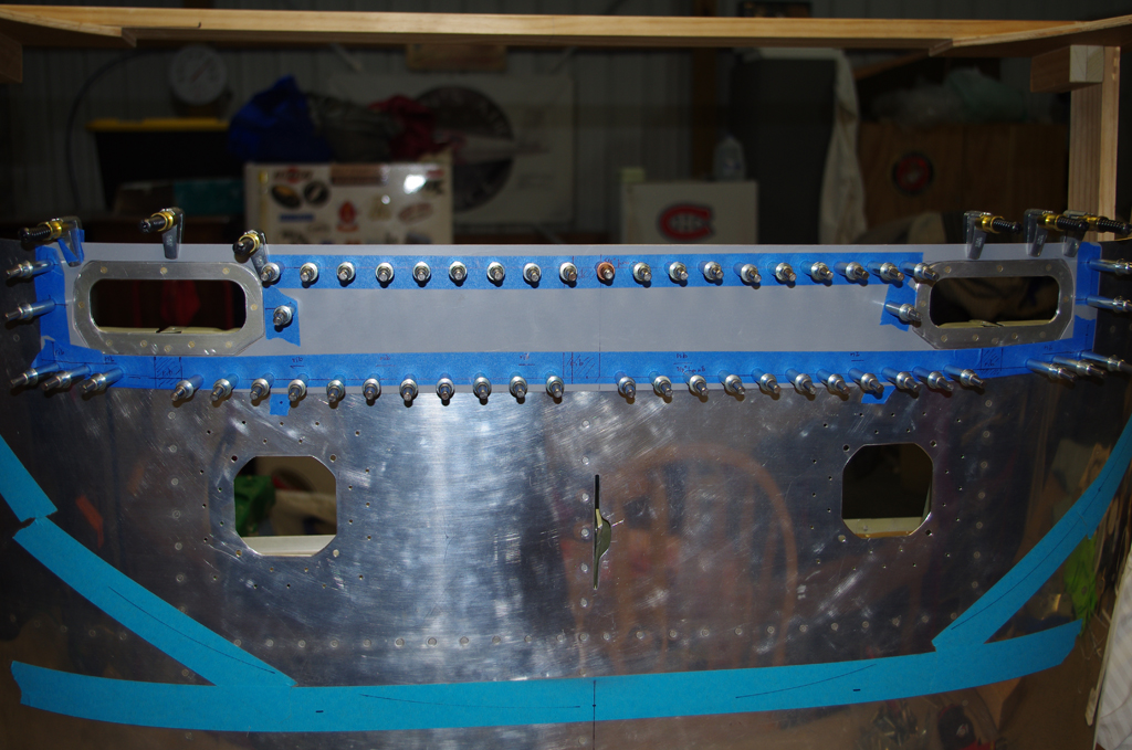
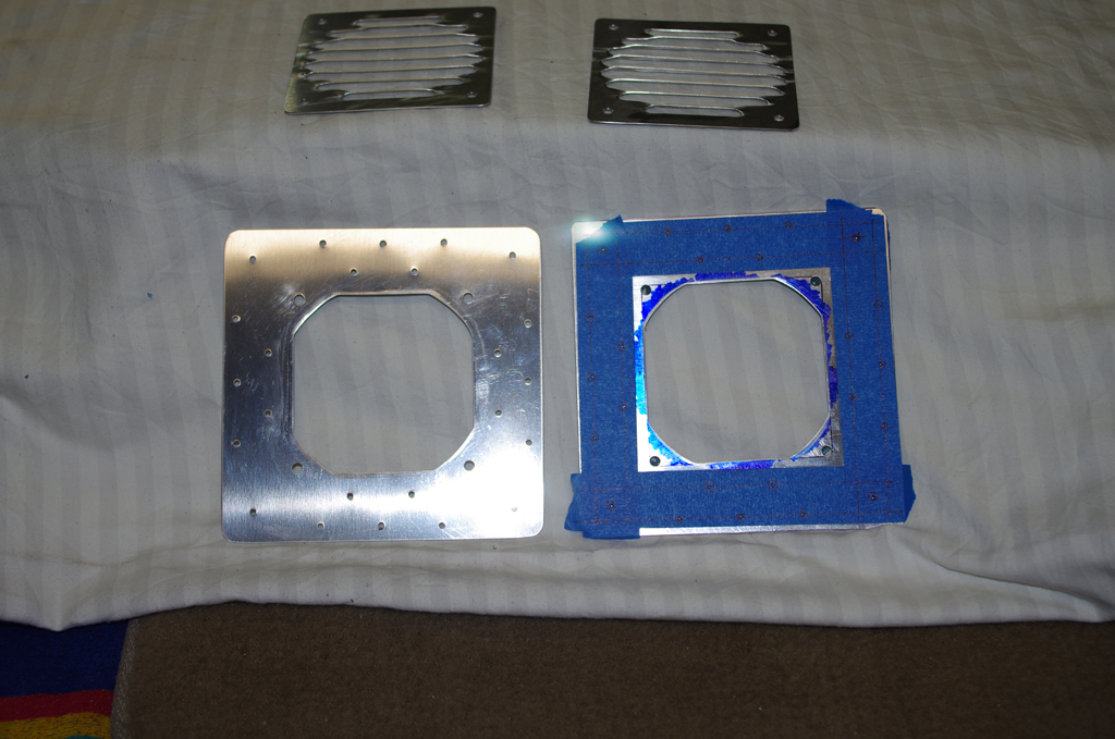
The alodined backing plates were clecoed to the sub-panel prior to riveting.  The right photos shows #8 nutplates being riveted onto the inspection port backer.


The inspection port backer riveted in place as seen from in front and behind the sub-panel.


A reinforcement plate was fabricated to strengthen the VPX-Pro cutout hole and provide a mounting point for Adel clamps to secure cabling.  On the right the DRDT-2 was used to dimple the dashboard for the panel fan backers.


The panel fans will be 80mm brushless computer fans with a high cfm ratng.  They are very loud at full power, but speeds will be adjustable for correct cooling by a rheostat on the panel.


The dashboard skin is very thin (.032″) near the handle grips.  To help strengthen this area for routine operations, a fiberglass reinforcement piece will be added.


The primary and secondary circuits from the rear mounted batteries to the firewall terminals use #2 wire.  The terminals are also attached to a cross-tie contactor – the single joint connection point between the two separate buses.  A test fit of a tee-shaped boot shows how the terminal posts will be insulated.


On the engine side of the firewall the terminal posts connect to the starter contactor with #2 wire, and to the shunts with #6 wire.  The right photos shows the #2 ground wire on the cockpit side bolted to the GEA24 mounting bracket.


The large #2 battery wires were crimped with a YQK-300 16ton Hydraulic Crimper. At the recommendation of electrical experts in the community the terminal lugs were lightly soldered at the tips just to secure an electrical connection to the wire.  The solder should not wick into the flexible wire area as the heavily crimped section should be cold fused together to prevent penetration. At least that is the theory…


Completed terminal wires were heat shrink wrapped for insulation and protection.


Because the default wire for GTP59 Outside Air Temperature probe arrived too short to reach an appropriate mounting location in the left wing, the default termination to the GSU25 ADAHRS unit needed to be replaced with a longer wire. Prior to the re-pinning effort, the DB15 configuration was photographed.  The extracted J252 Pins 1,2,3 were then replaced with new wire.


A common termination point for aircraft ground wires near the instrument panel provides a direct, high quality electrical pathway back to the batteries.  In addition, the colocation of labelled wires will help future troubleshooting activities.


The sub-panel inspection port serves a dual function as being the mounting location for the secondary bus fuse block (Bussman 17512-24).   On the completed fuse block ‘dumb’ devices (panel fans, floor lights, overhead lights, etc.) are bench tested with a 14.4V switching power supply. So far, so good.


Next steps are checking wire runs and functions on the main G3X devices and avionics.

Instrument Panel (2)

The last few weeks have focused on fabricating backing plates and mounting brackets for miscellaneous devices related to the instrument panel and dashboard configurations.

The rheostat controlling the rear air vent servo was purchased from AeroSport Products some time ago.  The instrument panel was provided by SteinAir without this unit installed.  However, Nick from SteinAir was kind enough to supply an extra knob exactly like the others on the panel – free of charge.  The post on the AeroSport unit was quite a bit taller than the stock SteinAir units, so shortening was required.  The final outcome looks great.


Here is a view of the installed air vent rheostat viewed from under the instrument panel.


These two pictures show provisional placement of the VPX circuit breaker box and the GAD29 ARINC adapter.  These test locations were used to indicate any last minute interferences and/or cable runs to the units before actually punching holes in the sub-panel or the firewall.


A 2″ square tube, .063 wall thickness was cut in to on a 1953 vintage Delta 28-207 bandsaw, then used to build a holding cradle for the VPX. Final placement of the unit will be fitted with the dashboard clecoed onto the forward  fuselage assembly. (more pictures on this in a later post).


Holes in the dashboard for panel fans require reinforcing backers.  The Van’s recommendation is a backing plate at least on inch wide, the same thickness as the original material, and with rivets between no further than 1″ separation and in a row 1/2″ apart.  These plates were designed to meet those specs.


Once fabricated the panel fan backers were measured for location, then the holes punched accordingly in the upper dashboard.


This picture shows the interim state of both panel fan holes.  Next steps are dimple the parts for 3/32 rivets, alodine the backers, then rivet into place.


The left photo shows the location and holes for the firewall side ground terminal. On the right is the backing plate for the Airwolf remote oil filter.


Here is the final location of the starter contactor, with holes drilled through the firewall. The bolts will serve a dual purpose by fastening the cross-tie contactor on the cockpit side.  The right photo shows the ANL fuse/shunt fixture also in its final location.


SB-0002

Vans just recently issued a service bulletin about checking for cracks in the lower rudder attachment bracket on the vertical stabilizer.  Since my plane is still under construction, I proceeded to remove the original brackets now and replaced with the SB parts.


Instrument Panel (1)

The instrument panel arrived from Stein Air this week.  They did an excellent job on the panel cutout, painting, engraving, avionics installation, and wire lacing.  I am thrilled to have this element in-house, as full scale configuration can now proceed on the dashboard and firewall.

Unpacking the shipment crate…


This design is fairly simple, intended for a low-time pilot like me.  The G3X system has two 10″ displays with more information available than ever possible with steam gauges. This airplane has a complete glass cockpit, which includes a dual battery, dual bus electrical system with independent alternators and a cross-tie switch.  The G5 provides basic redundancy and power separated from the main flight displays.  One Surefly SIM6L electronic ignition will complement the standard Slick magneto.


Maybe too many rocker switches were installed, since most functions could be activated from the touch screen displays.  However, I like tactile devices for better feel and certainty in rough/bumpy conditions.  The normal shutdown sequence will be from right-to-left.  Rheostats provide variable power to various lights, fans and vents.


The right panel has an ELT remote switch (to be installed), CO alarm for carbon monoxide monitoring, and a toggle switch for an alternate static air source. There are also two USB charging units on the panel, plus a 1/2″ drilled hole for later mounting of an iPad or iPhone.


The intermediate sub-panel on the dashboard is approximately 9″ behind the main panel.  Unfortunately, the GNC355 GPS and GNC 255 communications modules are deeper.  This required cutting out the sub-panel to accommodate the depth of the avionics.  Fortunately I had created a 3D model which laid out the orientation.  As a result he structural angled rib did not need relief.


Next on the TODO list are reinforce the openings, then build mounting brackets for the VPX Pro electronic circuit breaker, GEA 24 engine monitoring system, GAD 29 ARINC adapter, and cross-tie contactor.  The CO detector unit and the two B&C LR3C voltage regulators will be mounted flat on existing panel surfaces.  All these locations were simulated on the 3D CAD model, for which I will provide details in a later post.