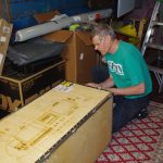
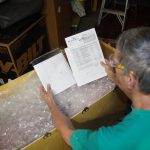
The instrument panel arrived from Stein Air this week. They did an excellent job on the panel cutout, painting, engraving, avionics installation, and wire lacing. I am thrilled to have this element in-house, as full scale configuration can now proceed on the dashboard and firewall.

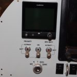 This design is fairly simple, intended for a low-time pilot like me. The G3X system has two 10″ displays with more information available than ever possible with steam gauges. This airplane has a complete glass cockpit, which includes a dual battery, dual bus electrical system with independent alternators and a cross-tie switch. The G5 provides basic redundancy and power separated from the main flight displays. One Surefly SIM6L electronic ignition will complement the standard Slick magneto.

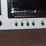 Maybe too many rocker switches were installed, since most functions could be activated from the touch screen displays. However, I like tactile devices for better feel and certainty in rough/bumpy conditions. The normal shutdown sequence will be from right-to-left. Rheostats provide variable power to various lights, fans and vents.
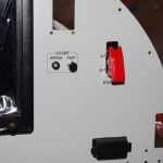 The right panel has an ELT remote switch (to be installed), CO alarm for carbon monoxide monitoring, and a toggle switch for an alternate static air source. There are also two USB charging units on the panel, plus a 1/2″ drilled hole for later mounting of an iPad or iPhone.

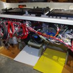 The intermediate sub-panel on the dashboard is approximately 9″ behind the main panel. Unfortunately, the GNC355 GPS and GNC 255 communications modules are deeper. This required cutting out the sub-panel to accommodate the depth of the avionics. Fortunately I had created a 3D model which laid out the orientation. As a result he structural angled rib did not need relief.
Next on the TODO list are reinforce the openings, then build mounting brackets for the VPX Pro electronic circuit breaker, GEA 24 engine monitoring system, GAD 29 ARINC adapter, and cross-tie contactor. The CO detector unit and the two B&C LR3C voltage regulators will be mounted flat on existing panel surfaces. All these locations were simulated on the 3D CAD model, for which I will provide details in a later post.
