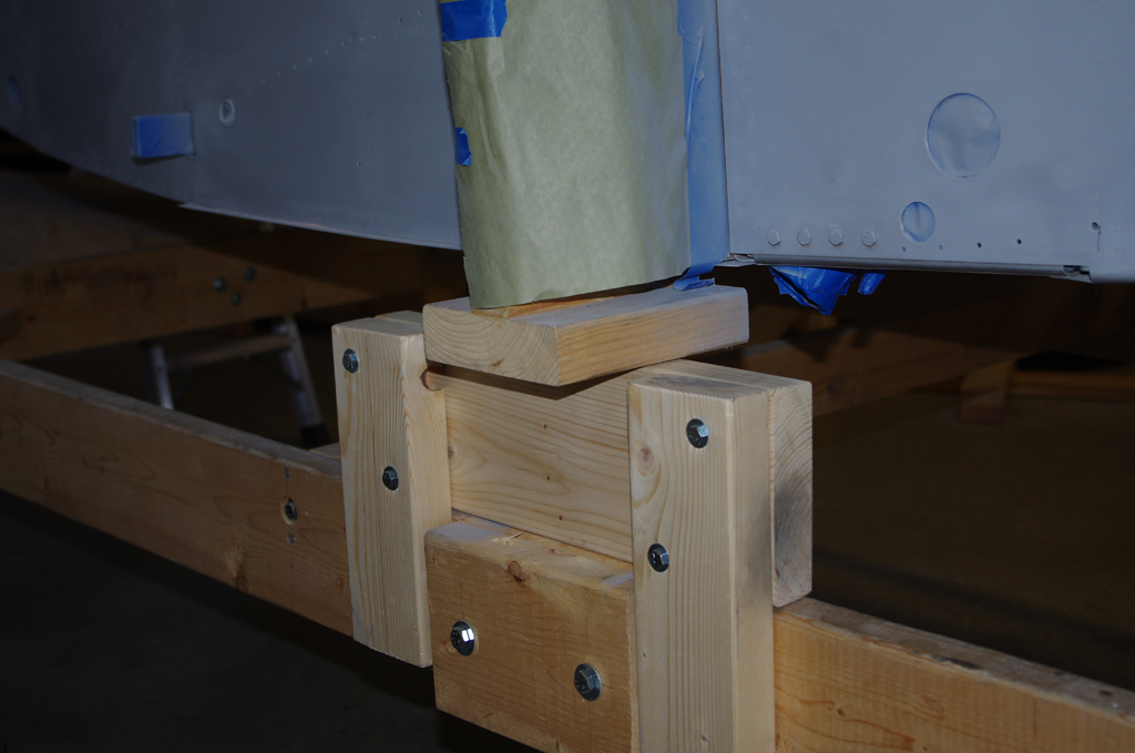
With the fuselage now initially primed, the installation of the instrument panel could begin. As many connections as possible were first completed before insertion of the panel.
PREPARATIONS
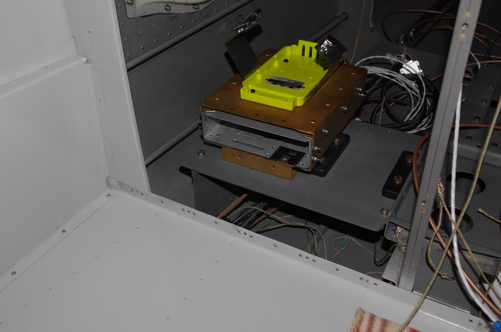
 Here the GTX45R remote transponder / ELT brackets were installed behind the baggage bulkhead. Termination of the major NAV/COM antennas with BNC or TNC connections behind the front sub-panel was also done.

 ANL fuse and ammeter shunts were installed on the firewall side by Rich. The remote Airwolf oil filter bracket was bolted into place. Inside, the forward cabin heating tube was attached in the center tunnel. Many other items were added to the cockpit-side of the firewall – cross-tie contactor, ground blocks, GAD29 ARINC adapter, GEA24 engine monitor…
 Initial wiring for B+C LR3C voltage regulators, VPX-PRO electronic circuit breakers, Guardian CO detector, floor lights, panel fans, etc. all were set to final configuration where possible. The instrument panel was repacked in the original shipping crate for migration from my basement to the workshop for installation.
INSTALL
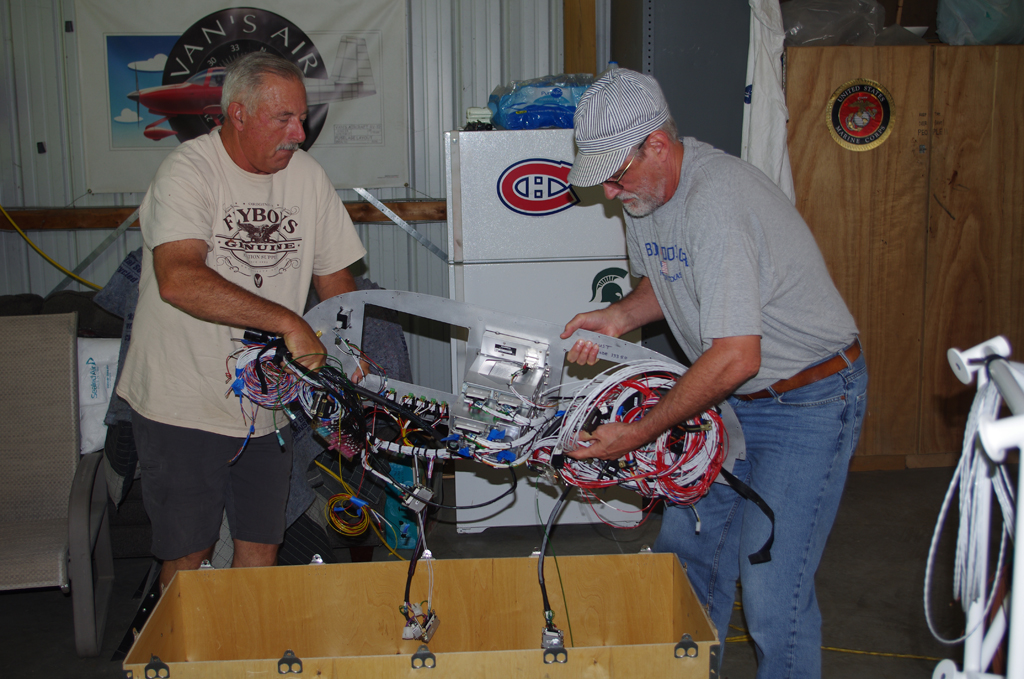
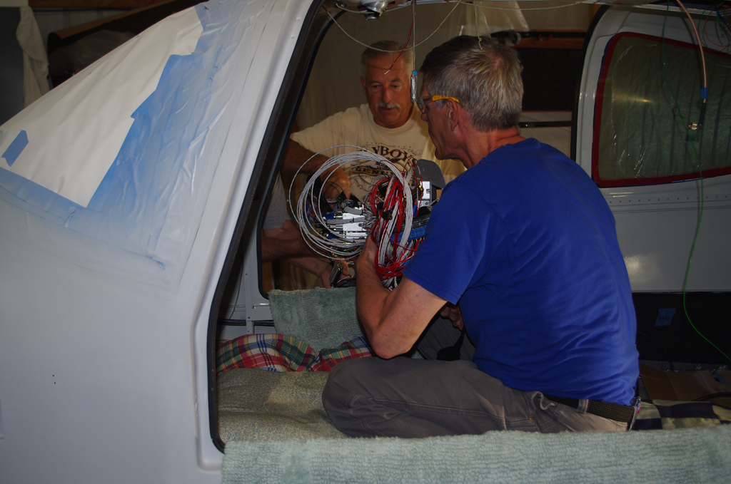 Rich and Tal unbox the instrument panel from the shipping crate, then hand to me for positioning under the dashboard. Notice the PFD and MFD were removed to save weigh and allow easier access during installation.
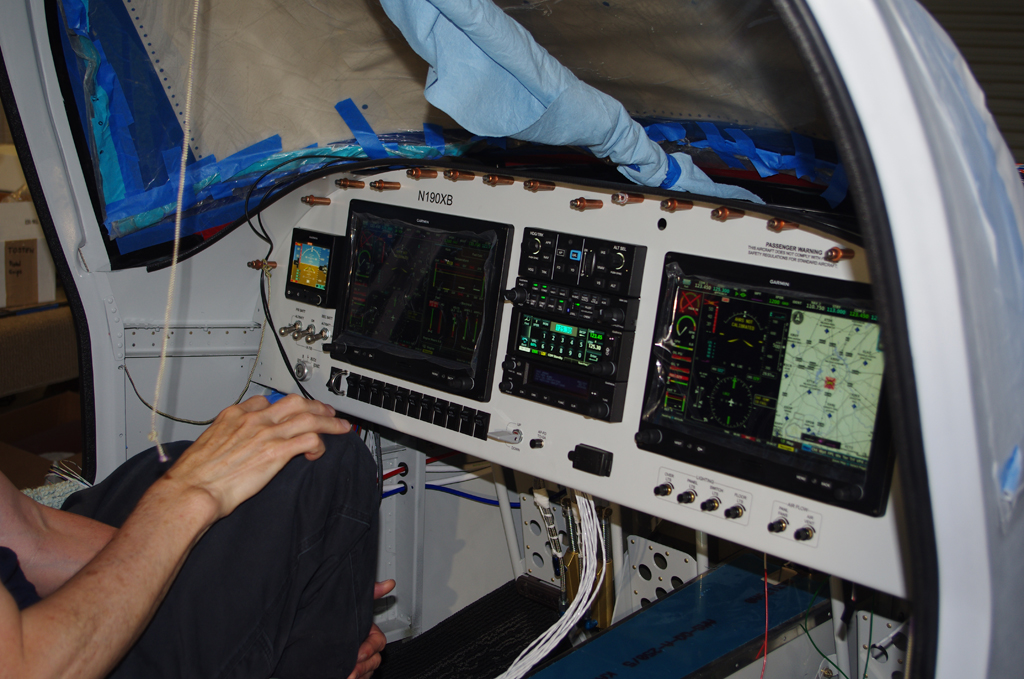
 Job done on the basic installation. I had expected a tougher battle getting everything aligned, but was pleasantly surprised how well the panel fit on the first try. In retrospect this was probably due to the time/effort/diligence applied to the mock-up and bench testing previous done in the basement workshop.
FURTHER CONFIGURATION AND INITIAL TESTING
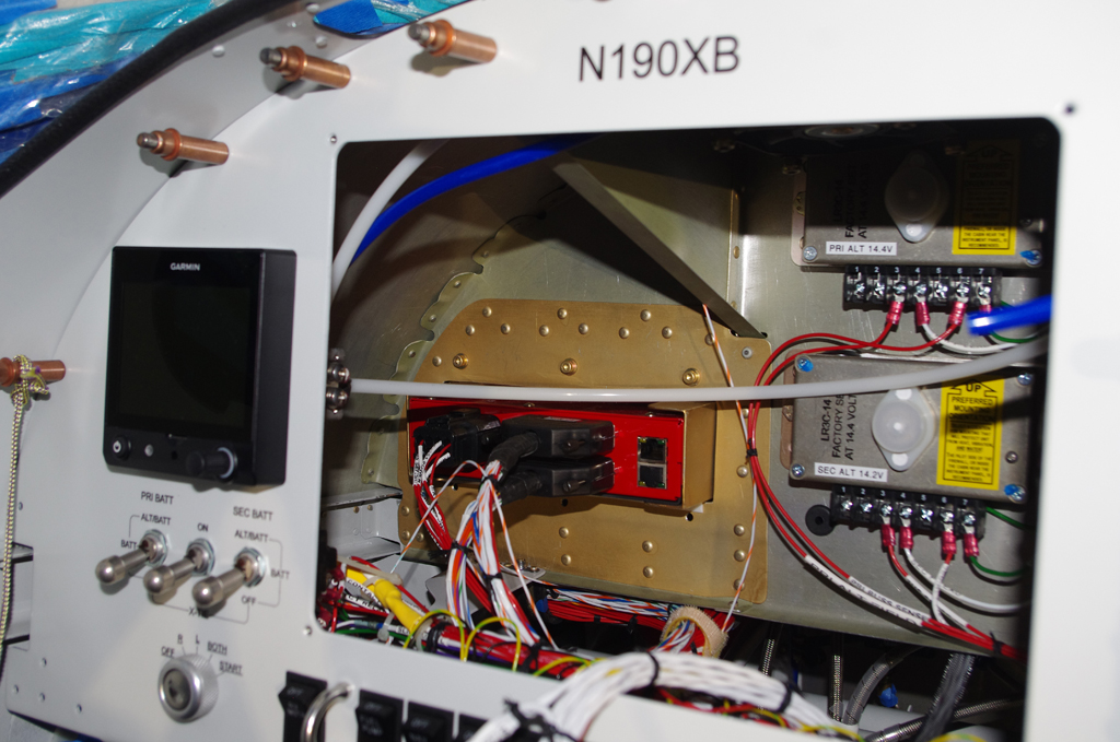

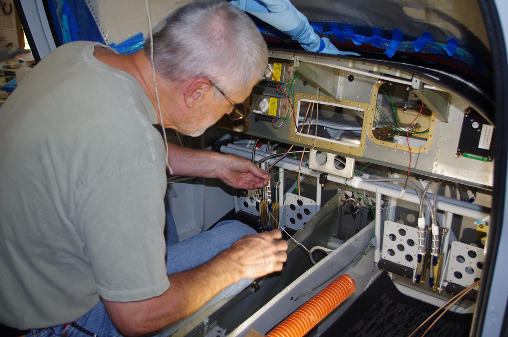
 With the panel now fastened in place, final attachment of wire bundles to VPX-Pro, voltage regulators, avionic stack, ground blocks, fuse holder… could occur.
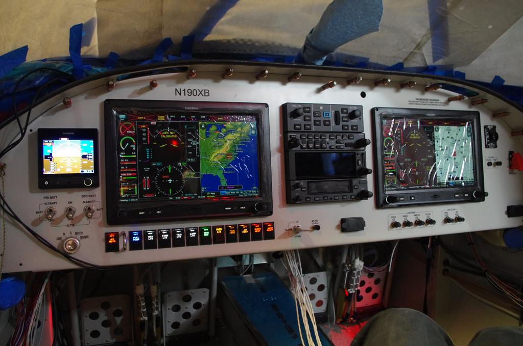
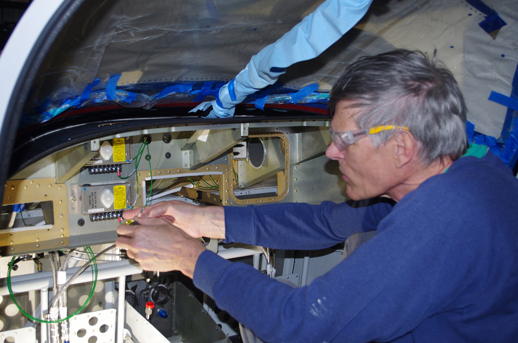
 Here was the first power-on testing performed with the panel inside the fuselage. Checks on basic functions were good, but a few tweeks were needed for control stick inputs, autopilot servos and trim motors. All of these turned out to be simple repositioning of DSUB connector pins.

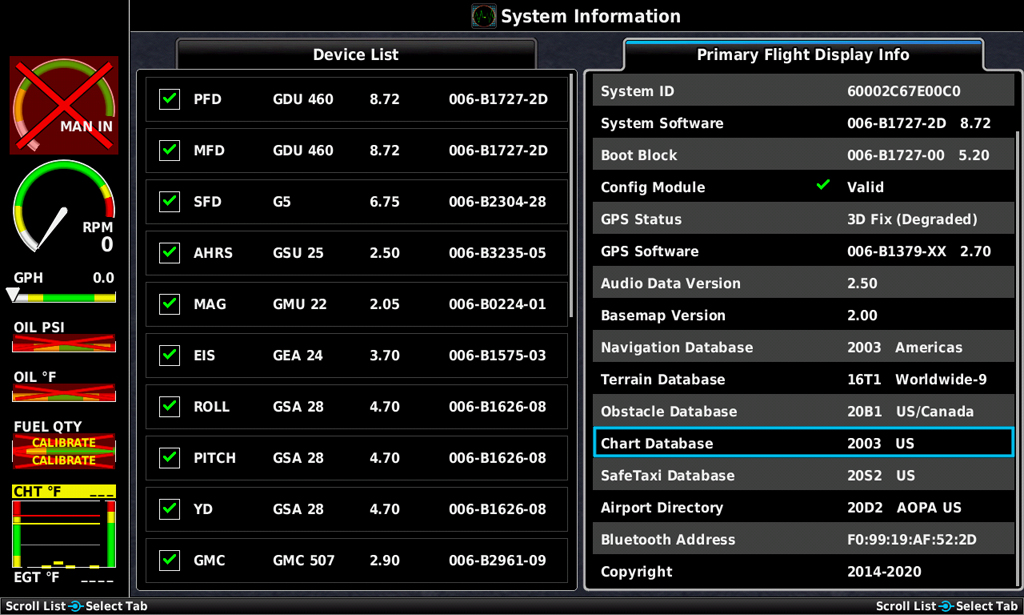 The G3X configuration pages show most of the main equipment details in their responses to CANBUS signals. A few items have not yet been connected, so further testing will be performed as these devices are brought online.
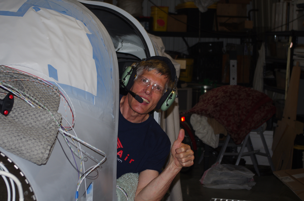 Thumbs up on the radio COM1 and COM2 checks! Now on to pulling and terminating more wire through the side cable chases.