Monthly Archives: January 2016

You are browsing the site archives by month.

Step/Antenna Inspection Ports (3)

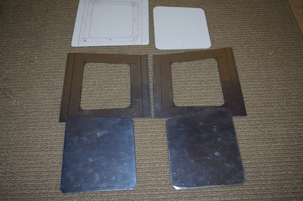
This weekend was about prime and rivet the inspection backers to baggage floor, then position and drill for the antenna plates for the right side installation.

IMGP6226IMGP6228IMGP6234

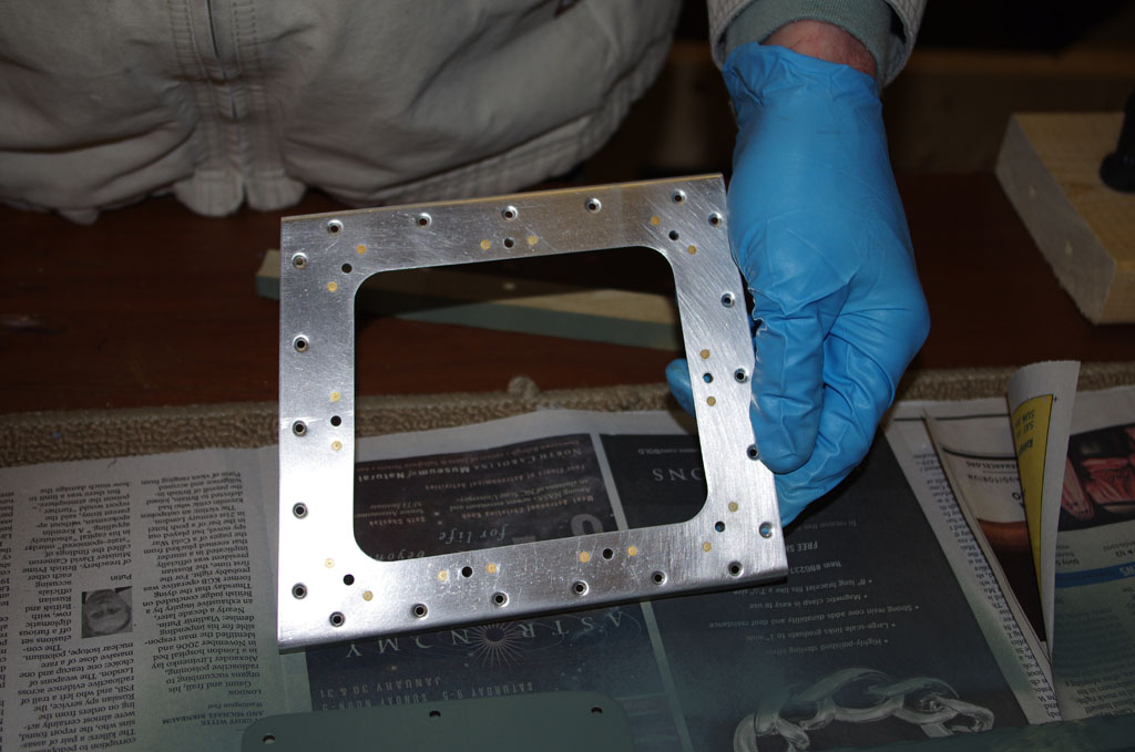
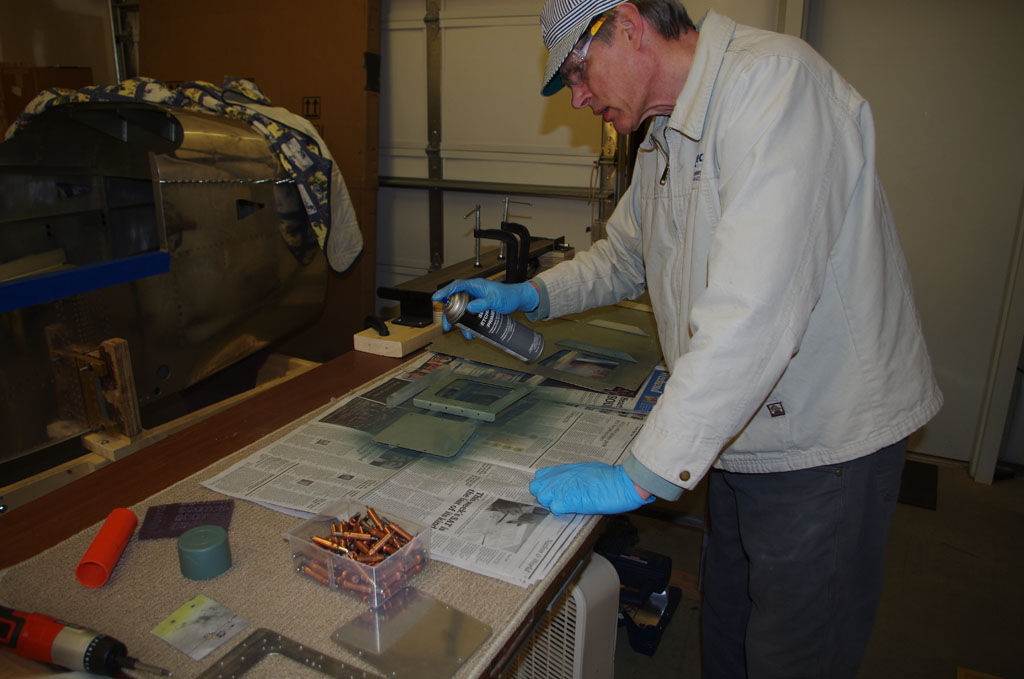
Add nutplates and prime with SEM aerosol can.


IMGP6239IMGP6241
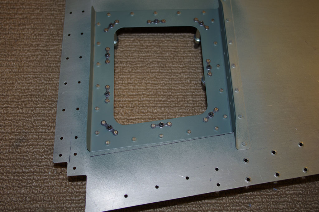
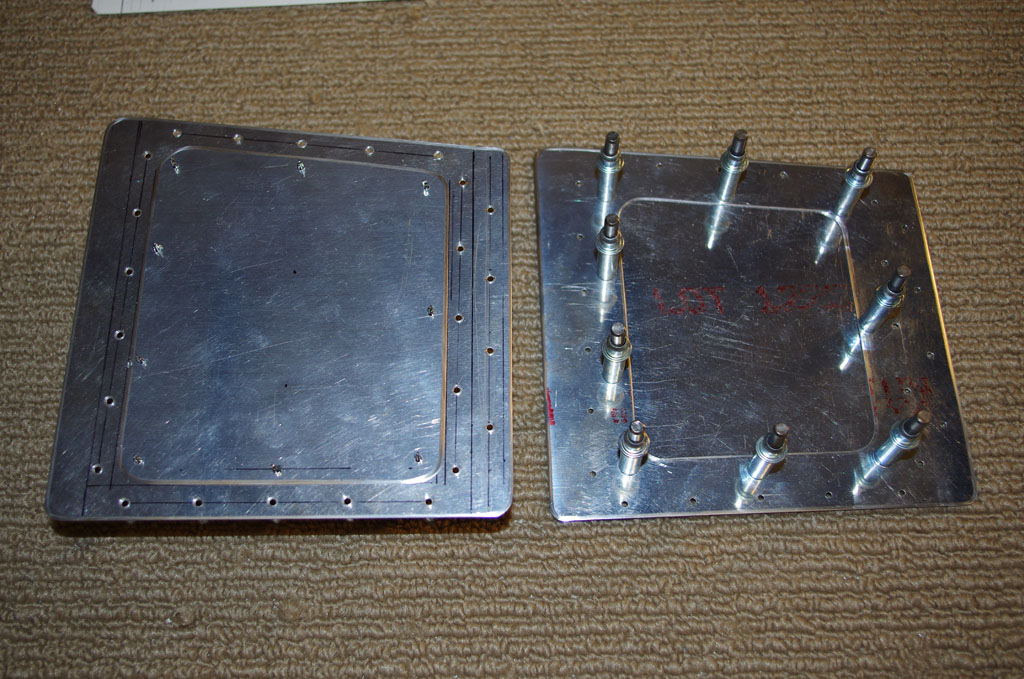
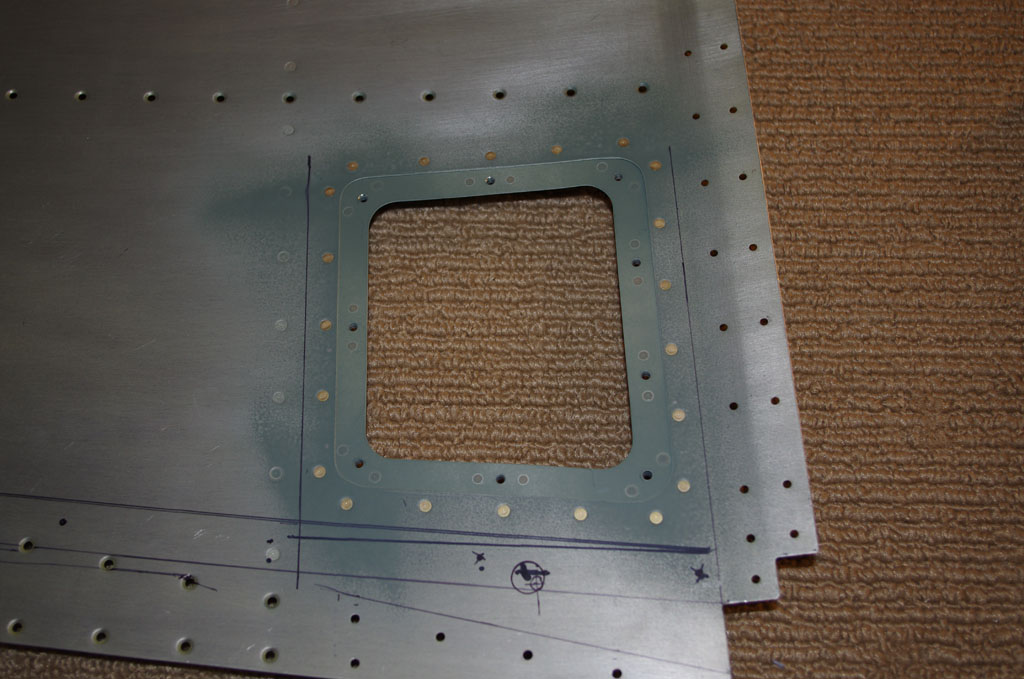
Top and bottom sides after completion of riveting.


IMGP6242
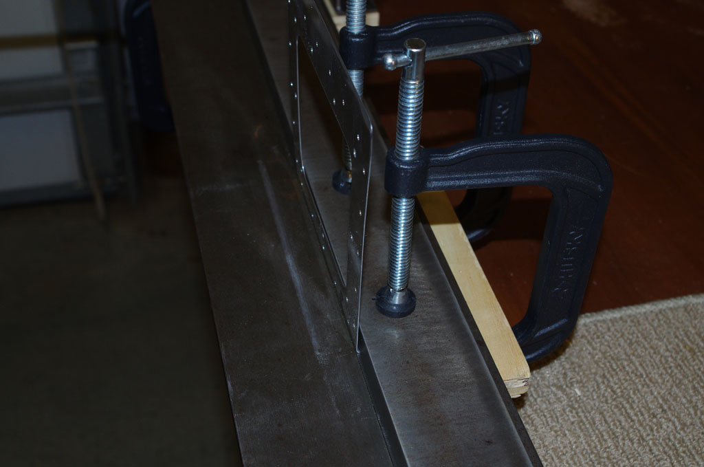
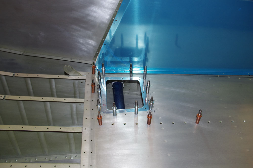
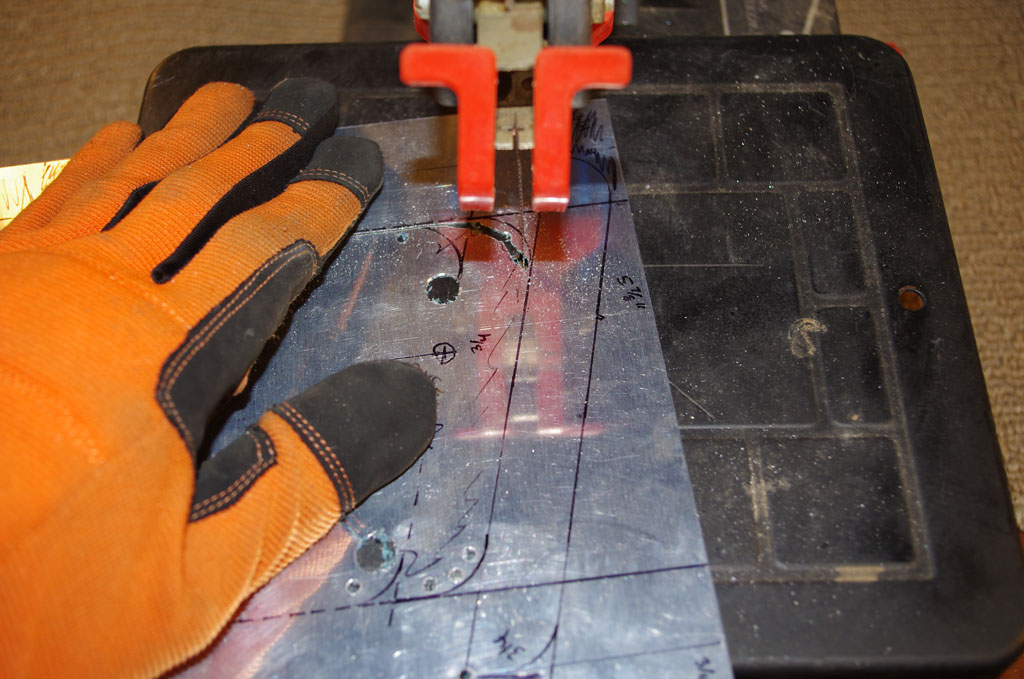
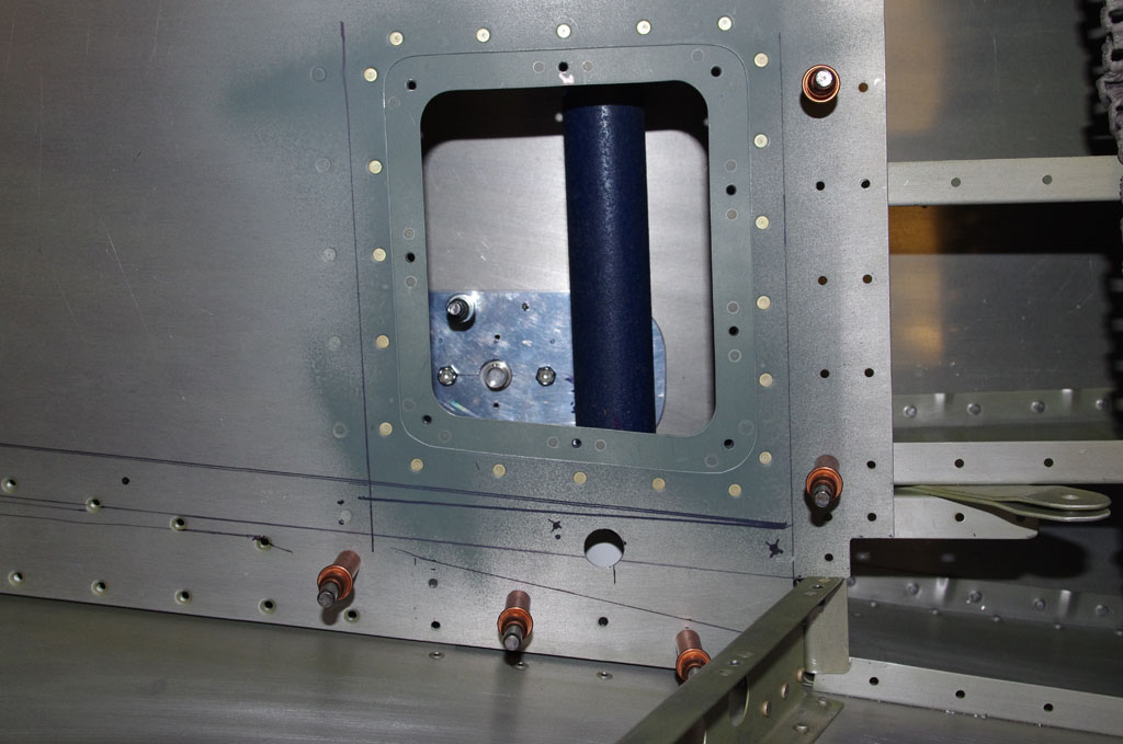
This angle in this photo shows the 9/16″ hole drilled through the baggage floor to allow later access to the step bolt.


IMGP6243IMGP6244
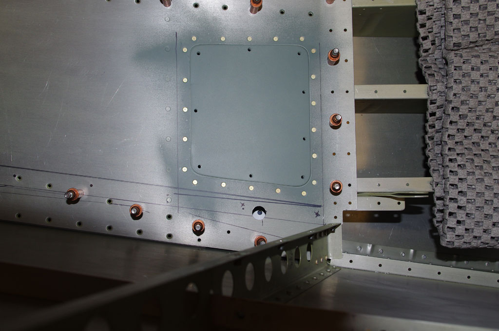
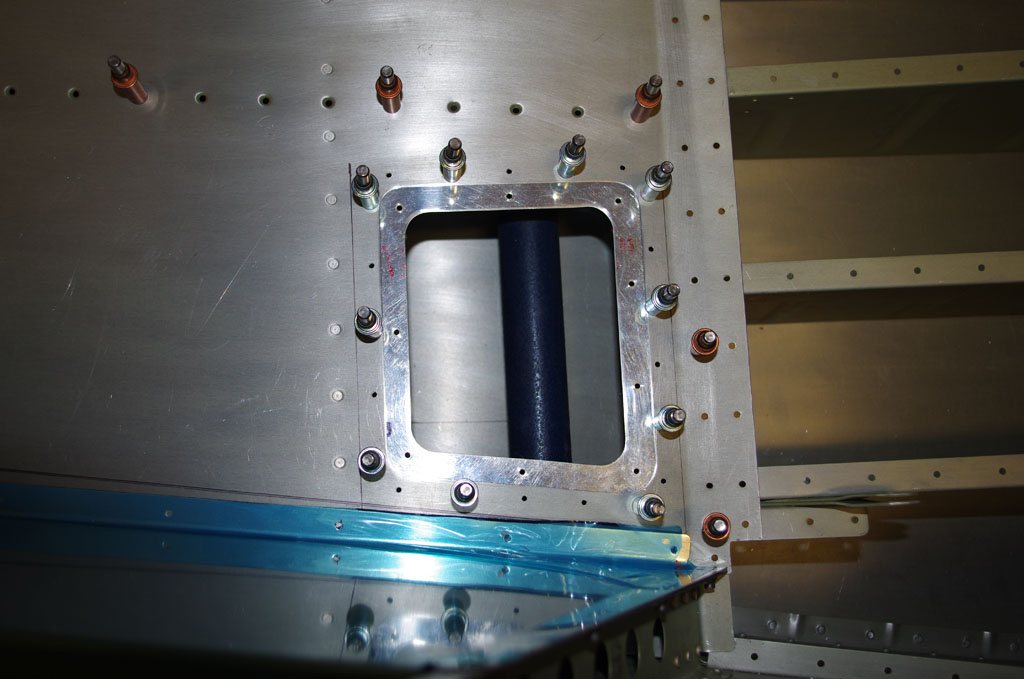
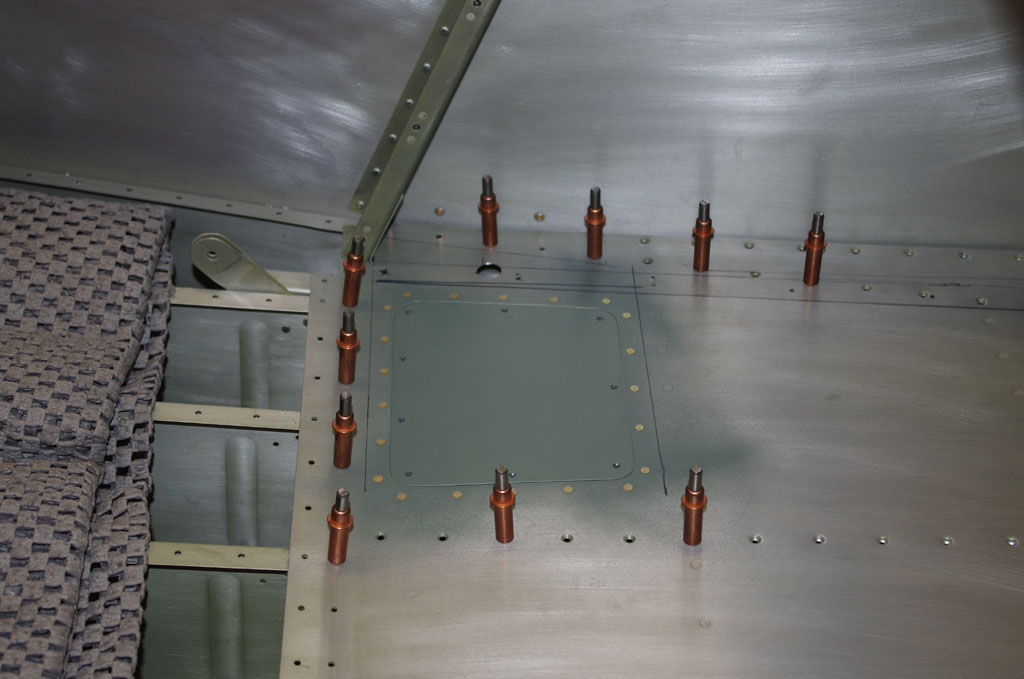
Two photos of the inspection plate in position.


IMGP6249IMGP6252
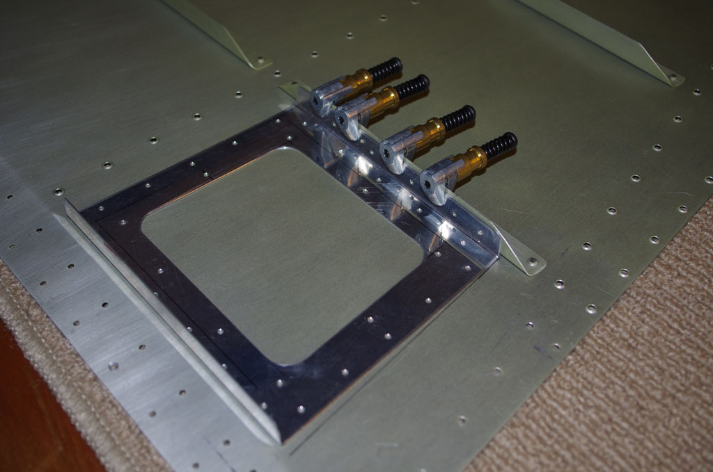
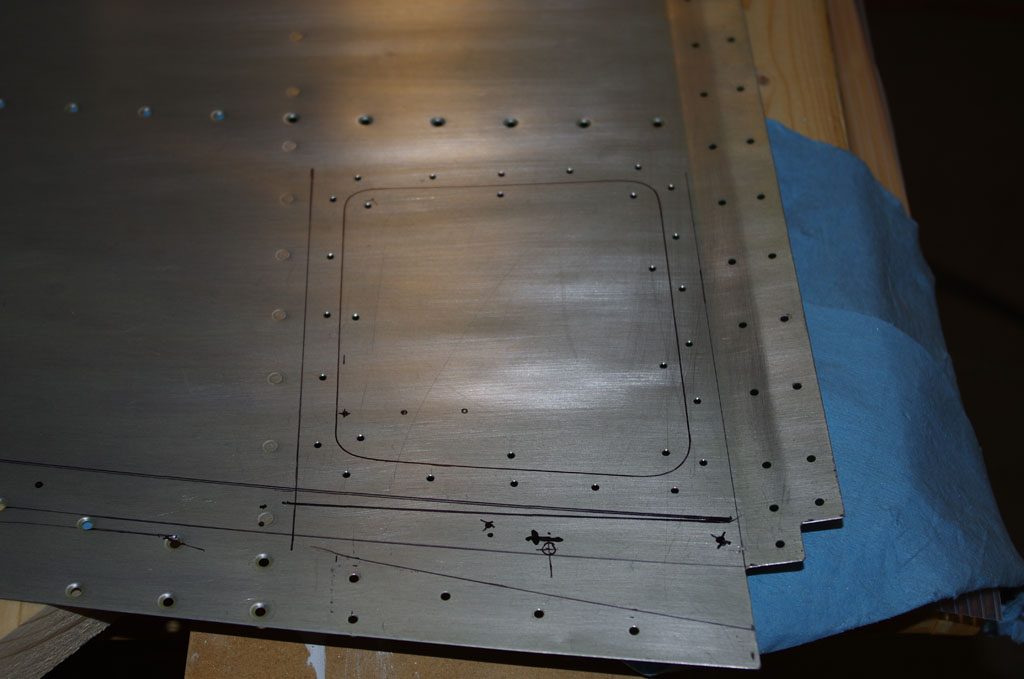
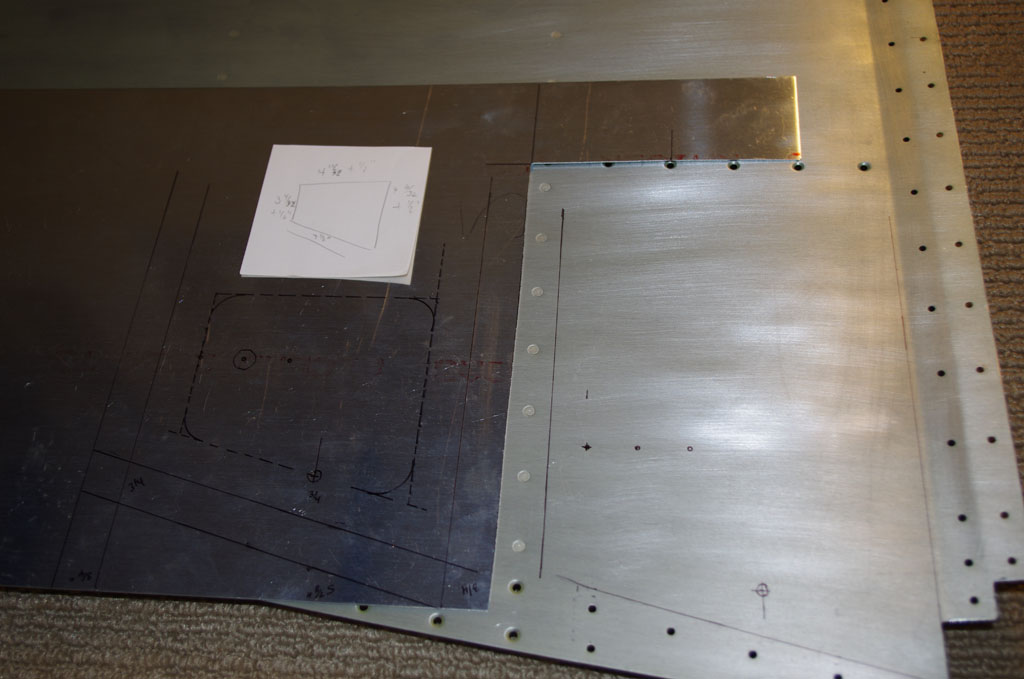
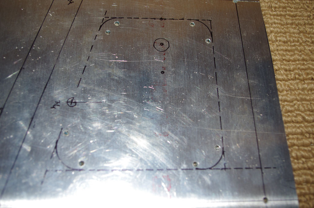
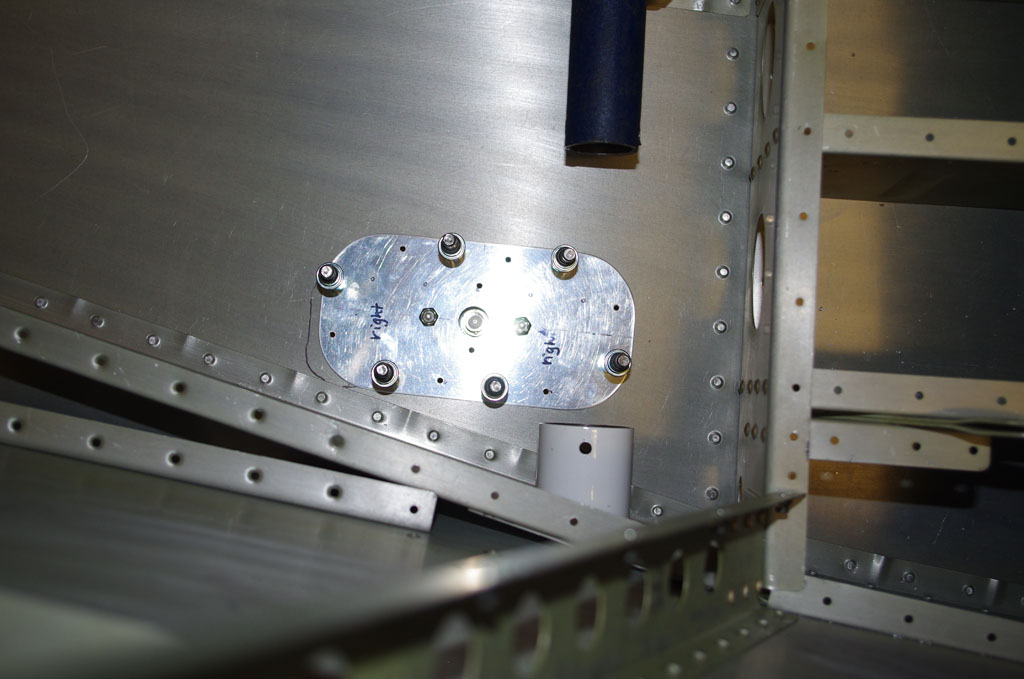
Antenna plate for ADSB receiver drilled and clecoed in place.


IMGP6253This angle shows the antenna backer access. Getting to the coax connector and the two hold-down nuts for the antenna itself should be straightforward with this configuration.


Step/Antenna Inspection Ports (2)

These ports haven taken a long time to fabricate, basically because most of the work is being done by hand and I am quite slow with a file.  This results are usually decent for me with this method.

IMGP6198IMGP6207These are the roughed out plates and backers in the left photo after hand shaping and polishing. On the right are both set after initial match drilling the holding rivet and nutplate center holes.


IMGP6208IMGP6209Using the brake to bend a reinforcement angle on the backer plates.


IMGP6210IMGP6214The backer is clamped to an already attached cross-brace on bottom of the baggage floor panel. This serves as the template for the rivet holes and nutplate positions.  The right photo is after all pilot holes drilled and the plate is clecoed in place.


IMGP6216IMGP6217The inspection plate itself is clecoed to the top of the baggage floor to trace an outline hole.


IMGP6218IMGP6219Now for the normal progression – pilot holes, nibble base outline, rough file, finish file, final polish with Scotchbrite.  Again everything is done by hand at this point.


IMGP6223IMGP6225The backer plate is nearly finished.  Adding the nutplates and priming are the remaining step before riveting into place.  These photos are prior to final attachment to make sure the alignment with the baggage floor, cover panels, and step brackets are all good.


Step/Antenna Inspection Plates (1)

The baggage floor panels will eventually be riveted in place, making later access to the step holding bolt or ADSB/transponder antennas impossible. To rectify this situation two inspection holes (left and right) need to be fabricated.  In addition to considering the layout defined by the quickbuild kit, I will make a hole big enough for my fairly large hands.  A hole roughly 5″ x 5″ is needed for comfortable access.

IMGP6197The shows the right baggage floor panel in position just aft of the rear seat angle bracket. Notice the numerous rivet locations already laid out in the quick-build kit. The inspection plates need to avoid the ribs and reinforcing brackets already there.


IMGP6050With the panel out of the plane a proposed inspection port geometry is marked on paper first, then transferred onto .025″ sheet for evaluation.  This picture and the next section show a layout only about 4″ deep, not enough for my hands.  I eventually lengthened the plate to about 6 inches.


IMGP6053

The reinforcement plate layout shows the approximate location of the step bolt on the left, and the ADSB antenna fasteners.  The final larger plate should have good access to these locations.


IMGP6185IMGP6190Here I am using another of Rich’s fantastic trickle-down tools (Crafstman Scroll Saw) to rough out the reinforcement plate for the inspection panel.


IMGP6191After the center portion is roughed out, back to hand-filing and shaping on the reinforcement plate.


Old Micrometers

Rich forwarded an old set of 1″ and 2″ precision tools purchased by our grandfather over 70+ years ago.  The smaller model is a No.113 Starret micrometer, while the larger version is a Starret No.213.  A good cleaning and some fresh Starret Tool and Instrument oil have both actions working very smoothly.  They have a bit of surface rust (not much) which greatly adds to their character. Both read down to 0.0001 inches and seem fairly accurate. I purchased a special adjustment wrench specifically made for these devices for $12 and will get a final read once a precision gauge block arrives.

Old school tools are becoming my new hobby, and having the family connection with my grandfather does not hurt. He was trained in Germany shortly after WW1 as a fine tool and die maker, then came to this country in 1925 to eventually work at Timken Roller Bearing in Canton, OH as a quality inspector.

IMGP6039Here the 4th generation (my son Eric) is using the No.113 to measure the thickness of rear floor panel material.  Our goal is install some inspection panels in the floorboards to later evaluate step bolts and ADSB/transponder connections which will be located under the riveted floor. At one time we thought about making the panel removable, but changed our minds when Van’s indicated the floor provides structural rigidity between fuselage and tailcone.