Monthly Archives: June 2016

You are browsing the site archives by month.

Interior Paint (1)

The entire week was used to prepare for the first interior paint in the cockpit.  Materials were transported from the garden shed, my usual paintbooth, to the shop.  These included air compressor, paint gun, supplies, hoses, fans, filters, and barrier walls. Quite a logistics challenge. Eric and I got up Saturday at 5:00am to beat the oppressive heat which comes later in the day. Temperature in the shop was a comfortable 74F in the shop before the sun came up.

IMGP6674
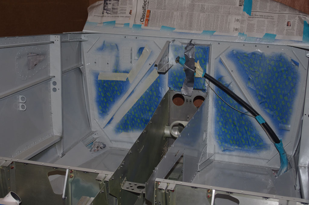
A rudimentary paint booth is constructed of large cardboard sheets and thin plywood paneling.  This is not intended for long term use, just enough to keep paint/fumes fairly contained on the side.


IMGP6678IMGP6687
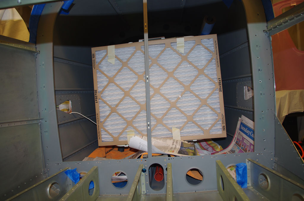
Fans/filters placed in the tail and on the plywood barrier are just enough to keep a gentle air flow from back to front, then out the shop door.  This concept, while looking very crude in the photos, worked extremely well in practice.


IMGP6681IMGP6686IMGP6690
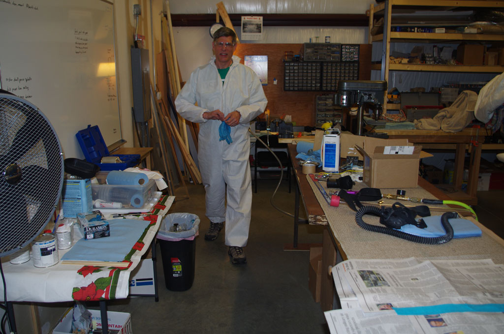
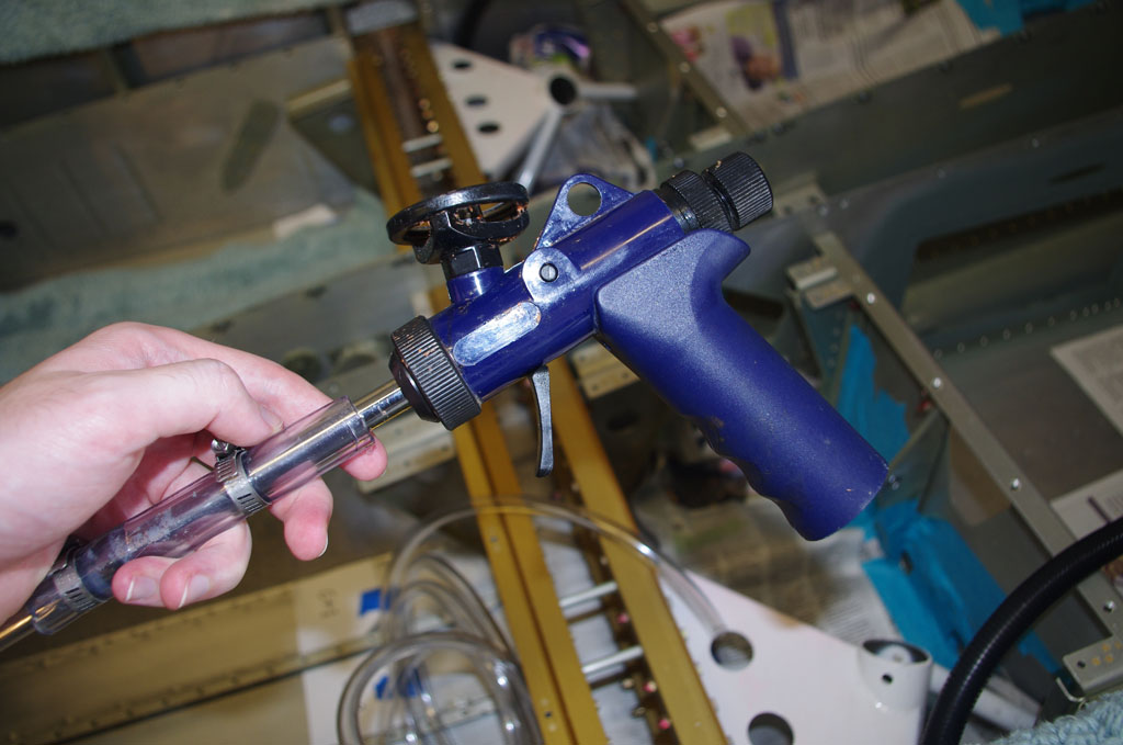
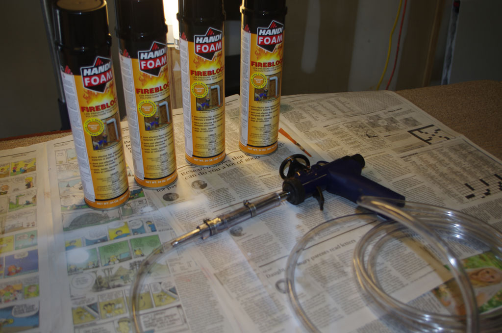
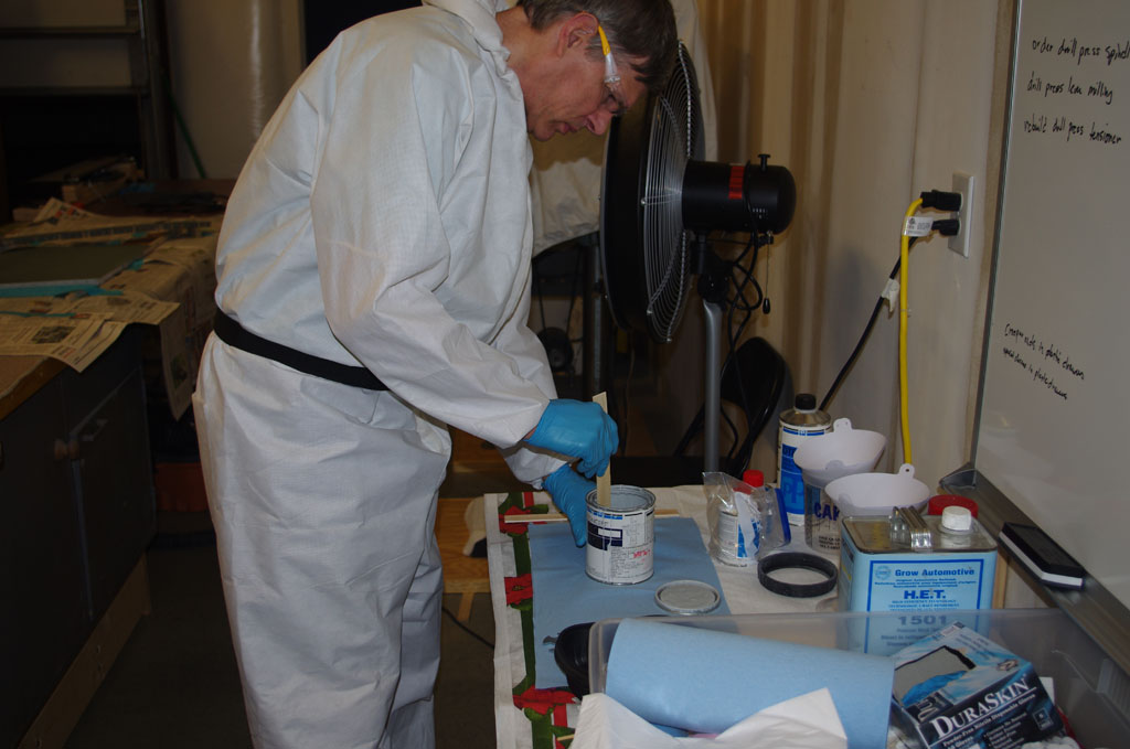
The basic process getting ready to shoot remains the same:  suit up, shake and mix well. Then pucker and pull the trigger.


IMGP6691IMGP6692
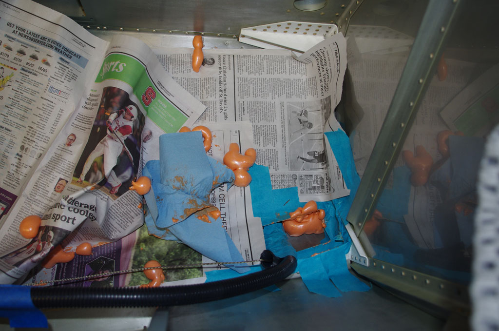
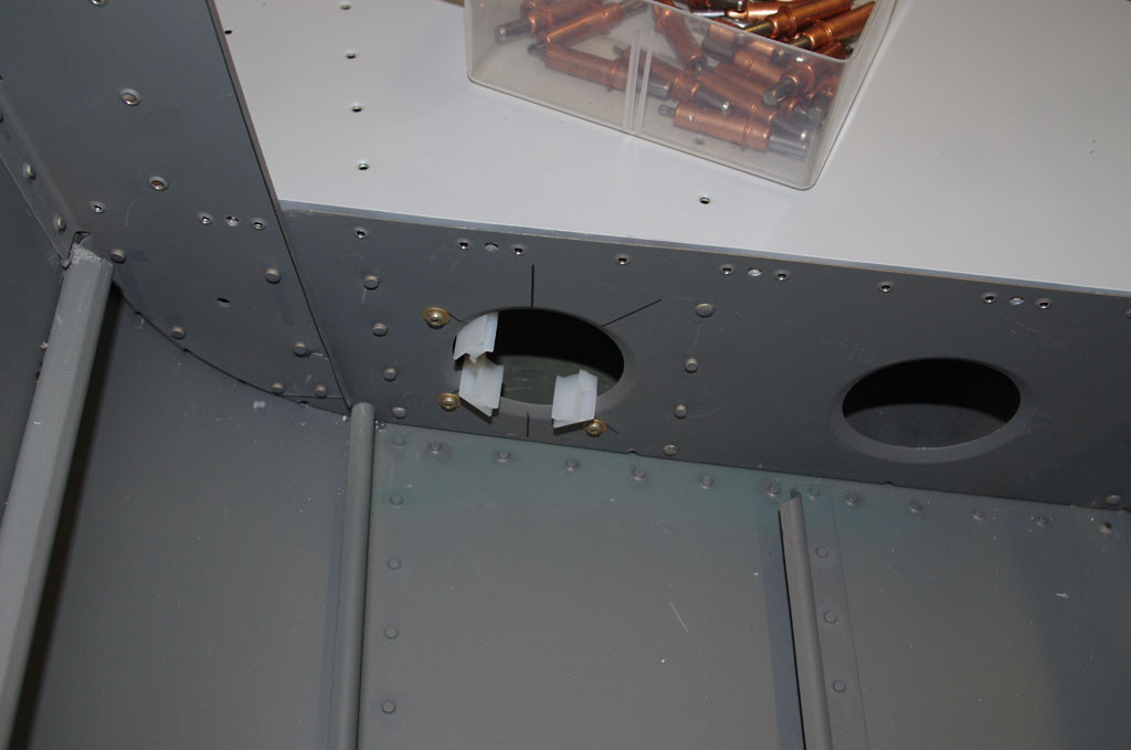
Now for the results – baggage door and rear seat areas. Only those visible areas are painted. The remaining parts are covered by side or floor panels.


IMGP6693IMGP6694
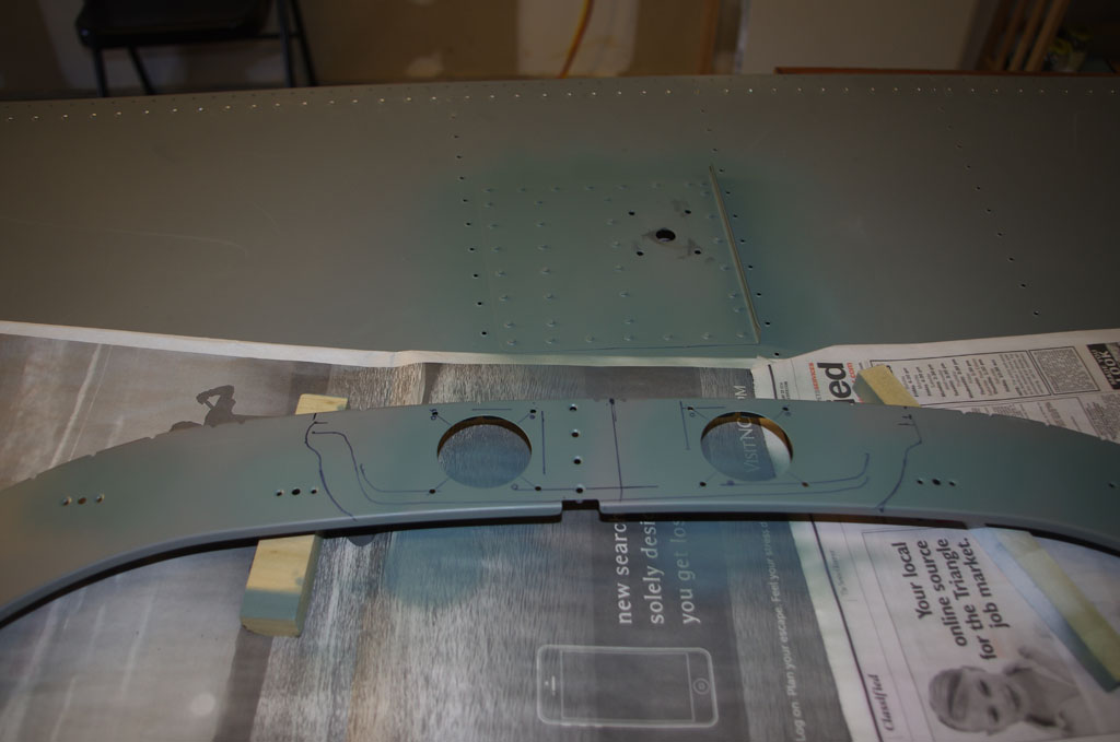
Firewall and side panels.  Some areas here are perhaps a bit thin on paint, but no worries about appearance, as these sections will be covered with soundproofing material and probably panels as well.


IMGP6695IMGP6696
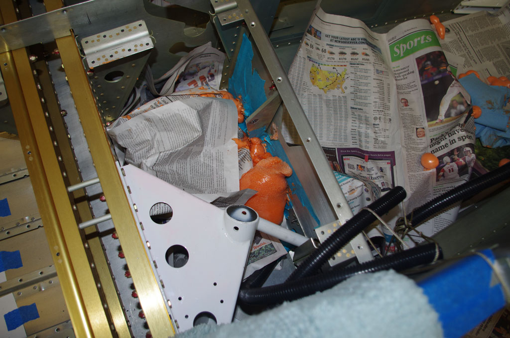
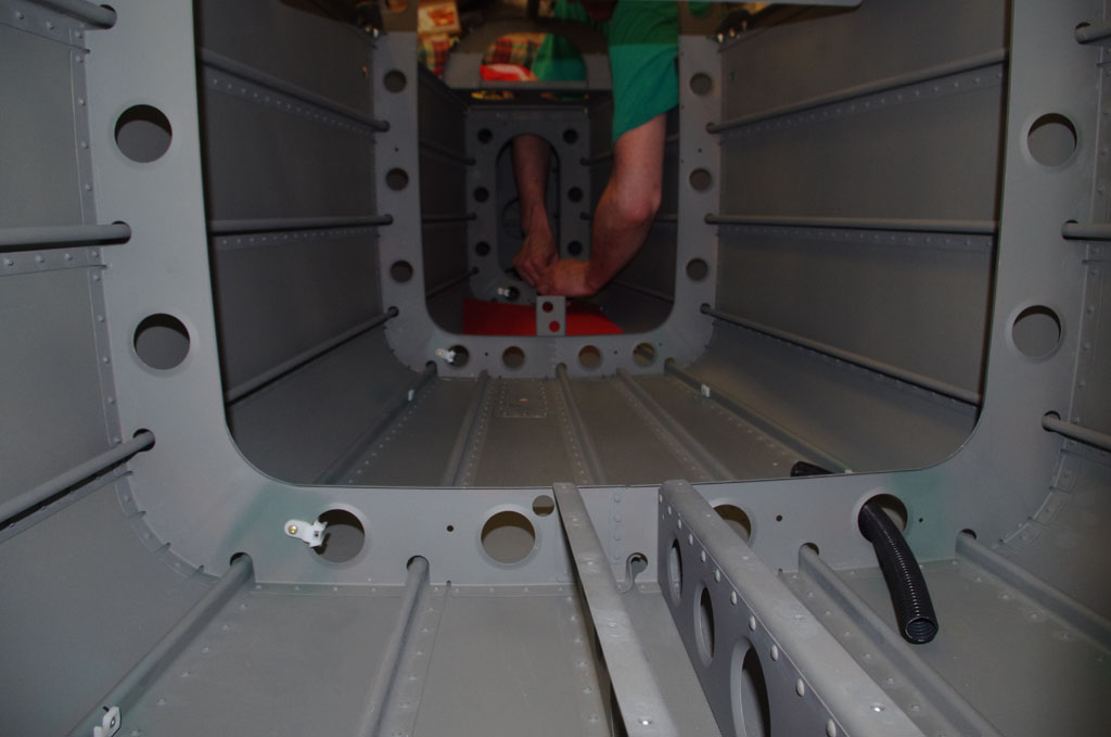
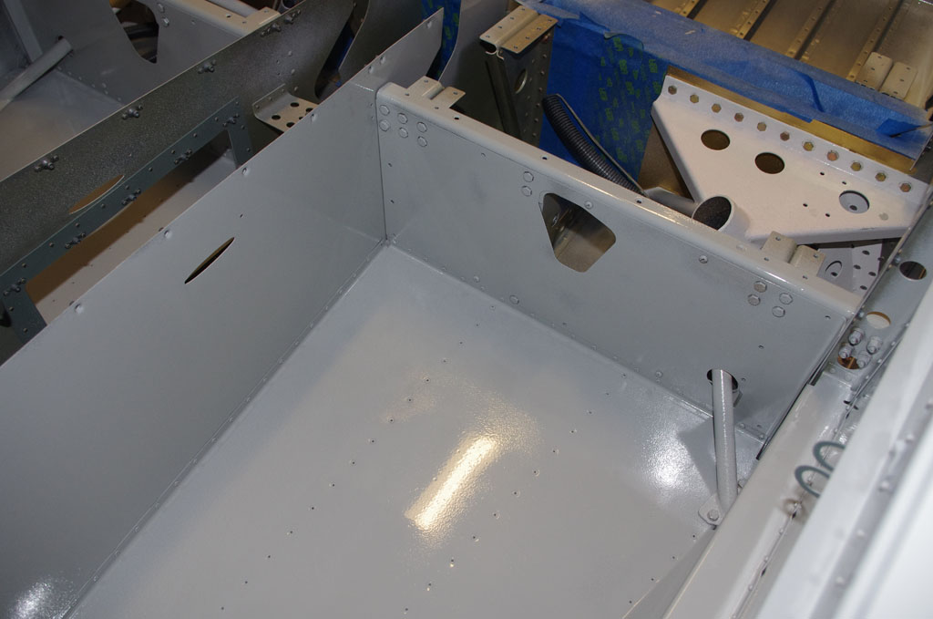
Front floorboards and forward seating areas.


I used PPG Concept paint coded DCC in Boeing grey (BAC707).  This is a three part system with paint, reducer and hardener. This stuff is fantastically hard, flows together when applied properly, and covers very well. Any runs can be sanded and resprayed for a smooth finish .  The downsides to this material are its high expense and caution must be taken for personal safety. The poly-isocyanates in the hardener are toxic and exposure must be avoided. Fortunately I have the HobbyAir breathing system, safety glasses, gloves and professional paints suits for protection.

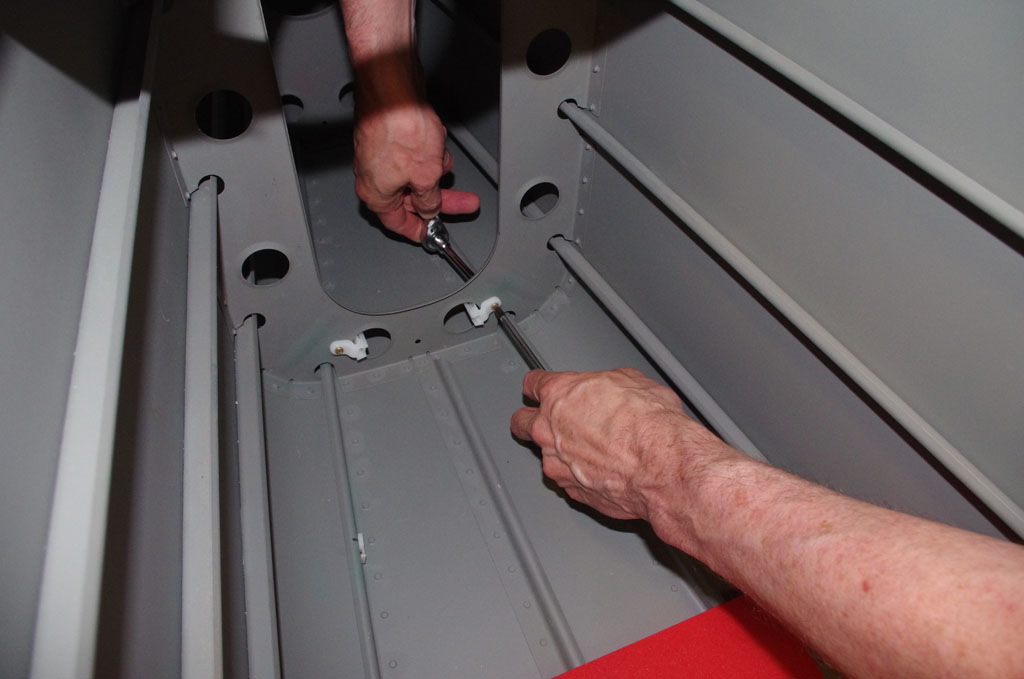
Next steps are install the sound dampening material, run the electrical conduit under floor boards, then rivet all the floor panels in place. I may not do another round of painting, as the overall results for the first round were pretty good.


COM2 Antenna Plate (2)

This week saw another set of clean-up activities – things started in the past, but finally with time to address.  Primary among these was final attachment of the COM2 antenna plate to the upper tailcone skin.

IMGP6649Step one is Pro-Seal around the major antenna holes and fasten tightly with clecoes.  After drying overnight, the excess sealing material was removed and dimples cleaned out ready for riveting.


IMGP6659I decided to back rivet all locations with a 4″x6″ plate obtained from Cleveland Tools for this purpose.  To avoid the previously committed sin of slipping off the plate during riveting, this time I line up the plate in a known position by marking the antenna holes with a black Sharpie.  By always keeping the holes aligned, I was assured plate would always be under the rivet with plenty of space on either side.


IMGP6664The outcome looks good. A bit of Scotchbrite preps the skin to accept priming.


IMGP6670The backside of the antenna plate and the newly deburred holes in the baggage bulkhead are primed with SEM self-etching primer to cover any bare spots.


Next up was attaching the two static ports (one left and one right) to the rear tailcone skins.  Wooden jigs were made to clamp the ports in  position while the Pro-Seal drys.  Some folks use rivets and/or the Pro-Seal, but my experience is the Pro-Seal should be strong enough to hold by itself.

IMGP6644IMGP6646Front and back photos of the static ports while the Pro-Seal drys.


The baggage door parts were primed and painted in earlier posts.  The outer frame and hinges were then riveted together for proper alignment.  With the inner and outer panels cloeced into place, the frame now has the appropriate configuration and rigidity to final fit the outer panel to the baggage door opening in the fuselage side skins.  A gap of about 1/8″ all around is desired to allow a tight fit, but enough room to close freely.

IMGP6666Here the outer edge of the bottom and right sides are marked with a Sharpie to final dimensions. The standard hand file and Scotchbrite process was used to complete the shaping.


IMGP6667The inside surface of the outer panel is also primed with SEM self-etch. Next up for this piece is final paint with the BAC707 used for the cockpit interior.


Finally, I had purchased a $20 grinder from Craigslist earlier in the year.  It ran okay, but heated up quickly when in use.  I decided to replace the 6202-2RS bearings with a higher precision ABEC 3+ variety. Why – this is definitely overkill.  Well it only cost $10 for two of them, and I was curious whether it would make any difference.  In addition, the whole topic of bearing selection was a new and interesting topic for me to research.

IMGP6654To replace the bearings, the outer housings are removed with a pulley puller, then the bearings.  This leaves the raw shaft and stator with fan attachment.  The flaking insulation of the stator was removed, then sprayed with electrical insulation varnish.  Here is the cleaned shaft prior to treatment.


IMGP6655The shaft was placed on two V-blocks received from Rich at the estate sale.  The shaft was rotated slowly during the spray treatment.


IMGP6656Time for some more overkill.  Since I already had the shaft out, I decided to measure with my new test indicator and stand obtained on eBay for $12.50!  Nice price and the setup worked great.


IMGP6658The indicator itself is supposed to read 0.0005″ increments.  The outer portion of the shafts vary about 0.002-0.003″, not bad, but when multiplied by the diameter of the grinding wheels, the runout is quite visible on the wheel surfaces.  The deviation on the shaft between the bearings is about 0.010″.  These numbers don’t mean much as no adjustments were made to the shaft bend.  However I am trying to use this information to gain some experience on tolerances.  The overall outcome is a smoother running and cooler motor.


I then used the test indicator on my drill press chuck – almost not detectable, which means the unextended chuck is <0.0005″.  Outstanding, but the proper test of drill press runout is fully extend the quill and measure at the end of a 4″ machinist dowel.  Since my Delta 17-900 drill press does not have a quill stop, this will be a two-man job to measure at a later date.


Sound Damping and More

This week saw a number of miscellaneous activities completed.  The main work involved spraying foam fire block material under the forward floor panels, mainly for sound damping purposes.  Other items included conduit tie-down locations and 2″ air vent hole punching.

IMGP6604IMGP6611I borrowed a specialized gun for Fomo products from my friend Tal.  An extension was fashioned with Tygon tubing to insert under the already fastened floor panels of the fuselage quickbuild kit.  The tubing is held in-place with two 5/8″ hose clamps.


IMGP6608IMGP6607This stuff expands rapidly and is very sticky.  I tried to cover large sections of the exterior surfaces for fear of getting this stuff all over.


IMGP6638IMGP6640Once out the the nozzle, the foam becomes unruly and difficult to place in the right areas.  Despite my best efforts to contain the stuff, it still wound up in undesired place.  Notice how much it grew right out of some holes.


IMGP6642IMGP6643After removing the tape and paper, the expanded foam coming out is visible in a few spaces.  The results from a sound perspective were very good.  Tapping on the floor panel results in only a dull thud – which should indicate the panel cavities are fully covered. Next up – final cleanup and get ready for interior paint!


Another action was finalize the conduit runs from the baggage area back to the tail section.  The right side run will be used for COM antenna and magnetometer, the left side for strobes.  The intention throughout the plane is use 0.100″ fiberglass cable lace instead of plastic tie wraps to secure conduits and wires.  This method is old school and requires more effort to install, but is much more flexible and should last forever.

IMGP6617This is the back of the baggage compartment where the black conduits run forward.


IMGP6619Looking backward from the baggage ares, the Panduit nylon stand-offs can be seen in the lightning holes on the right.  Also visible are the smaller nylon tie downs riveted to the stiffeners.


IMGP6623The final stand-off is being install in the rear bulkhead.


Finally, my technical counseller Terry Gardner has a #2 Diacro punch perfect for precision setting the two air supply holes needed in the baggage bulkhead.

IMGP6625IMGP6627The punch is setup and ready to roll…


IMGP6630IMGP6636Line it up, pucker, then pull the lever.  Within milli-seconds a perfect 1.9735″ hole  is positioned exactly in the bulkhead.


IMGP6637Not the best picture, but it does shows how well the punched hole and the 2″ SCAT tubing bracket align.  Just a bit of deburring the hole edges and then good-to-go.