Category Archives: Section 11, Empennage Attach

VS Attach and Misc.

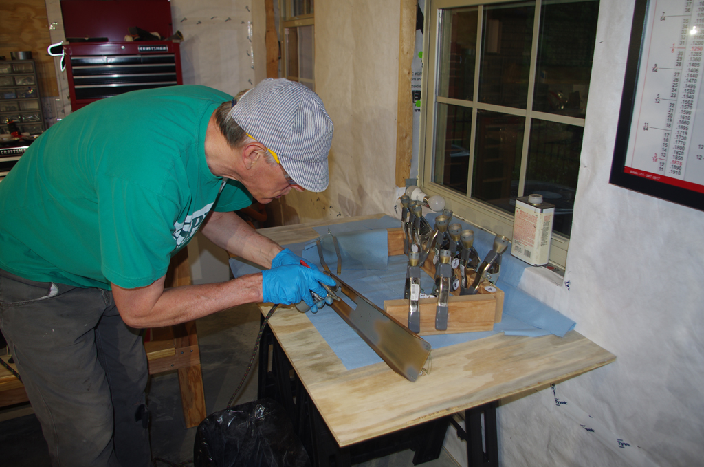
Much of the finalized assembly was not photographed in-progress, as fabrication of the parts was generally covered in previous posts.  Plus I really wanted to get done without taking further time on the website. A greater reliance on video content was made as the build headed for completion.

VERTICAL STABILIZER

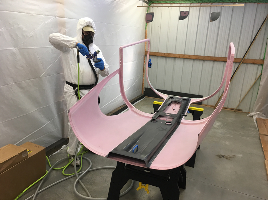
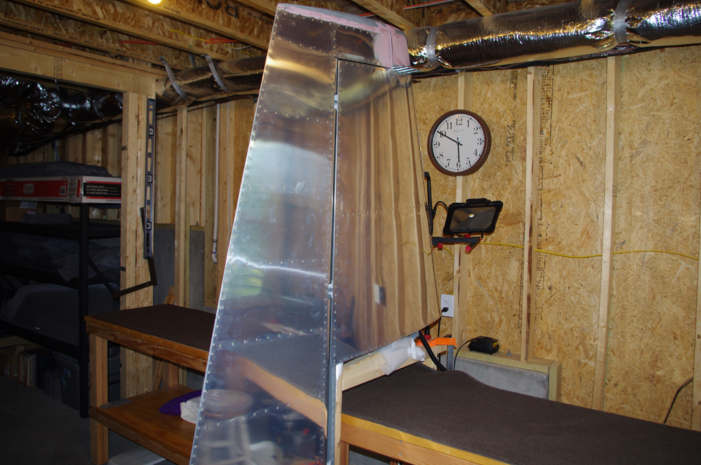
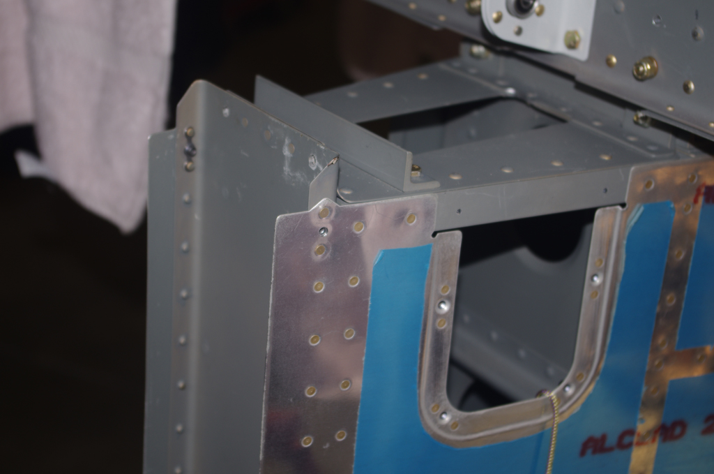
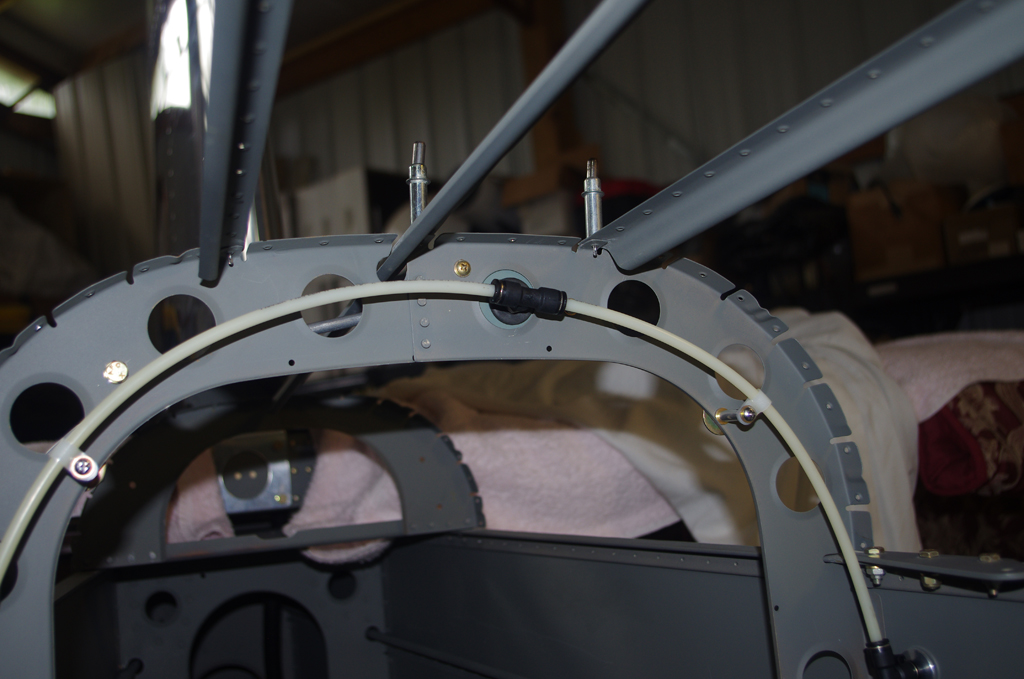
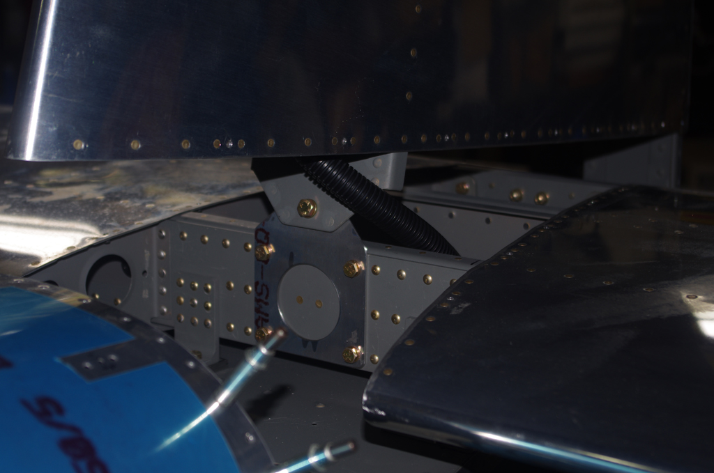
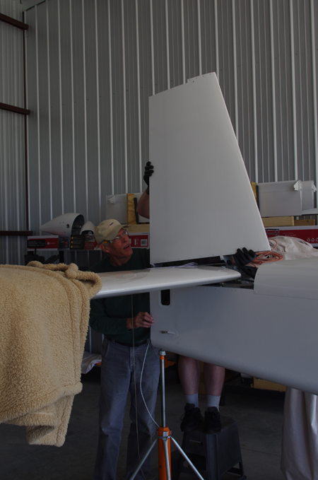
Here the vertical stabilizer was being attached to the empennage – hopefully for the last time.


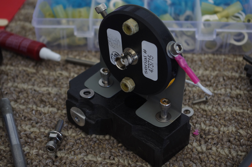
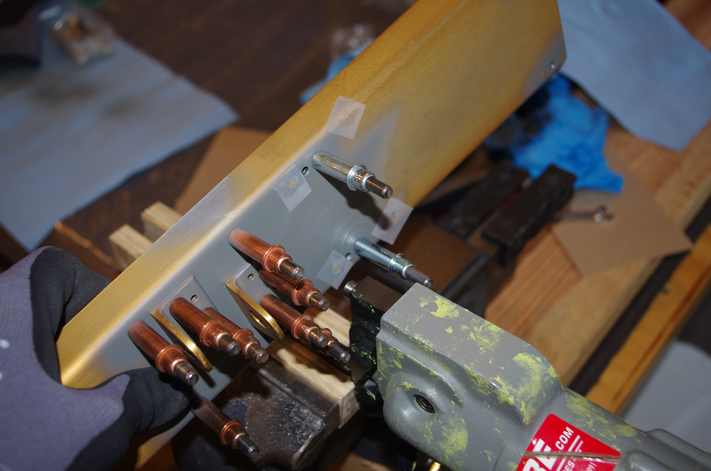
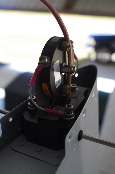
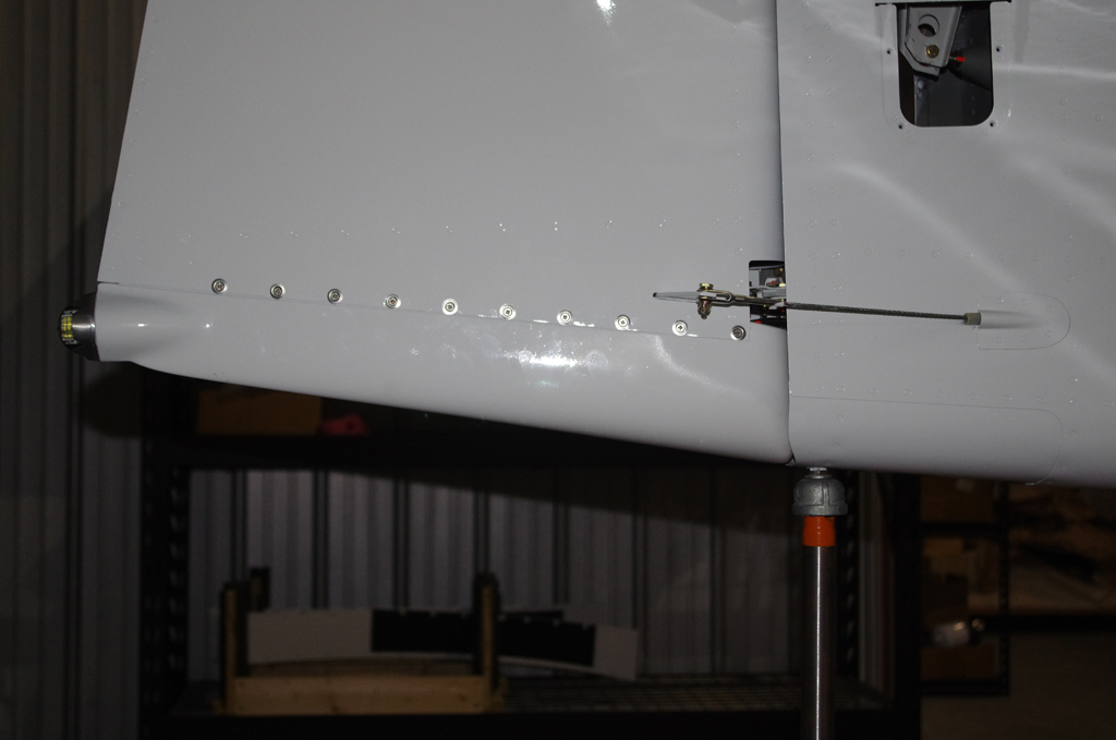
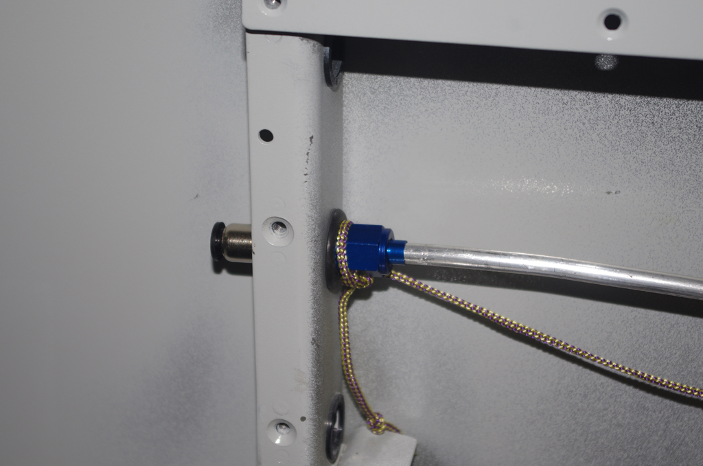
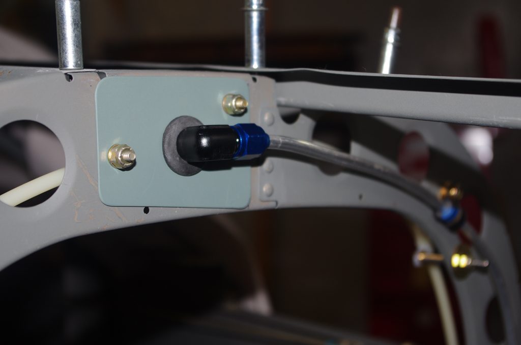
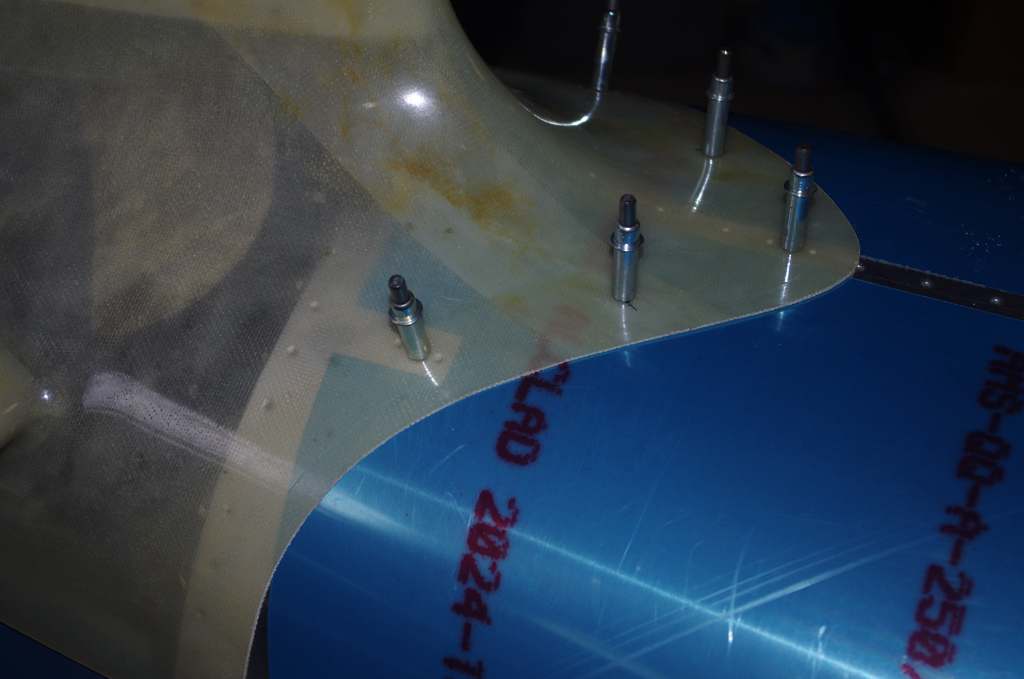
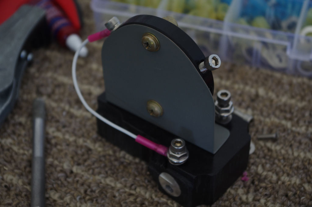
I made this custom NAV antenna bracket many moons ago. In retrospect, I would probably forgo this bracket and mount the antenna directly under the fuselage.


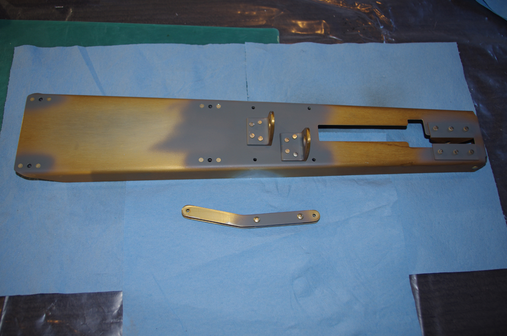
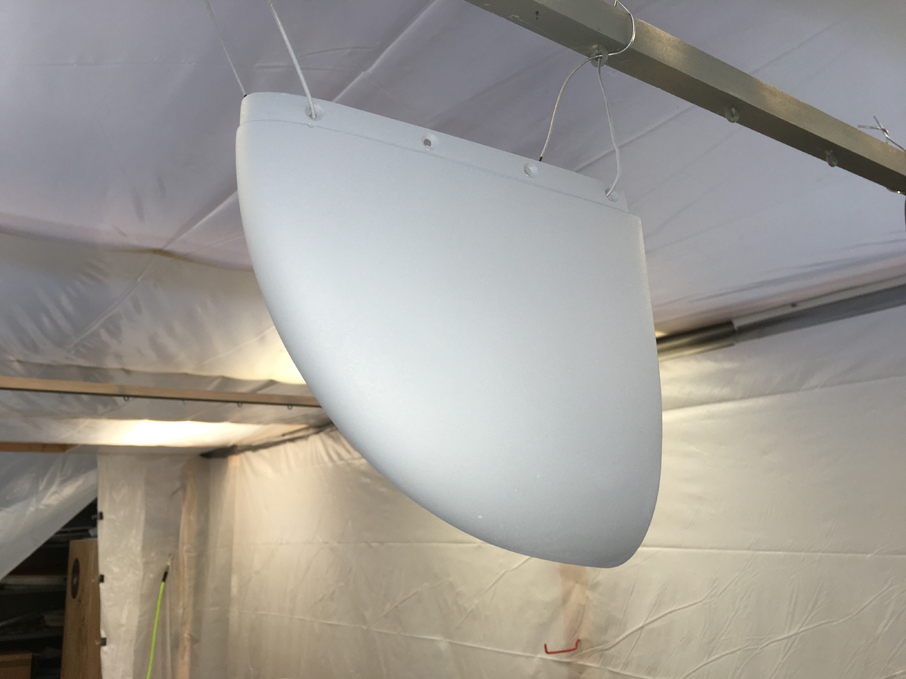
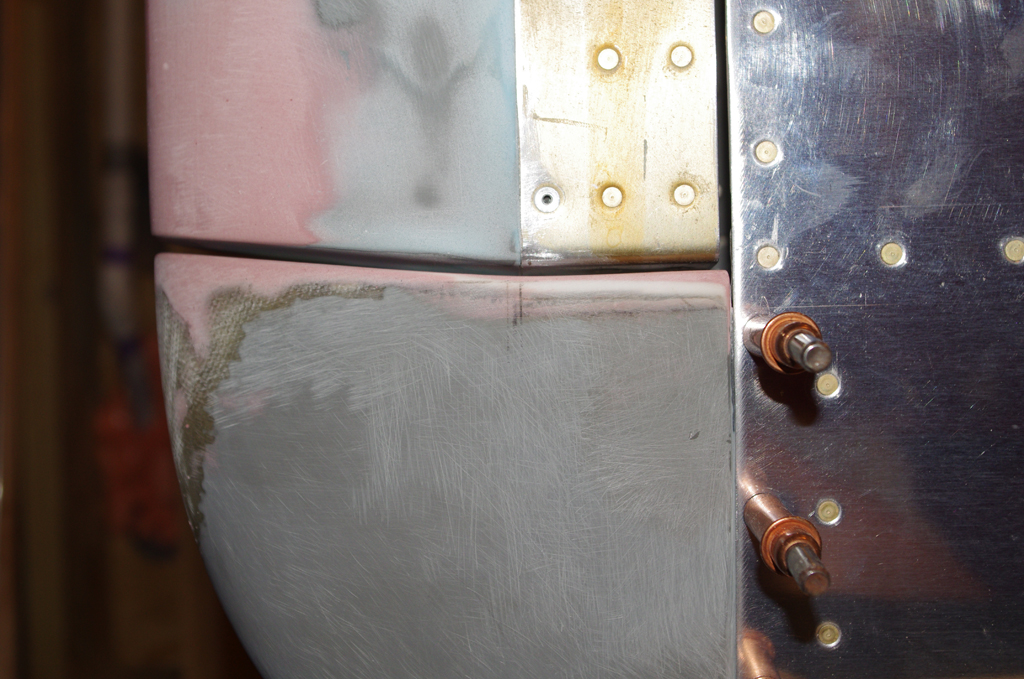
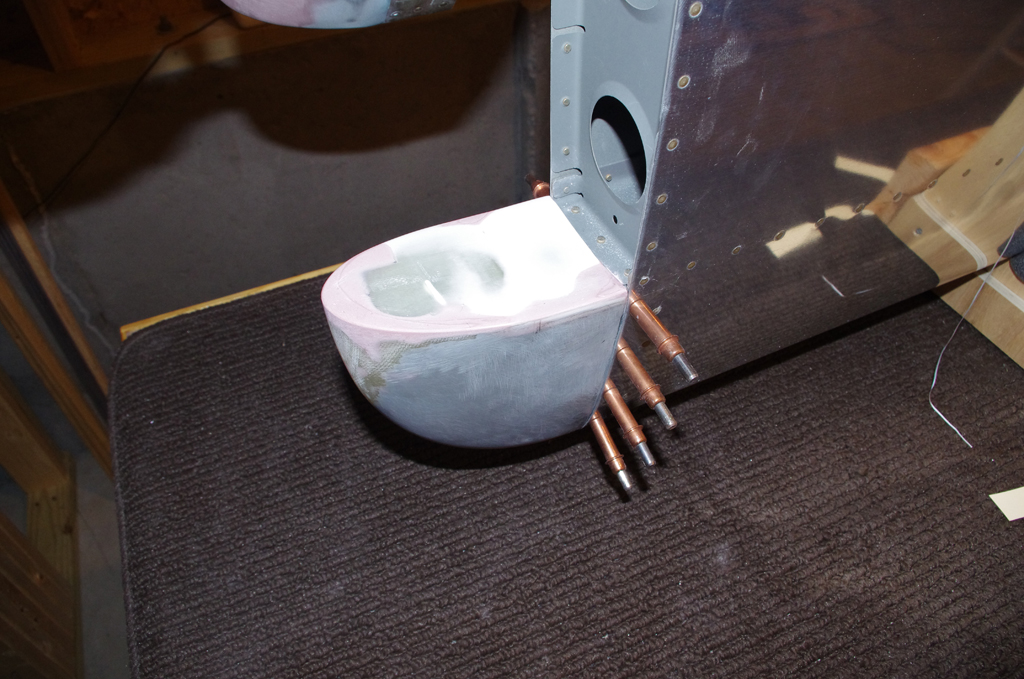
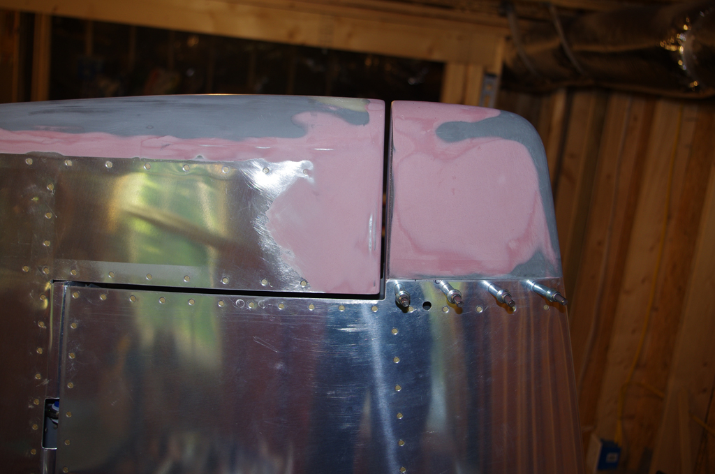
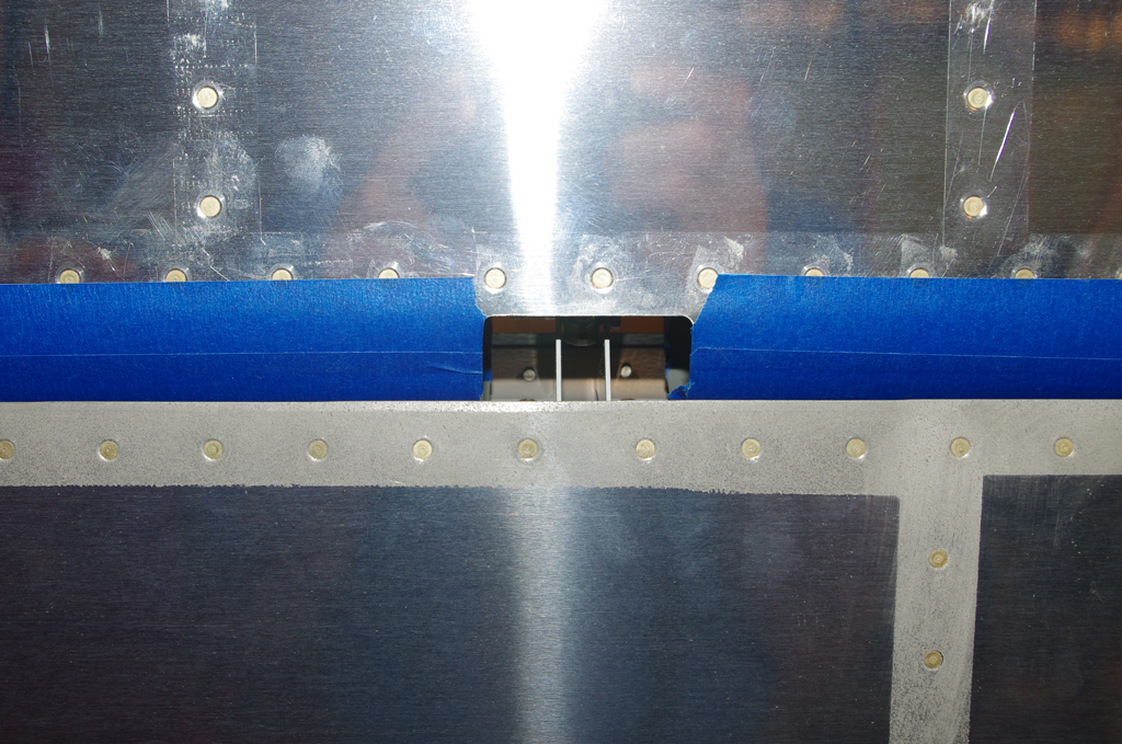
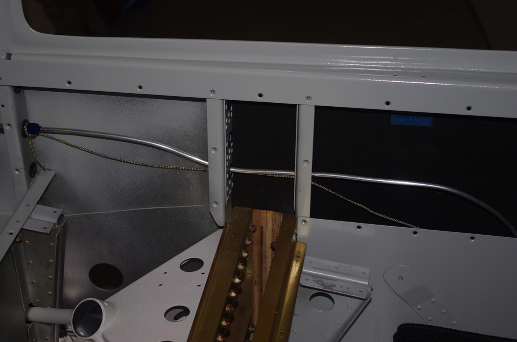
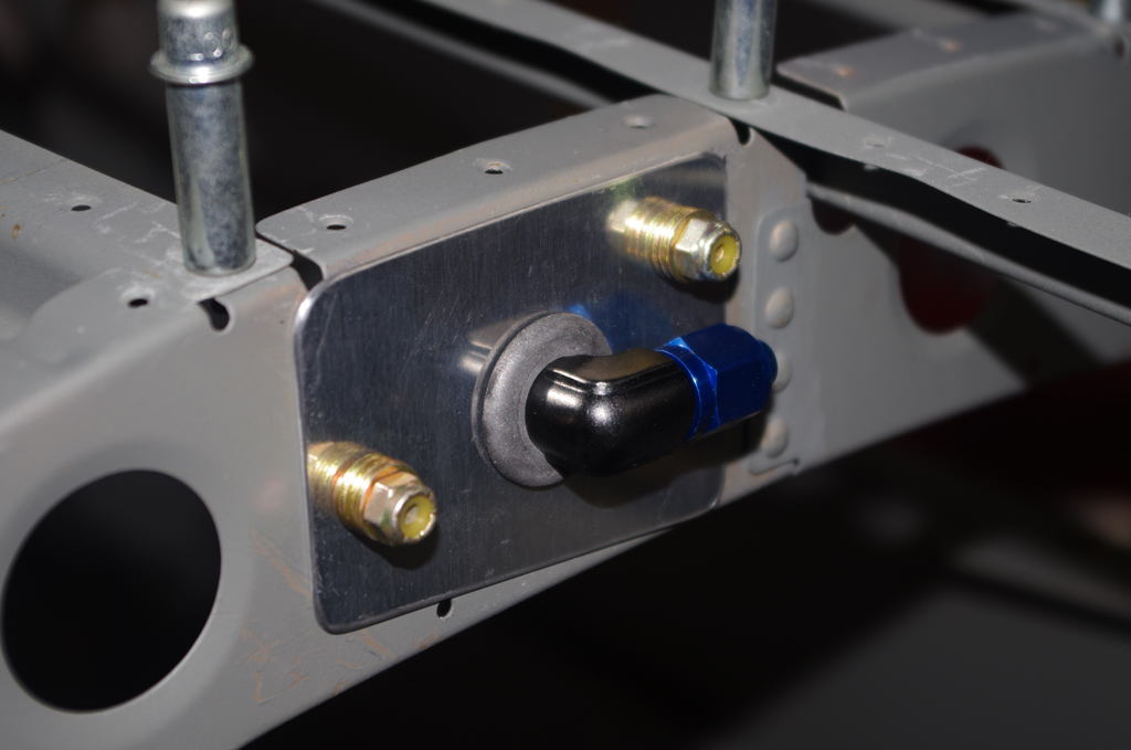
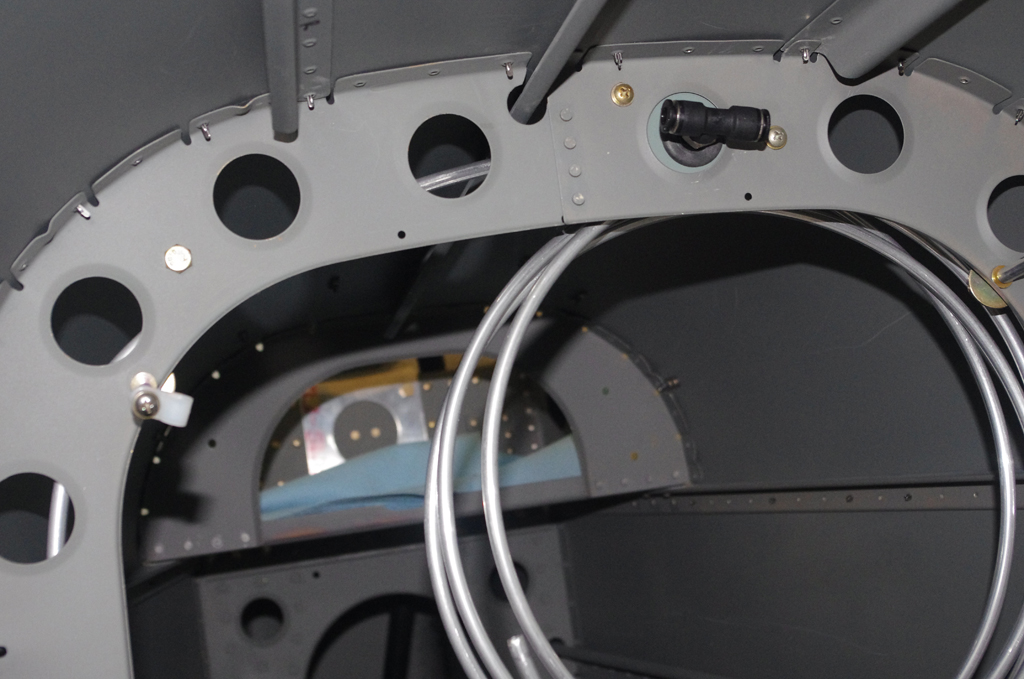
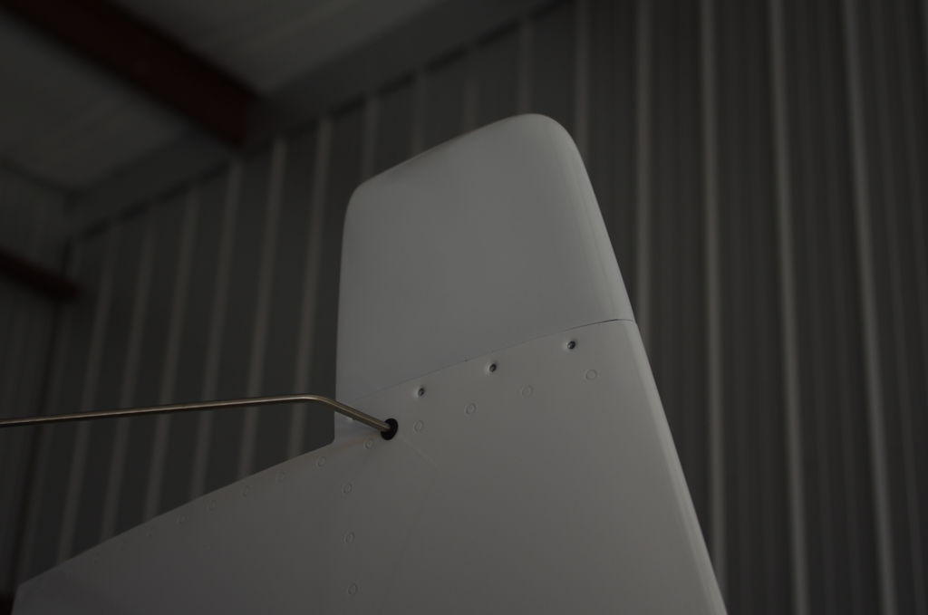
Anyway – here was the final connection and covering by the VS cap.


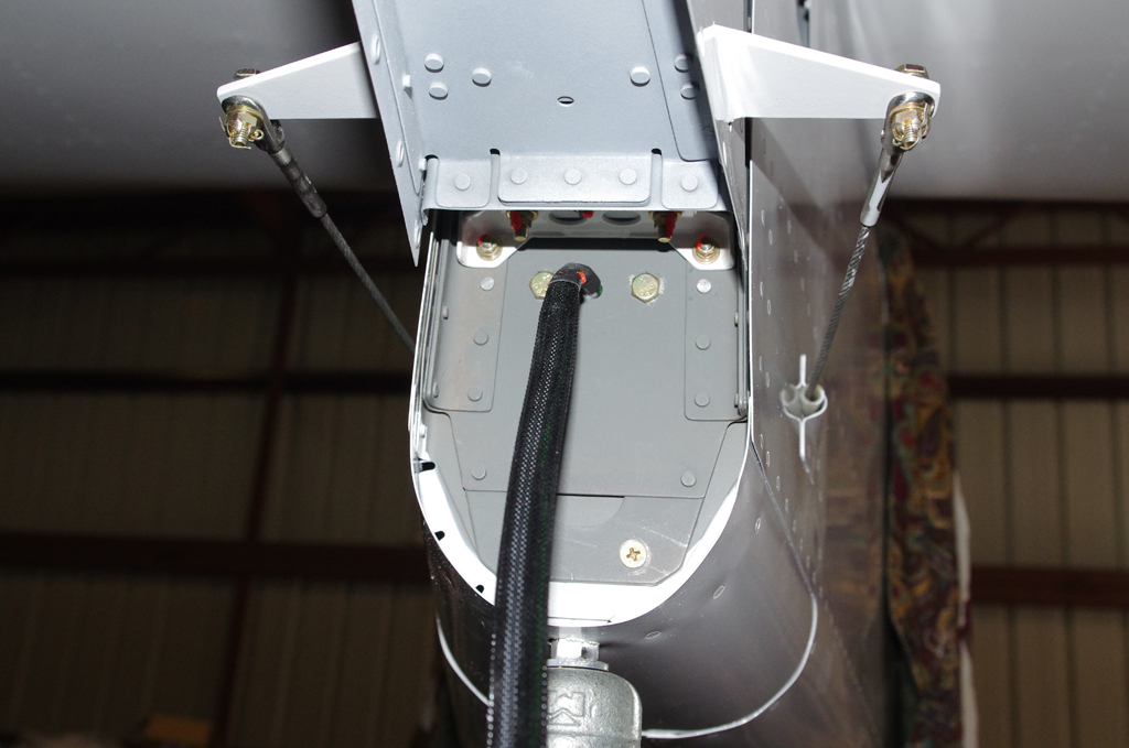
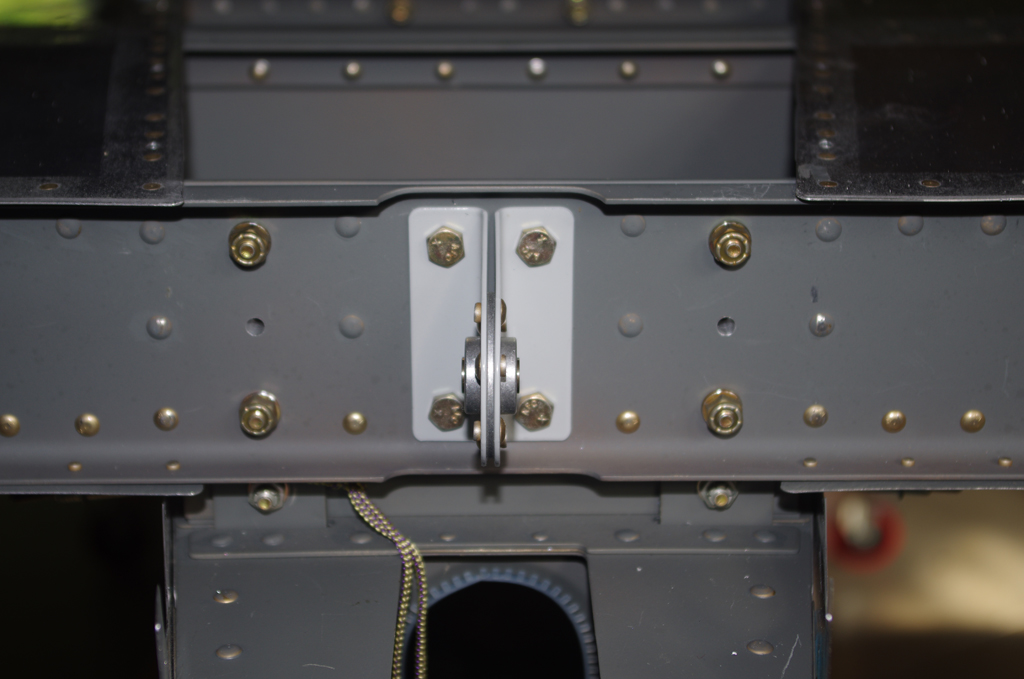
The left photo shows the Suntail Strobe/Nav wiring exit between the rear fuselage and the rudder bottom.  On the right is the original elevator stop replaced with a much heavier and larger alternate means to comply with Service Bulletin SB18-03-30 from Vans. This modification prevents over-rotation of UP elevator.


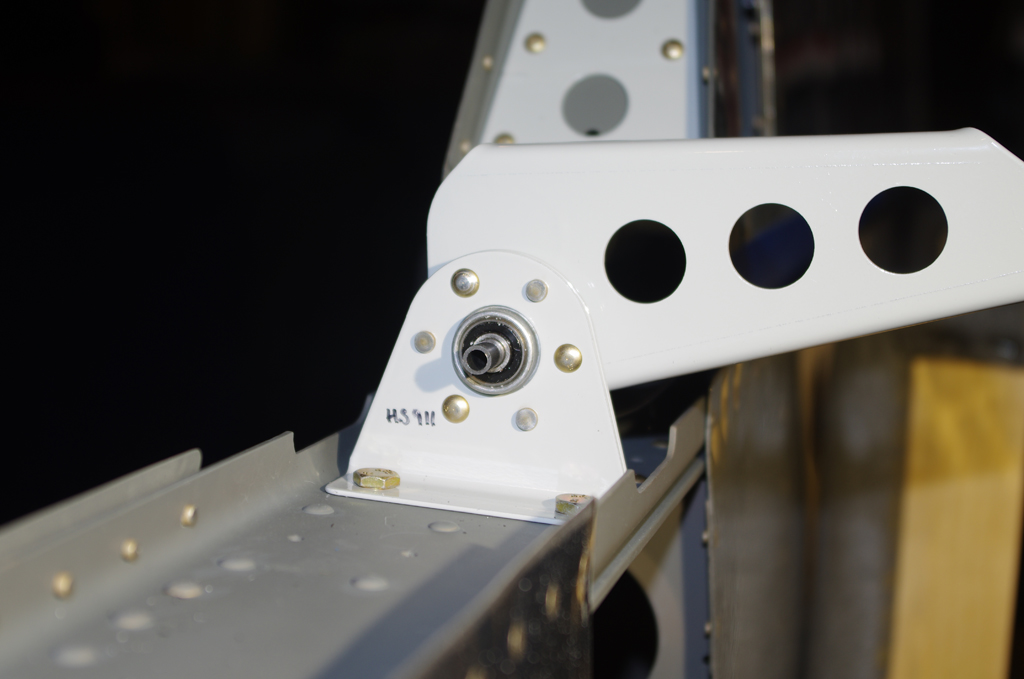
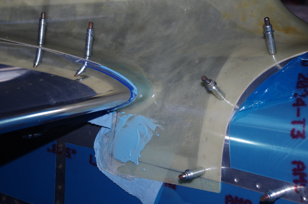
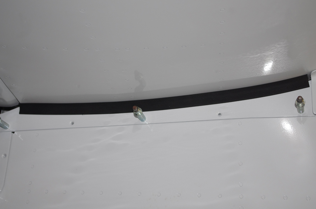
Following attachment of the rudder bottom, intersection fairings around the VS and HS were installed. Thin rubber edging protects the HS paint from the elevator trim covering. Note the elevator horn to elevator push rod assembly in the upper right of the first photo.


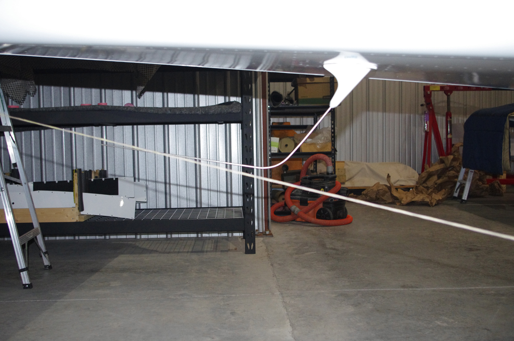
This photo shows a taut line extending from the main wheels at ground level to the rear tie down point.  This confirms the COM1 antenna will not scrape on the runway during takeoffs or landings.


BATTERY BOXES

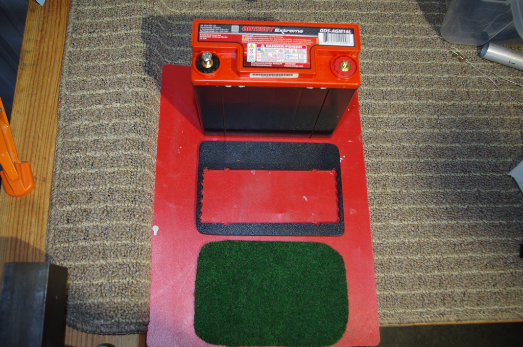
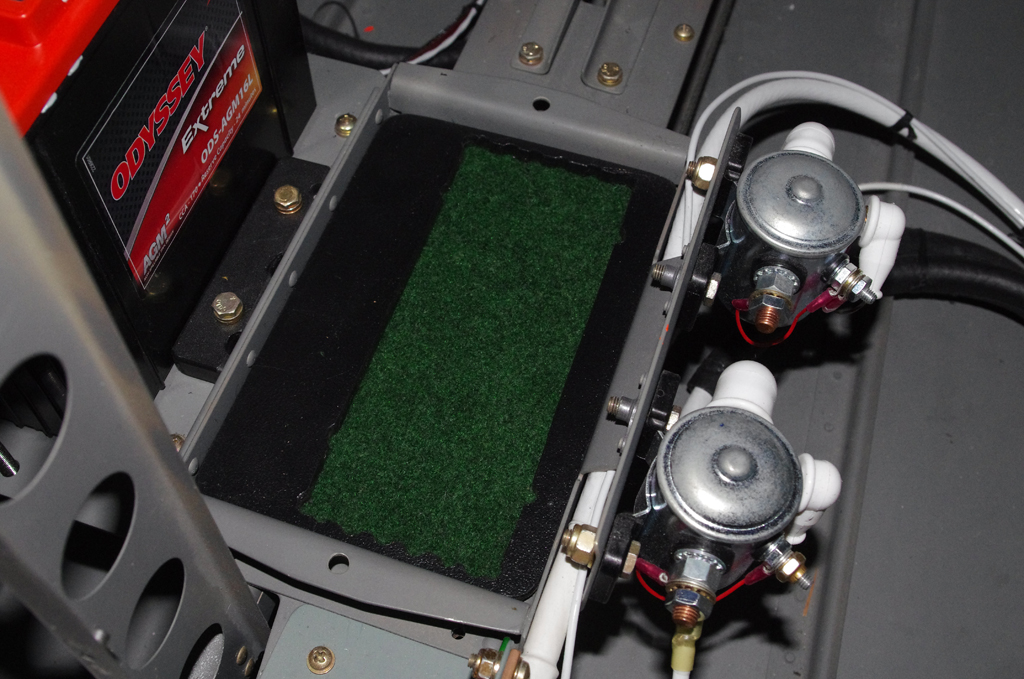
The Odessey 680 batteries were secured with a Delrin-like polymer frame with a felt underlayment for protection.  Here are the components before assembly.


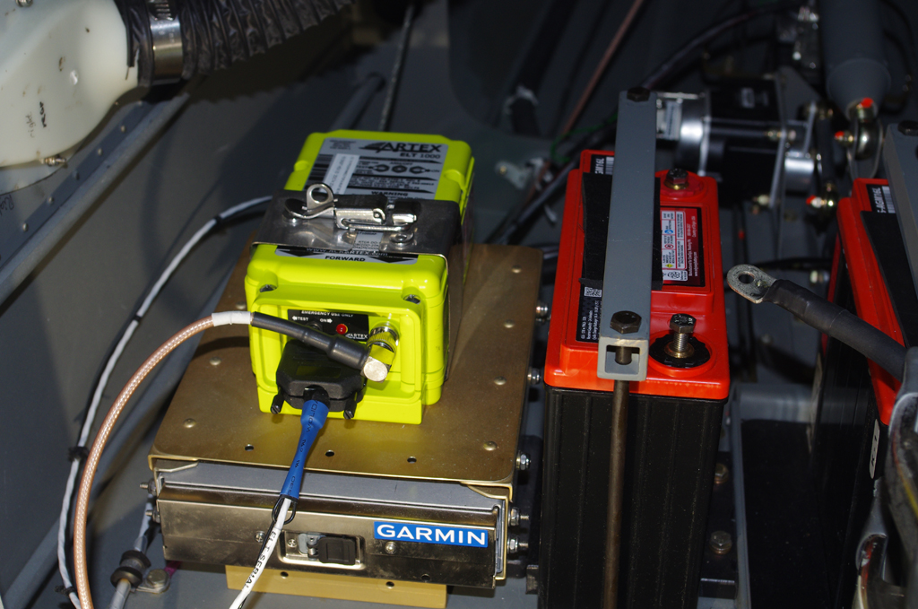
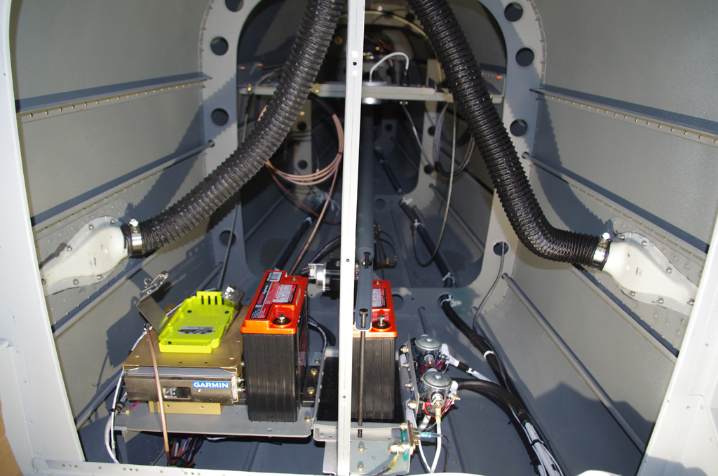
The final configurations of the battery boxes, Artex 1000 ELT, and the Garmin GTX45R transponder/ADSB behind the baggage bulkhead is show here.


Empennage Attach (6) and Custom Elements

The latest steps were in completing elements of the empennage attachment sequence. All the actions were of an interim nature, further posts on all elements will follow.

The last hole in the longeron at the rear of the vertical stabilizer required a nutplate install. The rudder had to be off to access the rivets.


Then install the rudder to test fit the cable linkages. The default lengths  in the plans of 1″ on for aft pedal and 2.25″ on the forward pedal did not align the rudder to neutral.  Further adjustments were required.


FLAP POSITION SENSOR

According to literature, many folks recommend using a Ray Allen POS-12 position sensor instead of the default AirWard configuration. A bracket was made earlier for the sensor, then a provisional lever mounted to a 2-piece collar clamp was used to test the throw length and hinge positions.


STATIC LINES

A custom bulkhead configuration of 3/4 rubber grommet, then a push-to-connect pneumatic fitting connected to NPT-AN4 adapter was made for the forward 1/4″ Verstube termination.


The static tube pulled through the cable runs was aluminum instead of plastic.  I wanted to ensure this would never require a replacement after the plane is finished.


A similar fitting configuration was used in the rear for a permanent attachment.  A custom mounting bracket uses the existing lighting hole as a pass-through. Standoffs will hold the plastic lines from the external static ports.


The aluminum tube was run up the bulkhead rear.  It is fastened with 1/4″ diameter Adel clamps and will be terminated at the push-to-connect tee.


The final configuration still needs to be tested with soapy water for minor leaks.  However, once tested, the ‘home run’ of aluminum tube through the mid-fuselage should never require additional maintenance (at least that is the intention).


EMPENNAGE FAIRING

Finally the gaps between the raw empennage fairing and the horizontal stabilizer were removed with SuperFil.

Empennage Attach (5) and Empennage Fairings (7)

Attachment of the horizontal stabilizer enabled the final configuration of the elevator control rods and elevator stops.

Match drilling the forward spar shims and aft bracket were performed to mount the horizontal stabilizer.  The UP position of 30 degrees exactly matches specification. The DOWN angle, even after considerable filing of the stop bracket, was finalized about a degree shy of the expected 25 degrees.


These pictures show the vertical stabilizer forward and aft attachments after the elevators were removed. Two mounting shims under each forward HS spar attach pad were also match drilled and bolted on before VS install.


The empennage gap cover under the HS was clecoed into place. The rear section overlaps the inspection port cover.  Both are match drilled together through the longeron.


The plans call for only three screws per side to hold the forward section of the empennage fairing.  Many pilots have suggested additional fasteners to prevent fiberglass bulging due to air stream pressure over the fuselage. Here intermediate points were drilled midway between the default points. Nutplates for #6 screws will later be added to the upper aft skin.


Front and rear photos of the match drill screw points on the empennage fairing. The aft points require special care when trimming to not interfere with either the elevator horn or the rudder motions.


With the main empennage components staged in place, the whole fuselage begins to look like an airplane.


OCTOBER 2020 UPDATE

Further trimming and edge preparation has been completed on the fiberglass empennage prior to priming.

Edges were measured against a scribe line formed into the part. Enough ‘meat’ needed to remain for the attachment screws to have sufficient structure to hold properly.


Because of the extra holes added, smooth curves based on circular patterns were applied.  Since fiberglass always seems to have numerous pinholes from the manufacturing process, a coat of Smooth Prime helps with initial underlayment.


MISCELLANEOUS

The forward and aft NACA air vents were fastened with ProSeal and #4 stainless screws into position.  Later SuperFil will be applied to smooth out the backing plate rivets.

Empennage Attach (5)

Upon return from AirVenture 2018, I began assembling parts for the trim mount bracket.  These parts were alodined in an earlier batch, but needed to be primed before riveting.

The pushrod ends and small parts for the trim mount bracket were primed using PPG DP40LF with an old airbrush I had acquired almost 40 years ago.  The amount of paint applied is very easy to control and the very low volume in the paint bottle was perfect for this small batch. The idea is prime just those parts touching one another with the airbrush, rivet, then prime the larger external surfaces of the whole assembly with the regular spray gun.


The trim mount parts were clecoed together prior to rivet assembly.  A pneumatic squeezer with a longeron yoke was needed due to geometry requirements to reach the Trim Cable Anchor Brackets.


Here are the riveted Trim Mount Bracket Assembly and the Trim Servo Links. The next actions were to continue work on the secondary battery mounting platform, battery contactor mount brackets, and the ELT device mount.


Empennage Attach (4)

The plans call for numerous parts requiring custom lengths or special fabrication.  I decided to process all the remaining control and push rods together.  This should reduce the alodine batches required, plus get some minor shop efficiency by not changing tools for every single piece.

Here are some follow-up pictures from the last post about how the larger diameter (>1″) aluminum tubes are measured and drilled.


The smaller flap actuator rods (1/2″ diameter) made of steel are much more difficult to handle, as the tolerance and angles are tighter.  Here a dremel tool with small grinder wheel is used to open up the end large enough to accept the screwed fitting.


Next comes the measure and alignment of the holes.  For these rods, two through holes perpendicular to one another and offset back 1/2 and 3/4 from the edge are required.  Unfortunately, the drilling on one rod end was not correct the first time. This resulted in a hole not aligned properly through the center of the rod.  It was bad enough I will have to make these over again.  Stay tuned for an update.

Empennage Attach (3)

Fabrication of elevator trim components and push rods was the order for this week. The trim motor housing was completed to the point of final riveting.  At this point the alodine/prime sequence will be used to treat the parts before assembly.

The distance between the attach brackets for the trim bellcrank must be measured carefully to ensure parallelism for the faces, properly aligning the pivot bolt with the trim motor.  Here an analog caliper is used to check the distance from the front edge to the back edge.  After a number of adjustments, I was able to get the faces within .005″ of parallel.


The elevator pushrod is made from a 73″ piece of AT6-035 x 1.5″ aluminum tubing and an appropriately sized threaded insert.  Here the circumference of the tube is measured for accurately drilling six evenly spaced #30 holes. After alodine/prime these parts will be connected with long shanked pop rivets.


A spring-loaded center punch is used to mark the six rivet holes 1/4″ from the edge of the tube.  After processing on the drill press, the clecoed parts are checked for correct alignment.


Also during the week I finished the end cap for the rudder bottom.  Looks nice.

Empennage Attach (2)

Use of paint booth and fabricate custom parts for empennage attach.

Over the last few months, Tal and I have been constructing a paint booth in his workshop.  This was our first run of priming parts in the just finished facility. Here he prepares to apply PPG DP40LF primer to the internal side of his canopy/overhead console, plus my horizontal and vertical stabilizer fiberglass tips.


My tips had to be sanded heavily to get the properly rounded outside profiles to match the elevator tips.  My experience is the fiberglass parts from Van’s are just rough approximations – to get this right requires plenty  of work.  Witness the sanding completely through the gel coat on the left part, this required additional fiberglass/resin layers on the inside to prevent holes.


Next up is prepare and fabricate additional parts on the empennage attach sequence.  The left photo shows a supplimental cover on the rudder bottom.  Not necessary, but it should help deflect some water from entering.  The right photos shows HS attach shims being made.


Attach points for the elevator trim motor and cables are being prepared on the left.  A 3/8″ spotting drill in a clamped vice ensures the attach rivet and bolt holes for the AN6 pivot bolts are correctly aligned to hold the trim bellcrank.


Empennage Attach (1)

While the horizontal stabilizer is in the jig for work on the fairings, there are also elements of control surface configuration which can be performed.  Checks on elevator up +30 degrees and down -25 degrees confirmed proper range of motion.  Then both sides are set to the “trail” position for drilling the elevator center bearing and elevator push rod bolt holes. To accomplish these tasks two drill guides were fabricated.

The first drill guide protects the center bearing while the pivot points in the elevator horns are configured.  The outer diameter of the guide needs to be reduced just small enough for a snug fit in the inner bearing.  The Delta drill press and Pferd files did the trick.  Once again I am amazed and happy at the incredibly small runout on the drill press!


The left photo shows the drill guide inserted into the center bearing for drilling the right elevator horn.  Next comes the actual drilling operation.  The right elevator is then removed and the same process used on the left elevator. The guide aligned everything perfectly and an AN4 bolt fits cleanly between both elevator horns.


To facilitate proper alignment of the push rod holes, a drill guide is made from a piece of oak sanded to the exact thickness spanning between the elevator horns. Caliper readings were used for initial hand sanding.  Then the piece is aligned and drilled perpendicular to the surfaces with the drill press.


Here the oak drill guide is clamped into place prior to drilling the second hole.  A piece of 3/16″ stainless rod is inserted to align the first hole for the right elevator with the undrilled face of the left elevator.  After drilling is completed, an AN3 bolt passes cleaning through both horns with perfect alignment.


This week was also some final sanding and fitting of the HS tips. The desired 1/8″ gap between the tips and the elevator fairings look good.


Empennage Fairings (5)

Work on the vertical stabilizer and rudder fairings was recently completed – at least for the time being and until final preparations for paint are underway.

My overall satisfaction level is good with the overall fit, gaps and blending of skins to fairings.


The upper and lower elements are clecoed in position to check the final rudder angles, gap tolerance on the upper rudder swing and rudder/vs skin clearance.  All within tolerance and acceptable for now.


The next fairings to be addressed are on the horizontal stabilizer.  To properly fit these, Section 11 Tailcone Attach elements must first be completed.  The elevators are fastened to the rod end bearings of the HS, then angles and clearances checked for free movement.

adfa


Here the HS cradles in the jig built many moons ago with the original construction.  The elevators are in position to begin work on the fairing alignment.


Close-ups of the gap between elevator tips and horizontal stabilizer, then the rod end bearding and the hinges.


Initial fiberglass filling of the HS end caps after rough trimming to shape with the elevator tips.  These are not straight – bending backwards at an 8degree angle. This is enough to  prevent the fiberglass molding from being simple.