Monthly Archives: February 2016

You are browsing the site archives by month.

Rear Wire Runs (2)

This week focused on finishing the wire runs under the rear seat panel and finalizing the left inspection ports for the antenna/steps.

IMGP6377
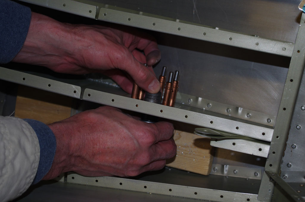
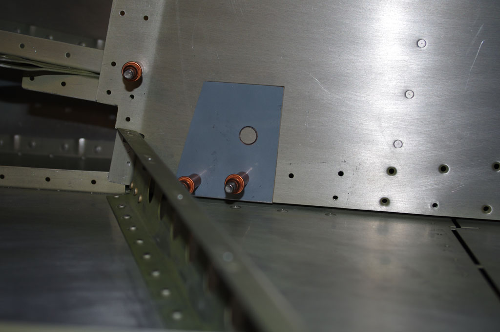
The edges of the rear seat panel are normally hidden behind a removable side cover.  This seemed like an excellent location for plunging conduit runs under the seat panel (which will eventually be permanently attached with pop rivets).


IMGP6379
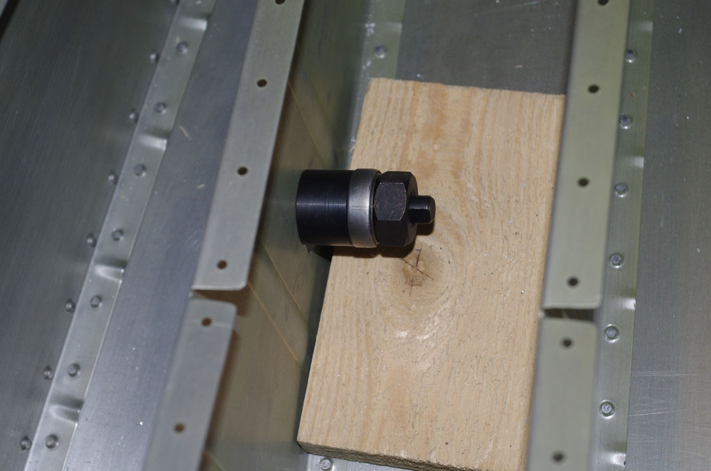
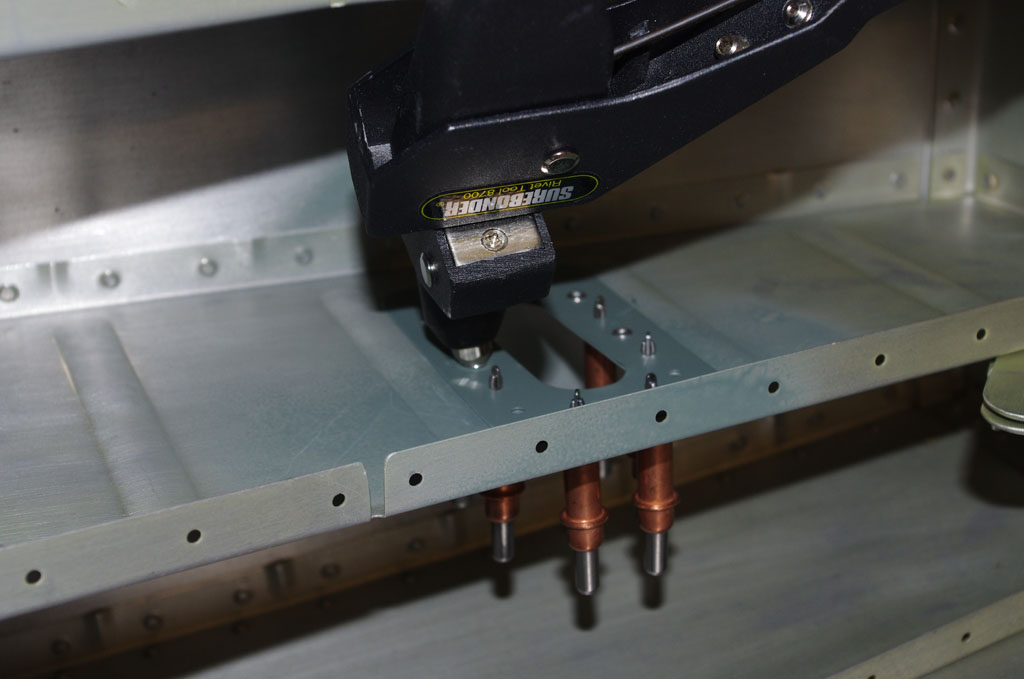
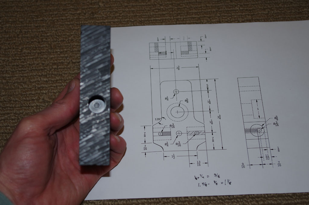
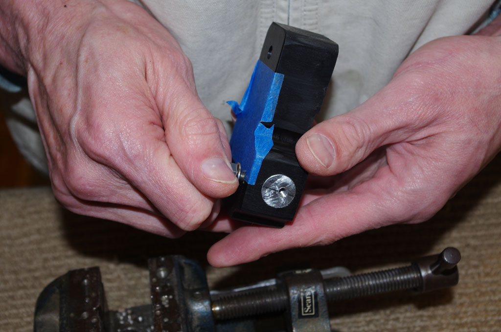
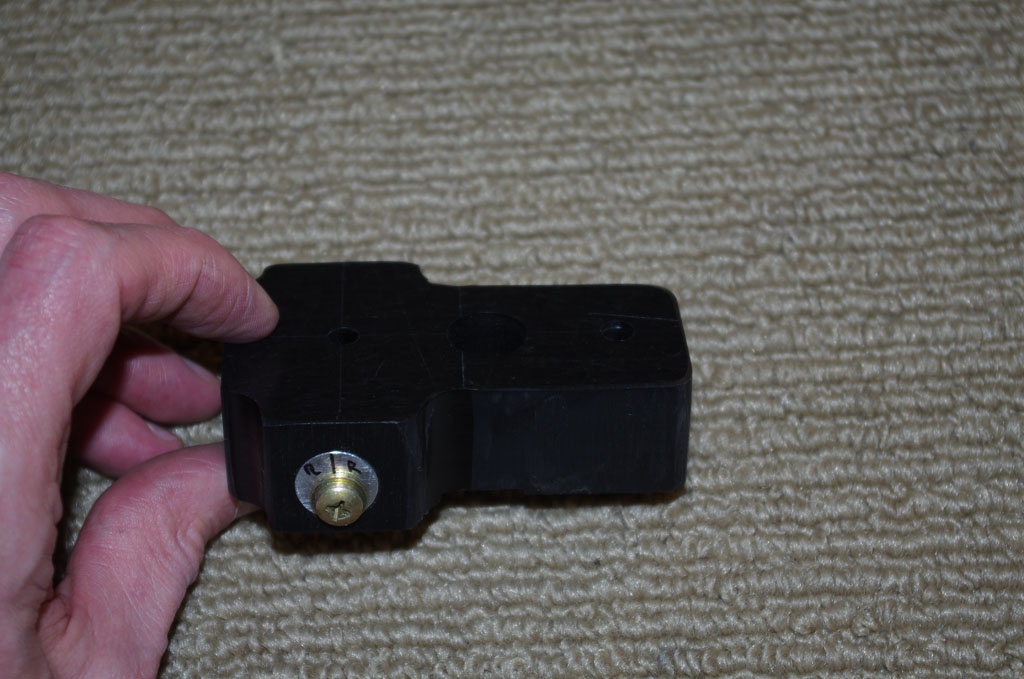
As with all additional hole in the plane, a reinforcement plate was fabricated the help hold the 5/8″ black corrugated conduit.  Here shows the plate clecoed in position.


IMGP6382
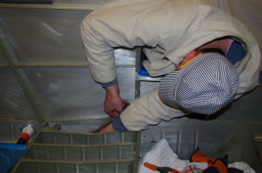
This next series shows a repeat of the inspection port fabrication, this time on the left side near the baggage door opening.


IMGP6384IMGP6389
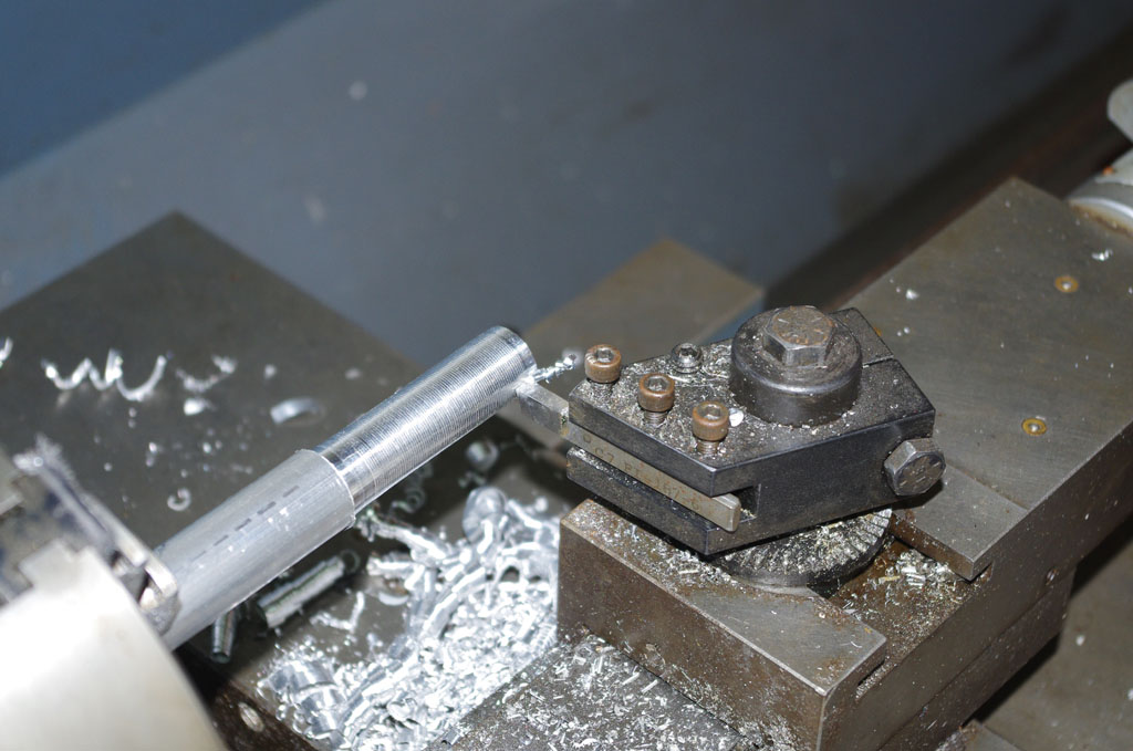
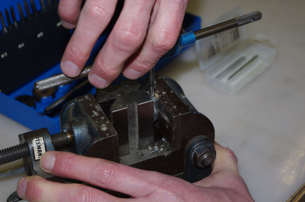
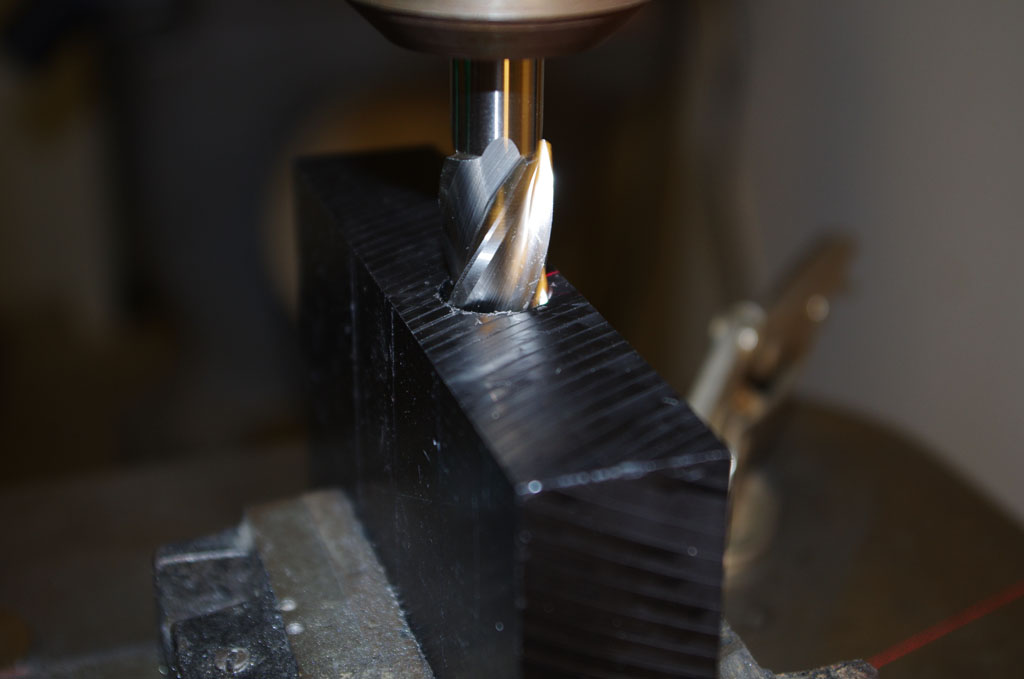
Layout the backer described in previous posts. Drill some pilot holes, then nibble a rough opening followed by hand filing and scotchbrite smoothing.


IMGP6390IMGP6391
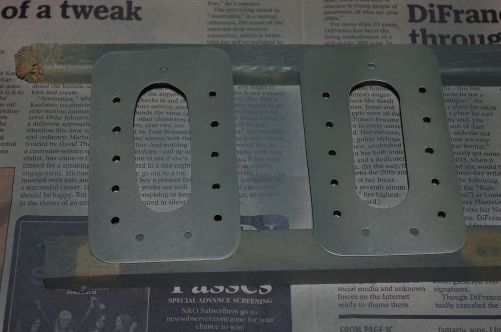
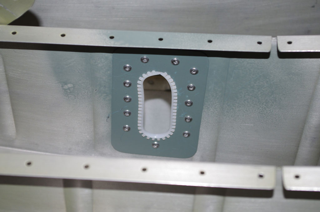
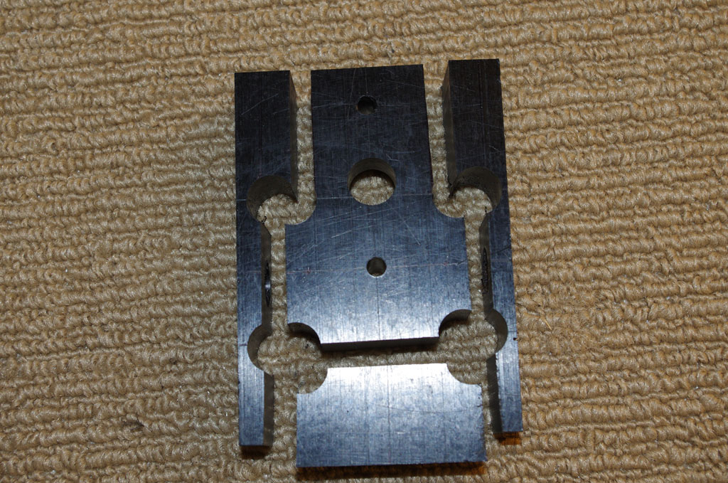
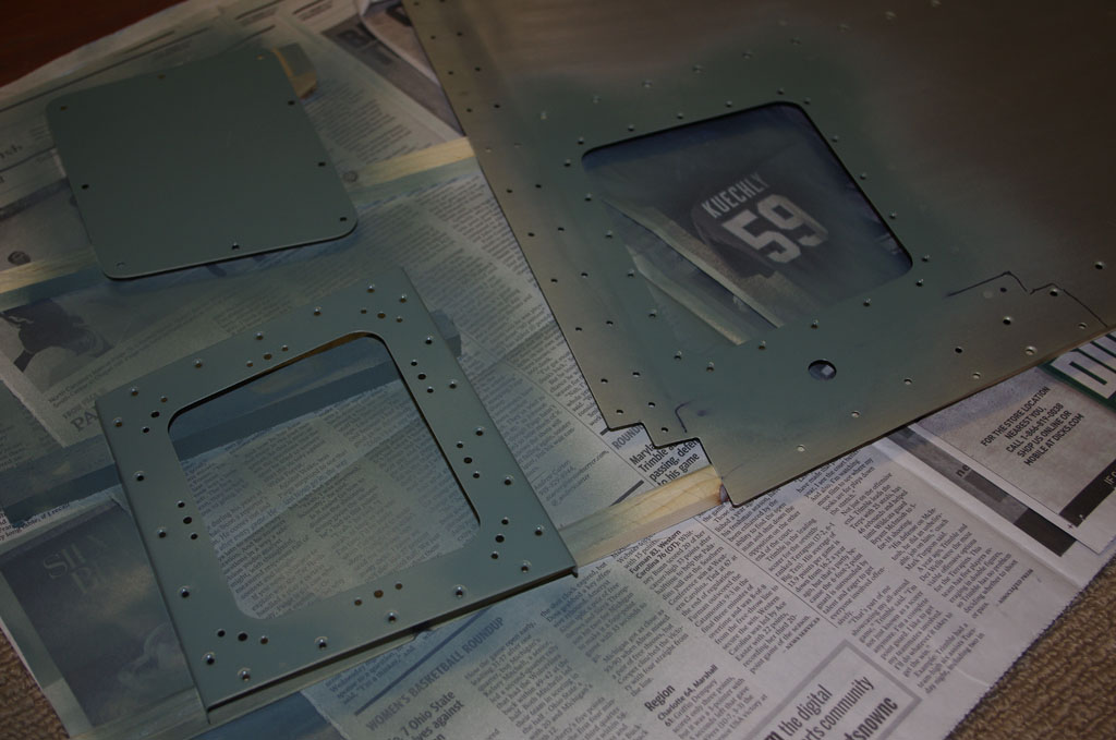
First a picture of the rough outline, then showing smoothed, primed and ready for installation.


IMGP6393
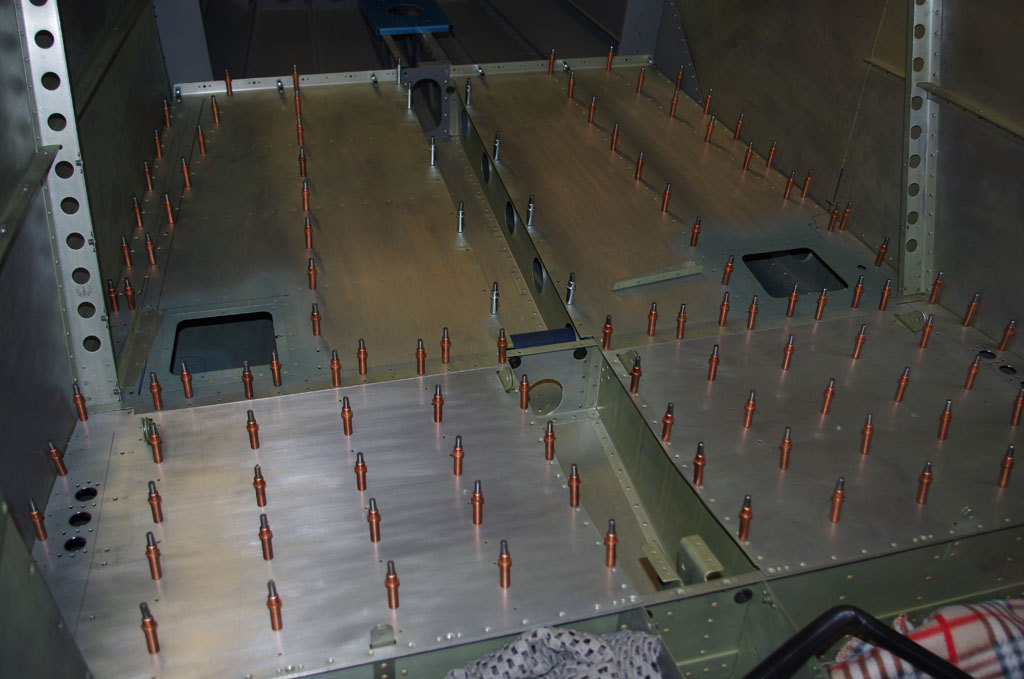
Voila.  This photo shows completed floor panels clecoed in position.  All the fabricated wire runs and inspection ports have been completed.  After months of working on customized elements for my particular configurations, I should soon be getting back to the standard plans.  Next up will be layouts of the baggage compartment panels.


Rear Wire Runs

Cutting pass through holes for 5/8″ conduit under the rear seat panels is no easy chore. With the quickbuild kit, the ribs are already riveted into position about 4″ apart.  Getting a large Unibit into proper alignement is impossible.  My method was use a right-angle pneumatic drill attachment to start a small pilot hole, then enlarge with a hand file to a size big enough to accommodate a knock-out set.

IMGP6346IMGP6349The set needs a 1/2′ pilot hole, then the first punch-out occurs by tightened the 11/16″ driving screw.  On the right is the rough opening for 3 conduit runs.


IMGP6350This shows the full circle first cut, then subsequent half-moon chunks taken out progressive to make the elongated opening for the conduits.


IMGP6362IMGP6357On the left side I made the backing plate first, then used is as a template to serve as a guide.


IMGP6366IMGP6365The second opening turned out much cleaner than the first.  Of course this will not be visible to anyone after the seat panel is pop riveted closed.


IMGP6368IMGP6369The pop rivet has a swivel head, but still there was barely enough room to operate. Slight flexing of both ribs was required to reach the bottom holes.


IMGP6372IMGP6375Final holes under the baggage floor have nylon grommets or conduit attachment brackets.

NAV Antenna Bracket (2)

After completing the oak prototype, a number of items were ordered for the final version. Blocks of acetal copolymer, 3/4″ aluminum bar, 5/8″ end mill, wiggler, some machines screw drills of various sizes, and a set of 3/16″ taps arrived for work on some precision equipment. My friend Tal is also building an RV10, so we decided to both use the same bracket design.  A few trips to another friends shop and access to milling machines and lathes was in order.

IMGP6301IMGP6302We used Tal’s bracket for the initial work, which started with using the lathe to round a 3/4″ aluminum rod down to 5/8″ to match the end mill (more on that later).  The lathe had fine adjustments down to 0.001″ and we came within a few thousandths of the mill diameter.


IMGP6297Next was milling the acetal block for the antenna rods. Here a wiggler is used to precisely measure the center points of the end mill holes.


IMGP6300This shows the block and the antenna rod matched together – near perfect for a pair of amateurs.


IMGP6307IMGP6309Now for drilling and tapping the rods for the actual antennas themselves. Note the special holding pieces in the vice I had gotten from Rich.


==================== February 6

Now that Tal’s bracket was completed, on to my shop for similar work. The rods had been made on the lathe beforehand, by shaping the acetal had to be done with my drill press.  This forced a slightly different approach than using the precision mill.

IMGP6314Here is the raw block with the planned outcome.


IMGP6319IMGP6320While not as accurate as the mill, my drill press is pretty good.  Using micrometers and the drill press laser guide, I was able to get close to the ideal dimensions on the rod holes on the side faces.


IMGP6326IMGP6329The through holes and corners were next. Again dimensions came out good. Note this was achieved using the X-Y drill vice also obtained from Rich from the estate sale previously mentioned.


IMGP6331IMGP6332The band saw and cutting fence were used to get the rough outer dimensions of the block.  A bit work on the bench sander and the sharp edges rounded nicely.


IMGP6340IMGP6341Drill the end and top holes.


IMGP6336Close to done.