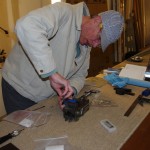
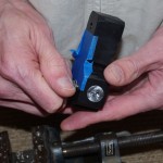
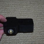
After completing the oak prototype, a number of items were ordered for the final version. Blocks of acetal copolymer, 3/4″ aluminum bar, 5/8″ end mill, wiggler, some machines screw drills of various sizes, and a set of 3/16″ taps arrived for work on some precision equipment. My friend Tal is also building an RV10, so we decided to both use the same bracket design. A few trips to another friends shop and access to milling machines and lathes was in order.
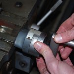
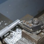 We used Tal’s bracket for the initial work, which started with using the lathe to round a 3/4″ aluminum rod down to 5/8″ to match the end mill (more on that later). The lathe had fine adjustments down to 0.001″ and we came within a few thousandths of the mill diameter.
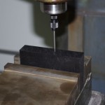 Next was milling the acetal block for the antenna rods. Here a wiggler is used to precisely measure the center points of the end mill holes.
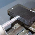 This shows the block and the antenna rod matched together – near perfect for a pair of amateurs.
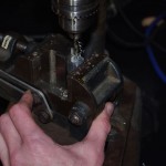
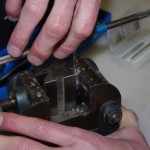 Now for drilling and tapping the rods for the actual antennas themselves. Note the special holding pieces in the vice I had gotten from Rich.
==================== February 6
Now that Tal’s bracket was completed, on to my shop for similar work. The rods had been made on the lathe beforehand, by shaping the acetal had to be done with my drill press. This forced a slightly different approach than using the precision mill.
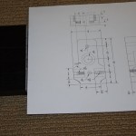 Here is the raw block with the planned outcome.
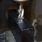
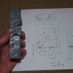 While not as accurate as the mill, my drill press is pretty good. Using micrometers and the drill press laser guide, I was able to get close to the ideal dimensions on the rod holes on the side faces.
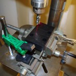
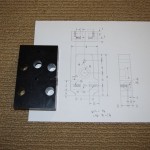 The through holes and corners were next. Again dimensions came out good. Note this was achieved using the X-Y drill vice also obtained from Rich from the estate sale previously mentioned.
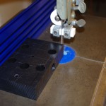
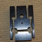 The band saw and cutting fence were used to get the rough outer dimensions of the block. A bit work on the bench sander and the sharp edges rounded nicely.
