Progress was made over the holidays by taking advantage of the social distance rules enforced in our area to focus on individual work.
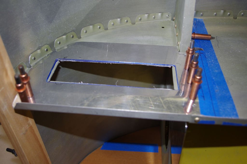
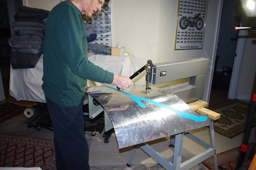
 The sub-panel was modified to accept the VPX-Pro electronic circuit breaker box. Here the raw opening was cut, followed by layout of the rivet and fastener holes for a backing plate.

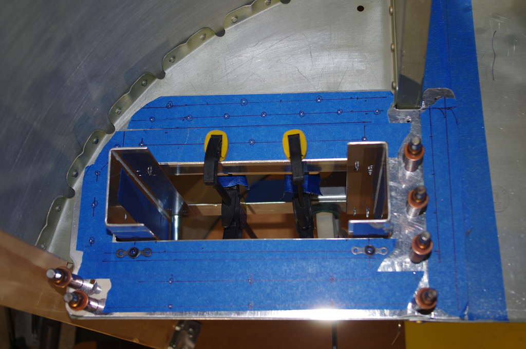
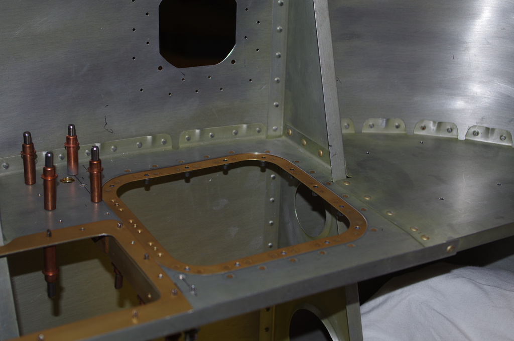
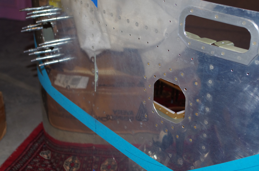
 The final holes for the VPX opening are drilled. The blue tape shows the future location of the primary and secondary voltage regulators (B&C LR3C-14). The untreated backing plates on the right picture were clecoed for test fits.

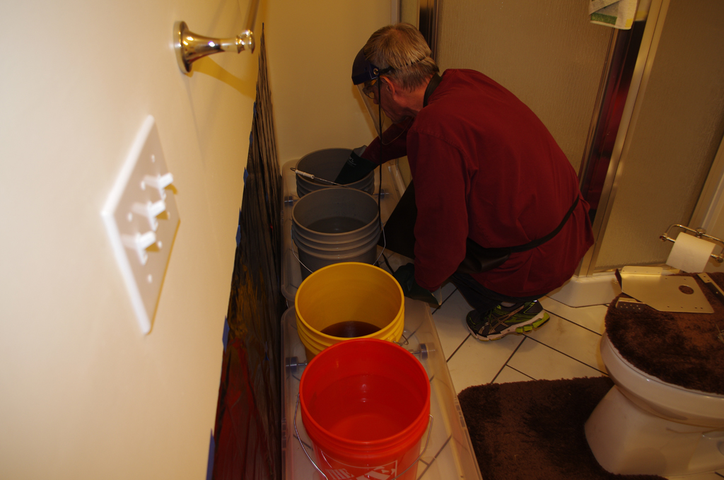 The backing plates and mounting brackets were prepared for the standard alodine treatment, which consists of scuff, degrease, acid wash, rinse, alodine dip, rinse again and hang to dry.
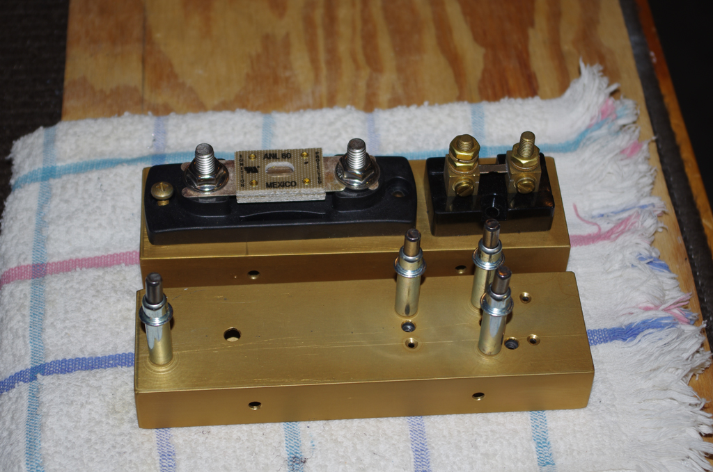
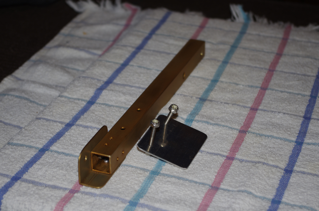
 The alodined ANL fuse/shut brackets are on the left. At right are the completed brackets painted Boeing 707 Gray and bolted together. Notice the copper bridge used between the ANL fuse and shunt. The raw bus bar stock of 1/8″ x 1/2″ copper is rated for 250Amps, plenty for this location. The bracket will eventually be mounted on the engine side of the upper firewall.
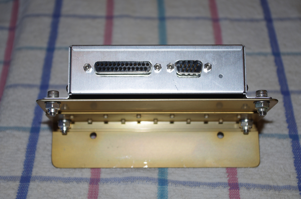
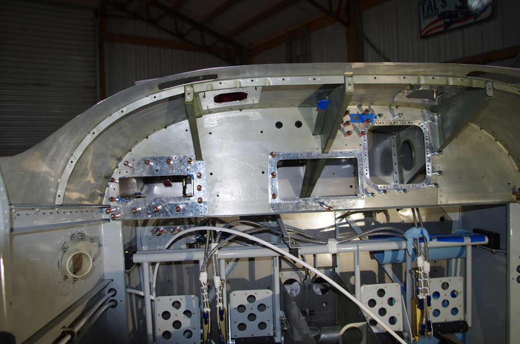
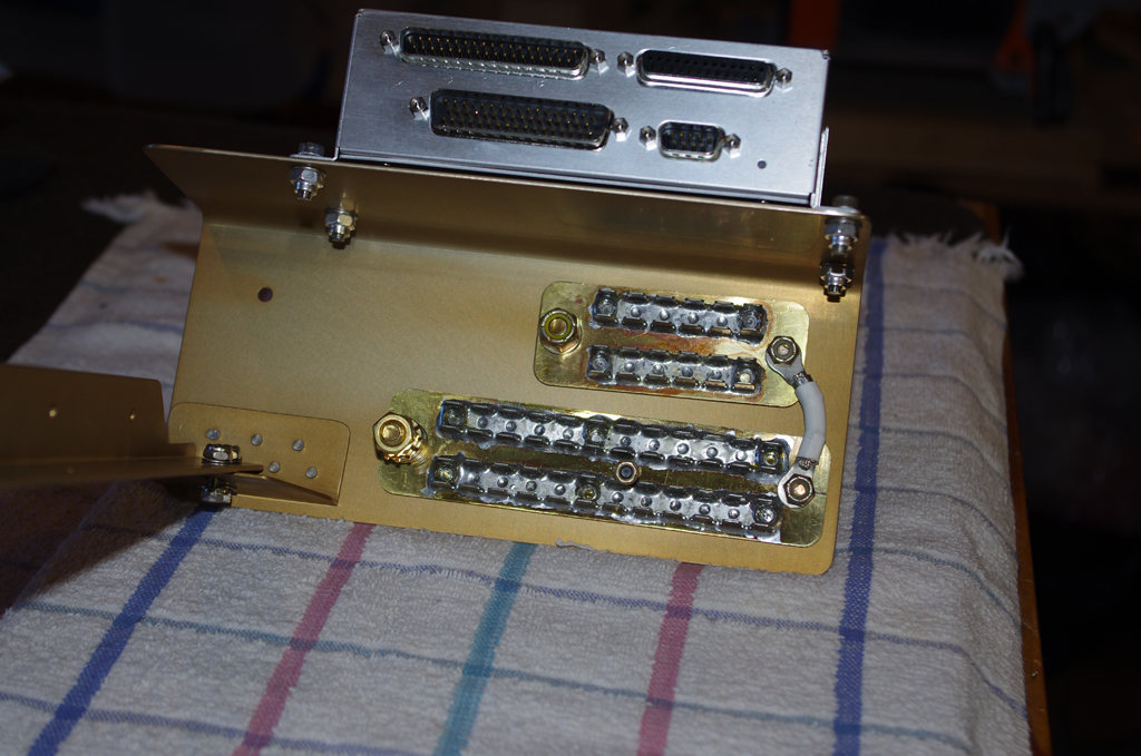 The cockpit side of the firewall will mount the GAD29 ARINC Adapter (left) and the GEA24 Engine Monitor devices. The GEA24 bracket also serves as the mount point for the B&C GB24/48 ground blocks.
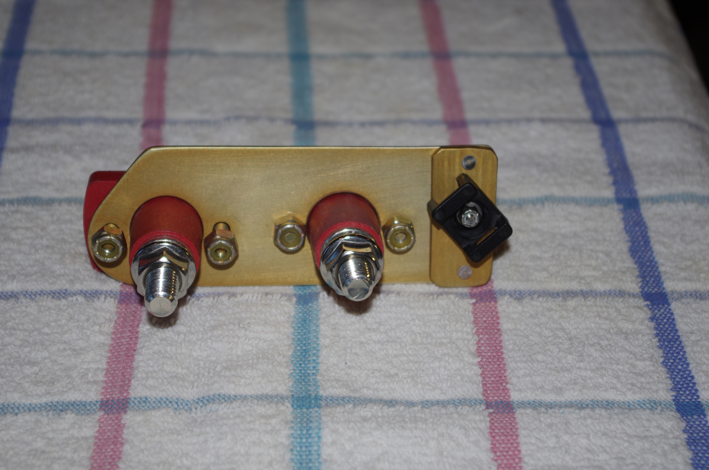
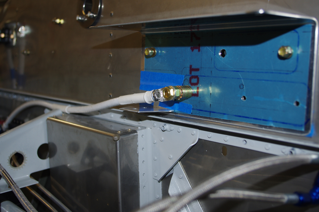
 Firewall penetrations for the terminal posts were supported by a backing plate. The nylon attachment point will secure the #2 wire from the GB24/48 ground block to the batteries which are located in the rear behind the baggage bulkhead.

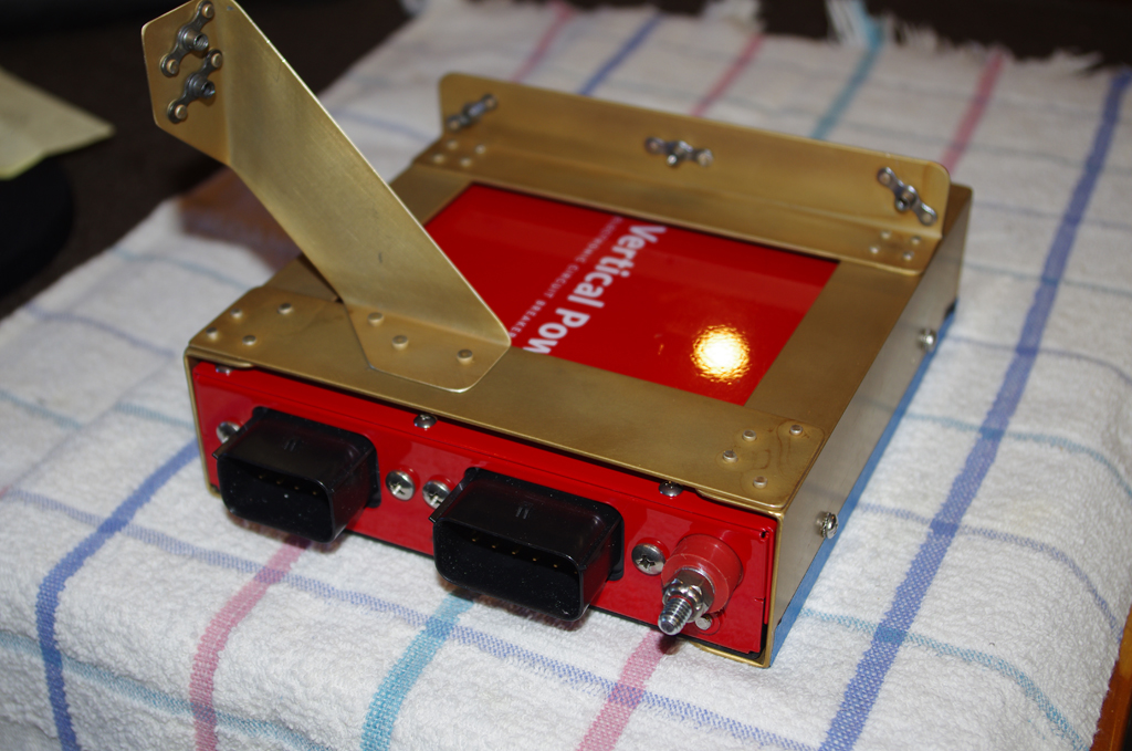 The finished VPX-Pro mounting bracket fits perfectly in the corresponding cutout in the sub-panel (shown above).

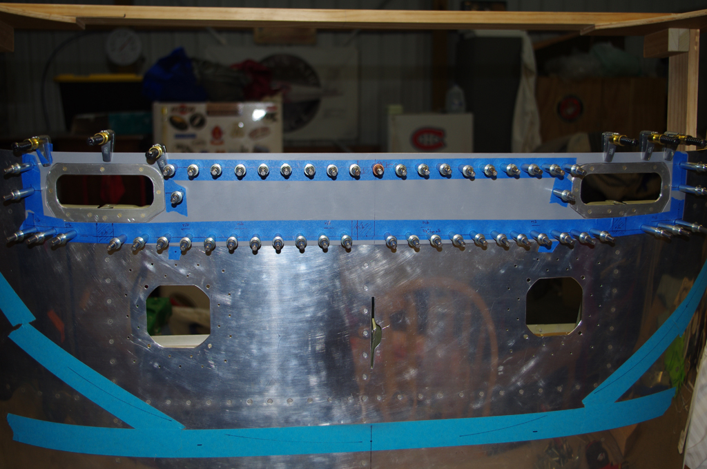
 The alodined backing plates were clecoed to the sub-panel prior to riveting. The right photos shows #8 nutplates being riveted onto the inspection port backer.
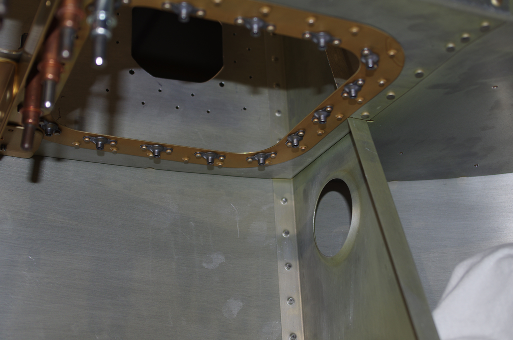 The inspection port backer riveted in place as seen from in front and behind the sub-panel.

 A reinforcement plate was fabricated to strengthen the VPX-Pro cutout hole and provide a mounting point for Adel clamps to secure cabling. On the right the DRDT-2 was used to dimple the dashboard for the panel fan backers.
 The panel fans will be 80mm brushless computer fans with a high cfm ratng. They are very loud at full power, but speeds will be adjustable for correct cooling by a rheostat on the panel.

 The dashboard skin is very thin (.032″) near the handle grips. To help strengthen this area for routine operations, a fiberglass reinforcement piece will be added.
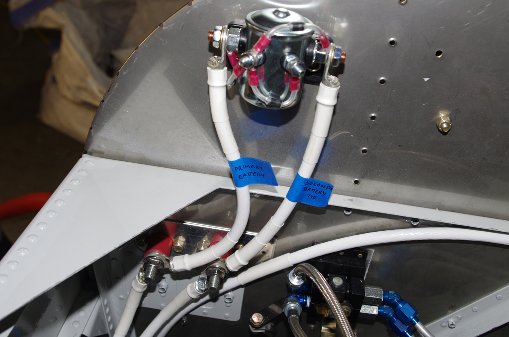
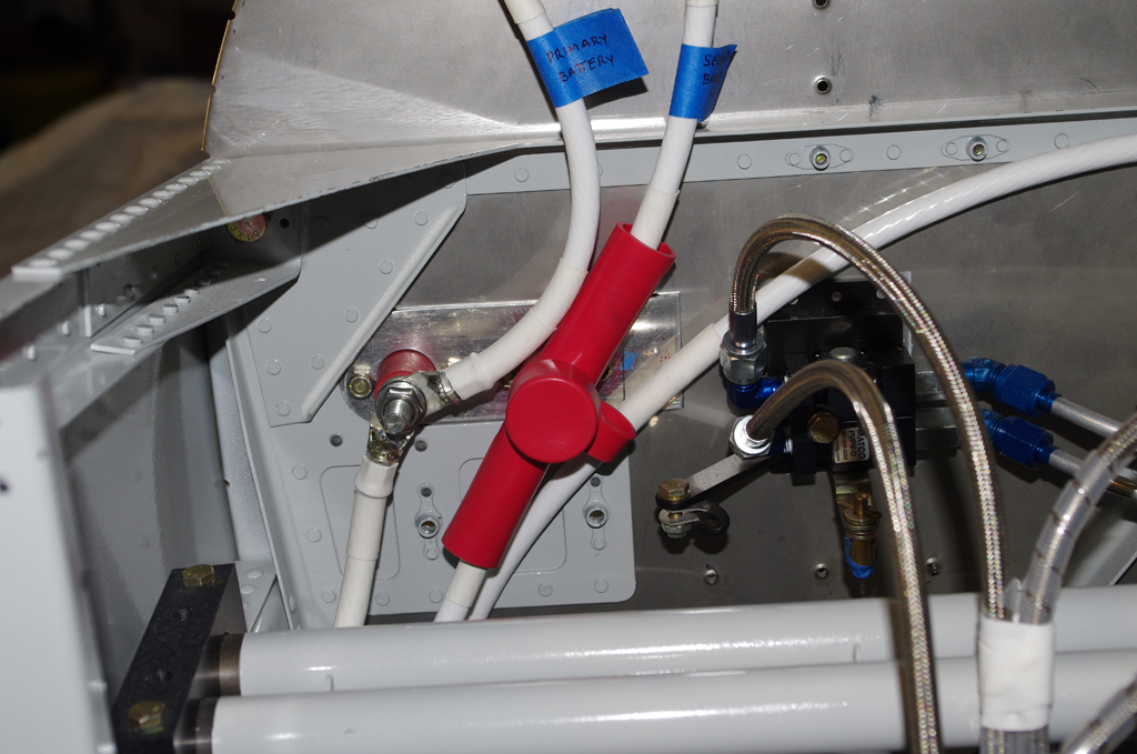 The primary and secondary circuits from the rear mounted batteries to the firewall terminals use #2 wire. The terminals are also attached to a cross-tie contactor – the single joint connection point between the two separate buses. A test fit of a tee-shaped boot shows how the terminal posts will be insulated.
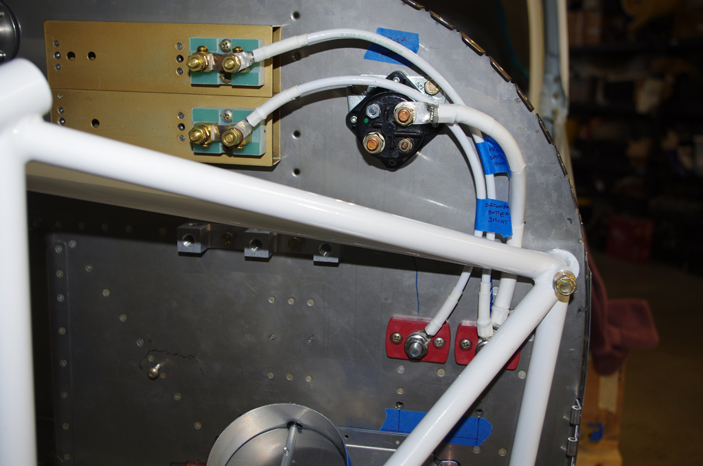
 On the engine side of the firewall the terminal posts connect to the starter contactor with #2 wire, and to the shunts with #6 wire. The right photos shows the #2 ground wire on the cockpit side bolted to the GEA24 mounting bracket.
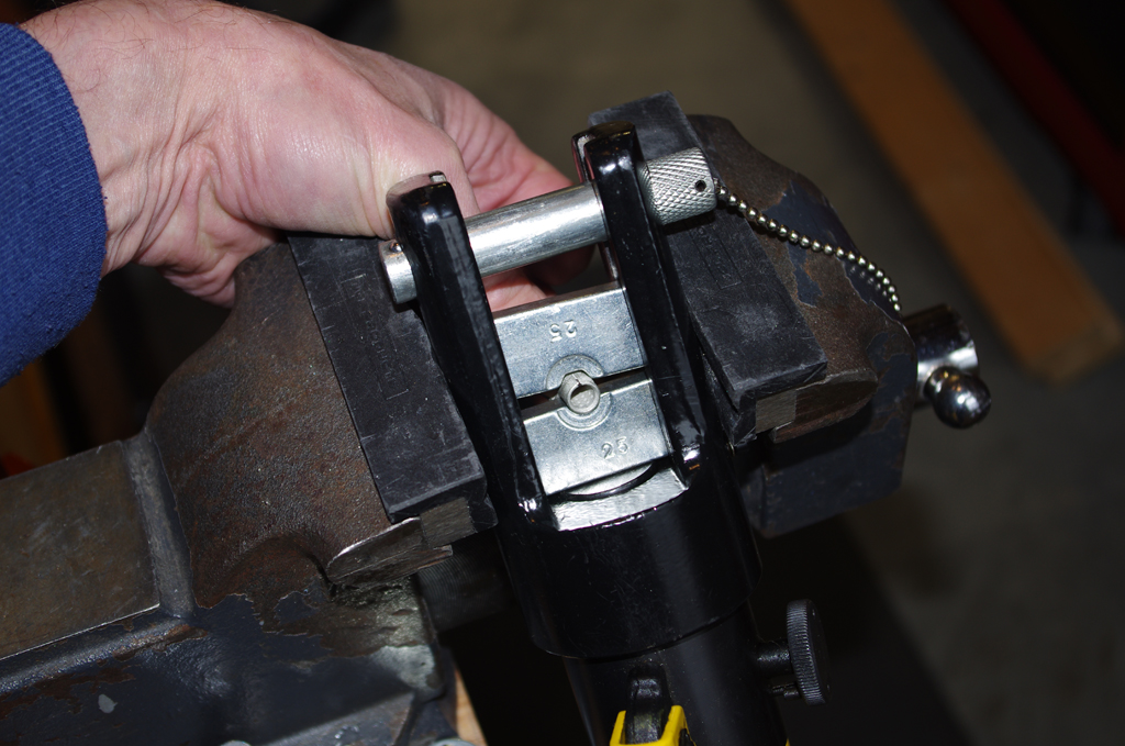
 The large #2 battery wires were crimped with a YQK-300 16ton Hydraulic Crimper. At the recommendation of electrical experts in the community the terminal lugs were lightly soldered at the tips just to secure an electrical connection to the wire. The solder should not wick into the flexible wire area as the heavily crimped section should be cold fused together to prevent penetration. At least that is the theory…
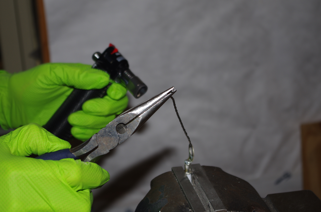
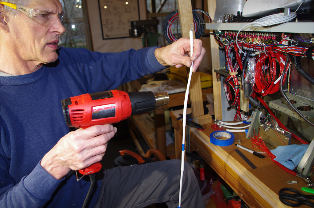 Completed terminal wires were heat shrink wrapped for insulation and protection.
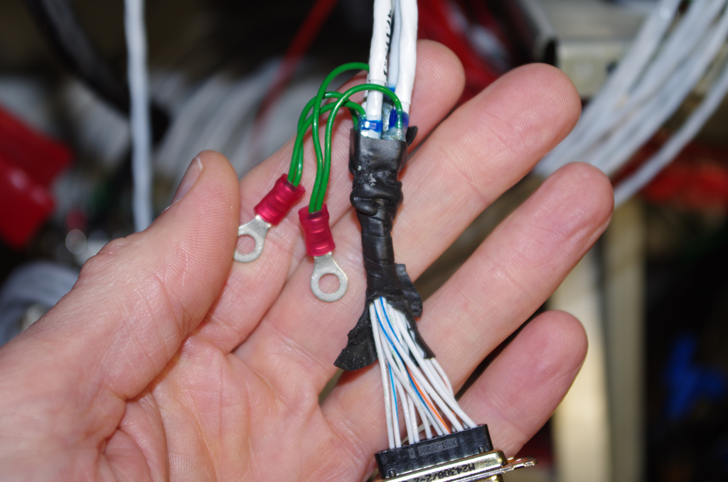
 Because the default wire for GTP59 Outside Air Temperature probe arrived too short to reach an appropriate mounting location in the left wing, the default termination to the GSU25 ADAHRS unit needed to be replaced with a longer wire. Prior to the re-pinning effort, the DB15 configuration was photographed. The extracted J252 Pins 1,2,3 were then replaced with new wire.
 A common termination point for aircraft ground wires near the instrument panel provides a direct, high quality electrical pathway back to the batteries. In addition, the colocation of labelled wires will help future troubleshooting activities.
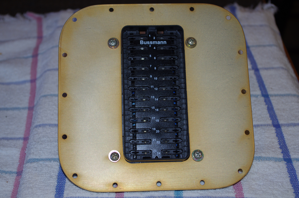
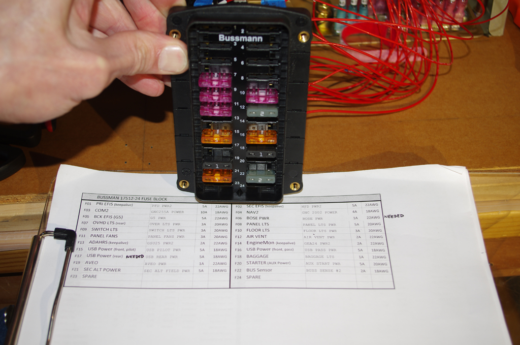 The sub-panel inspection port serves a dual function as being the mounting location for the secondary bus fuse block (Bussman 17512-24). On the completed fuse block ‘dumb’ devices (panel fans, floor lights, overhead lights, etc.) are bench tested with a 14.4V switching power supply. So far, so good.
Next steps are checking wire runs and functions on the main G3X devices and avionics.