Category Archives: Section 09, Elevators

Elevator Assembly (2)

This week saw final riveting on the hinges, trailing edges, rib tips, and bending the leading edges.

IMGP4733
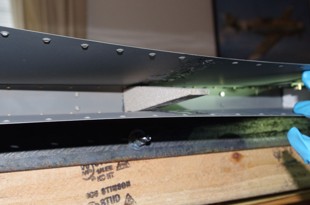
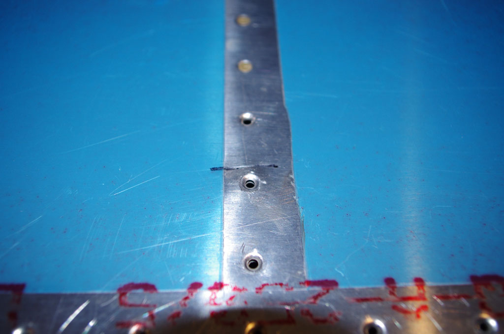
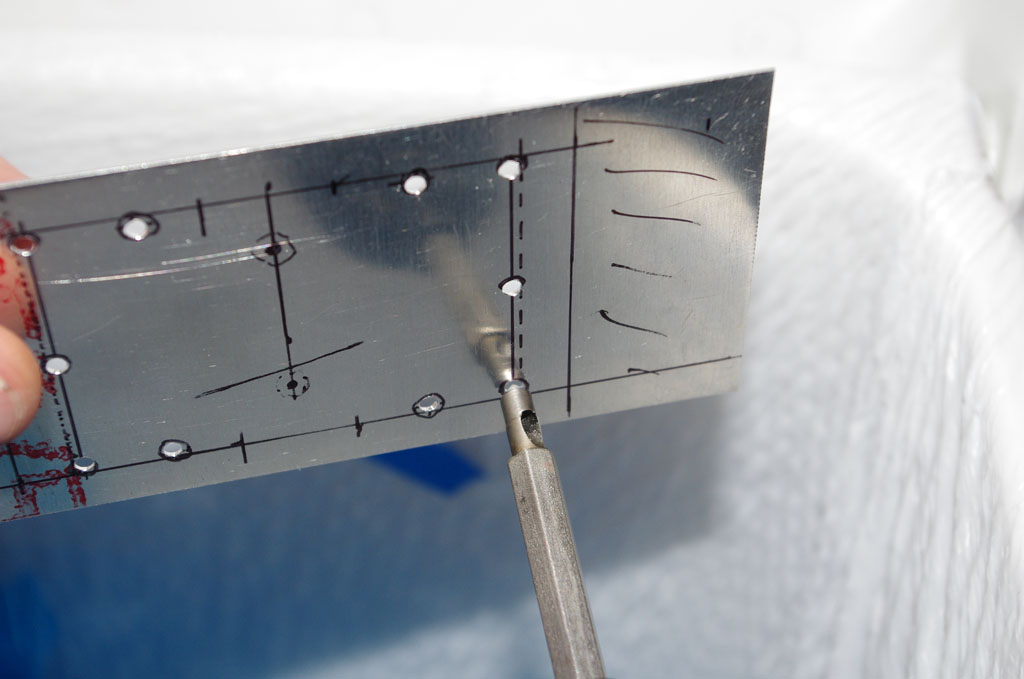
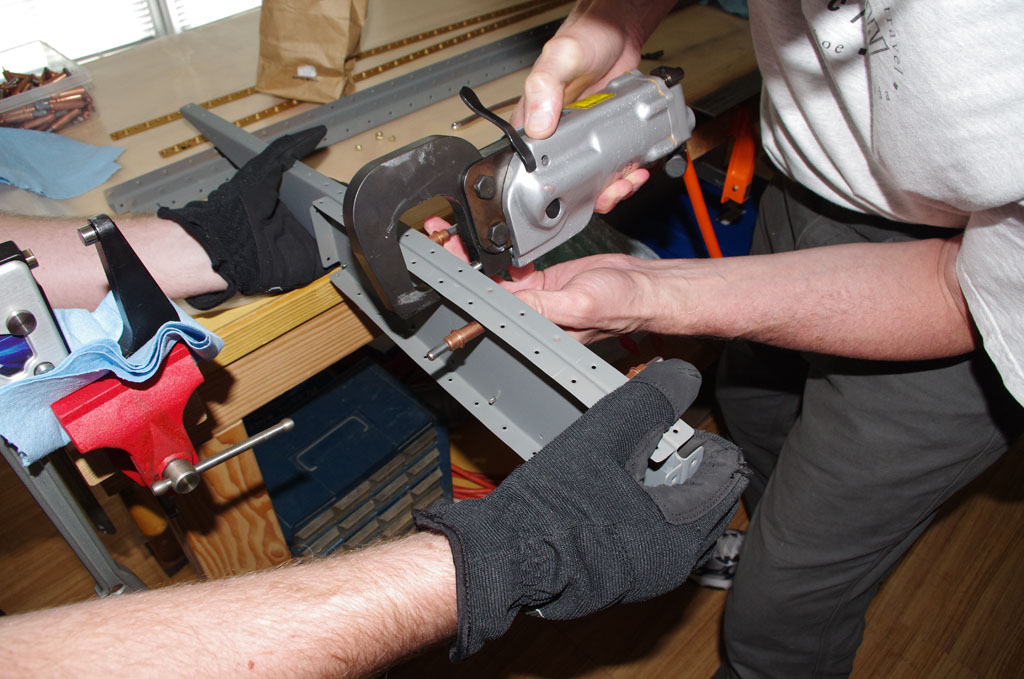
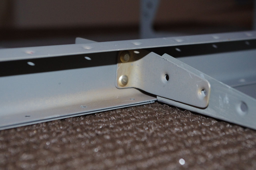
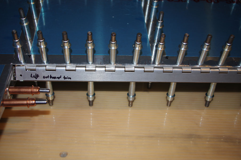
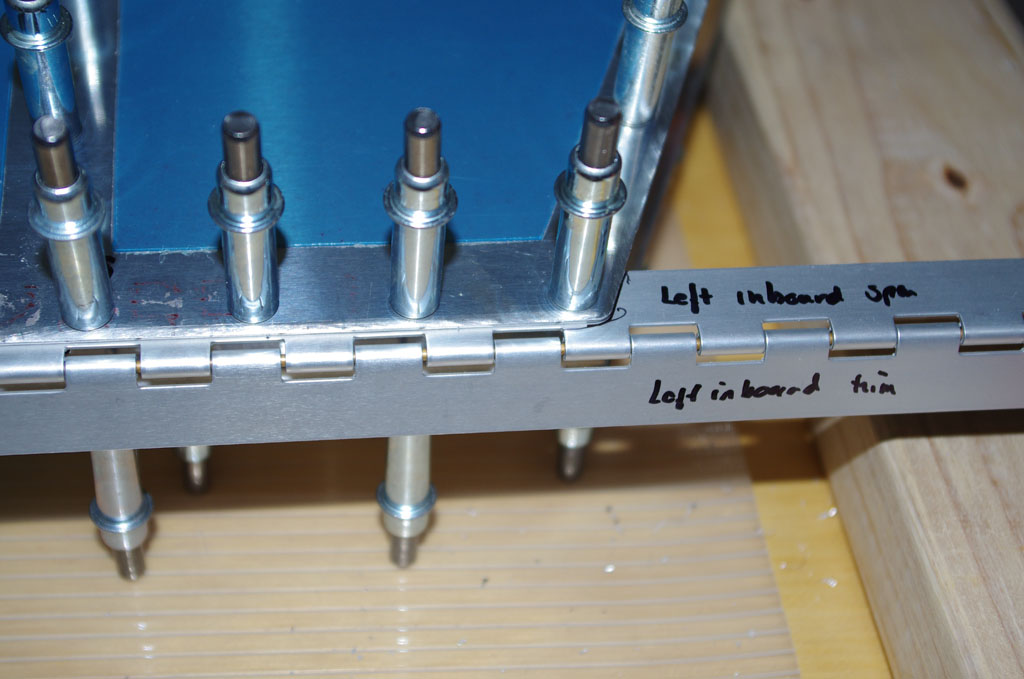
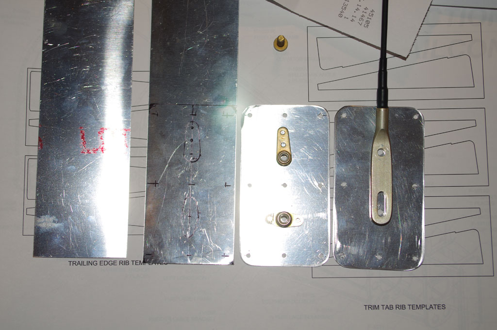
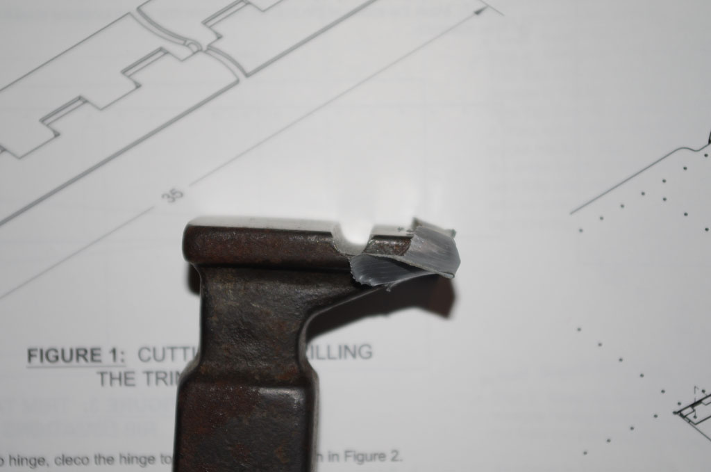
A special modification to a standard bucking bar was made with a grinder and round file. The depression in the bucking bar face exactly matches the trim tab hinges.  This configuration allow bucking the hinge rivets without smashing the hinge assembly itself.  The bar worked well and the results look good.


IMGP4739
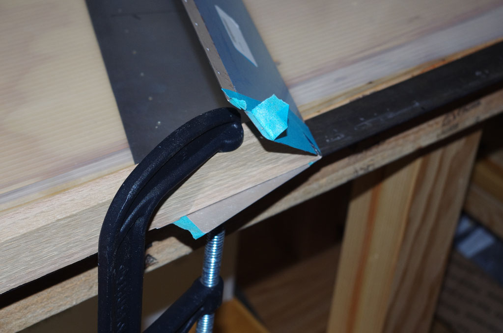
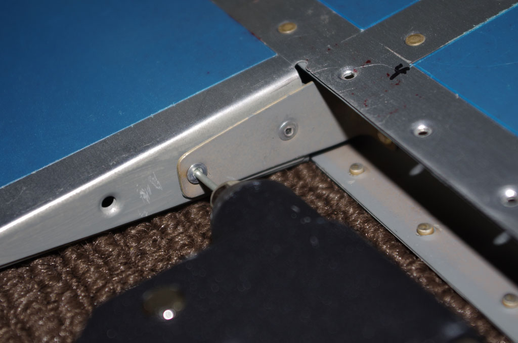
Here is how the modifed bar fits under the hinge to access the rivet for bucking.


IMGP4748
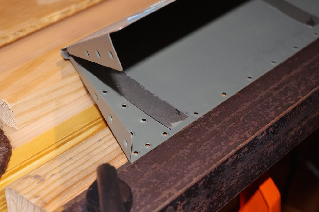
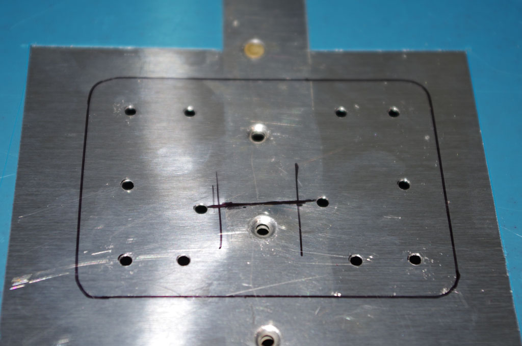
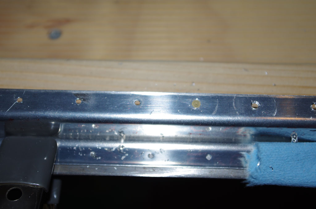
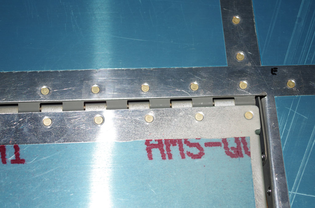
The final product looks good.


IMGP4725
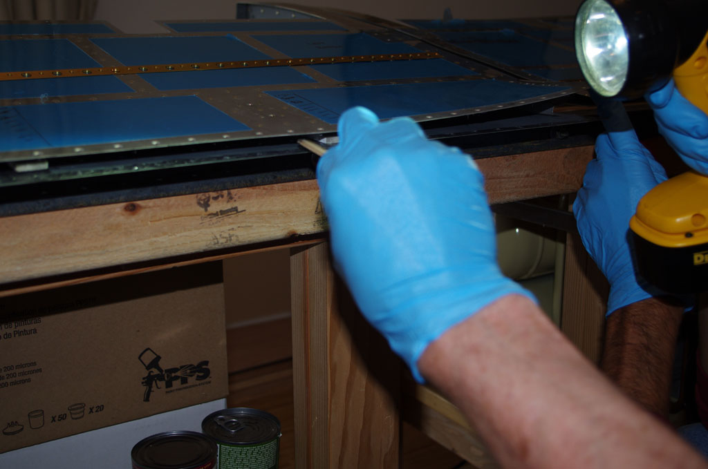
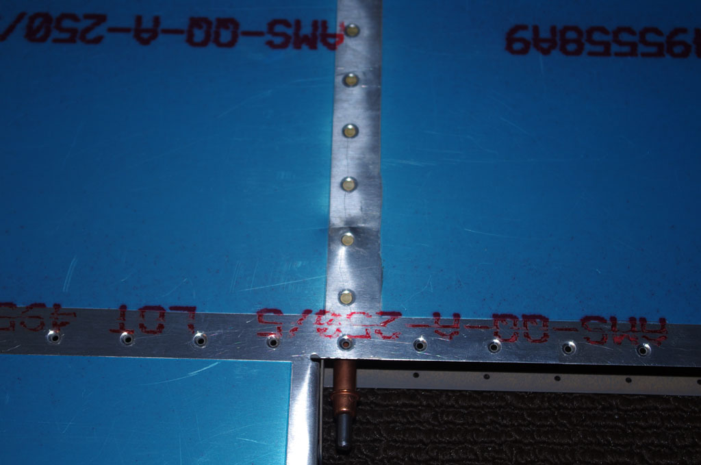
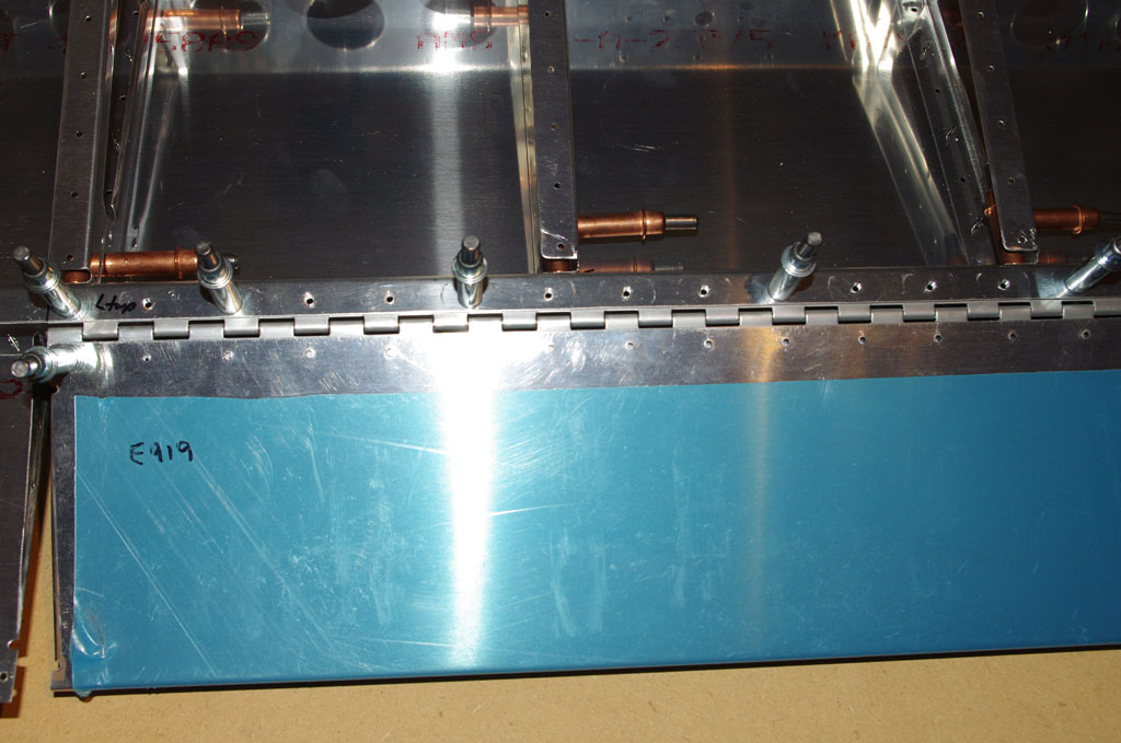
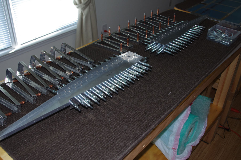
Next came backriveting the trailing edge.  This process was the same as for the rudder, with the exception that all the manufactured heads are on the top skin (no altering top and bottom).  I was able to do this by myself.  Again the results look good.


IMGP4726IMGP4728
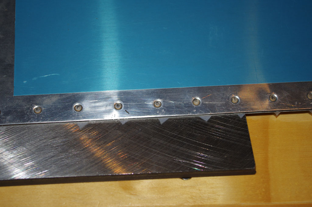
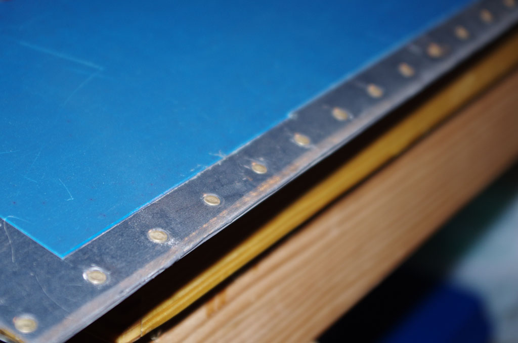
The outcome on upper and lower edges.


IMGP4731
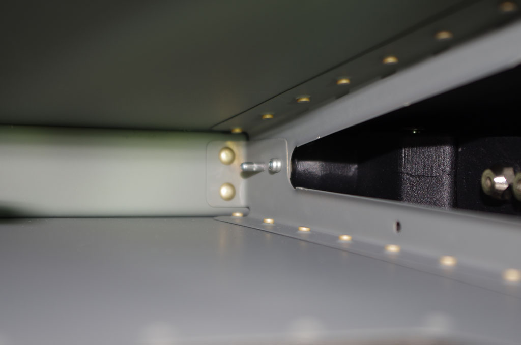
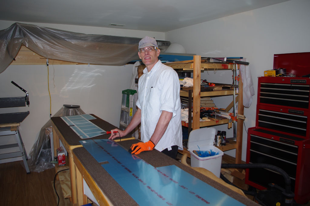
Here the sheer clips are being pop riveted into place.


IMGP4736
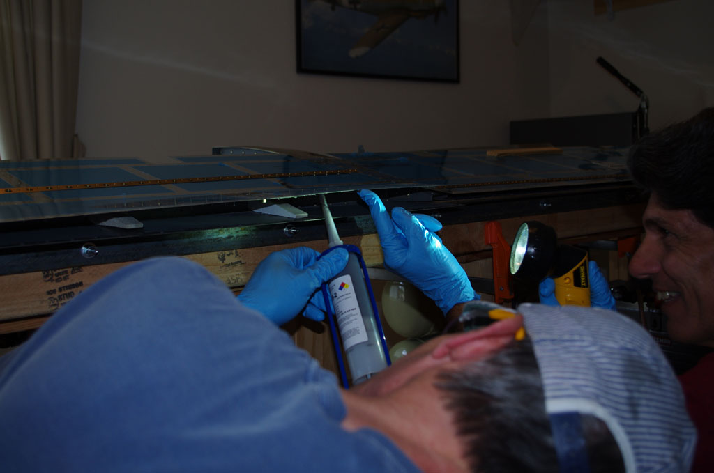
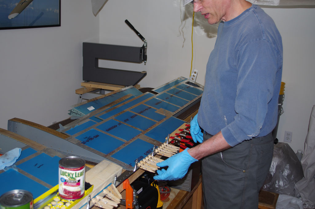
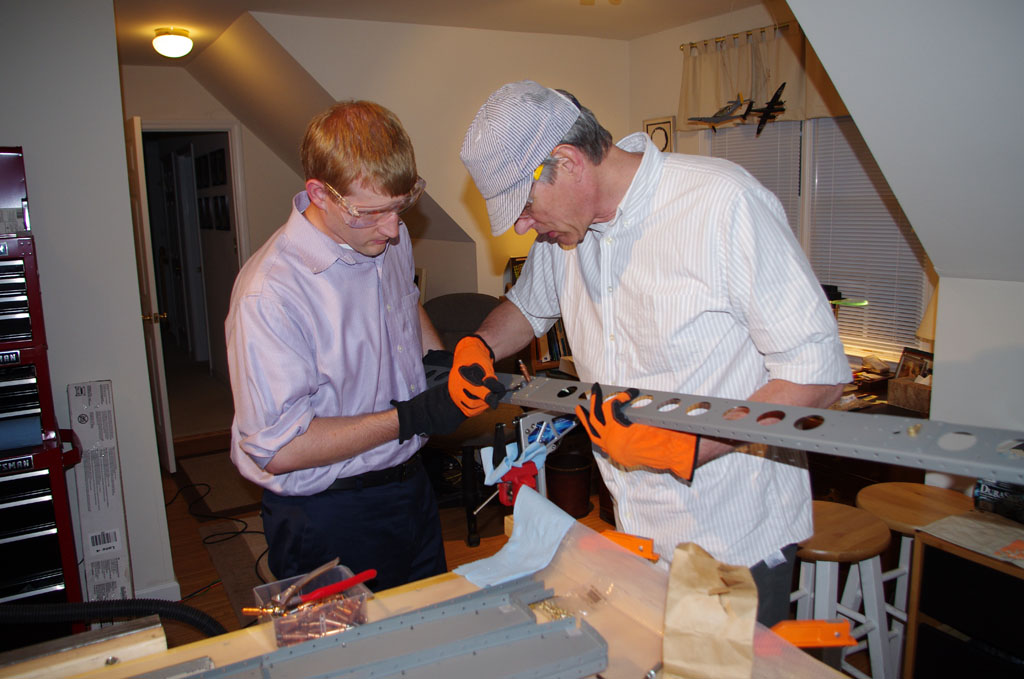
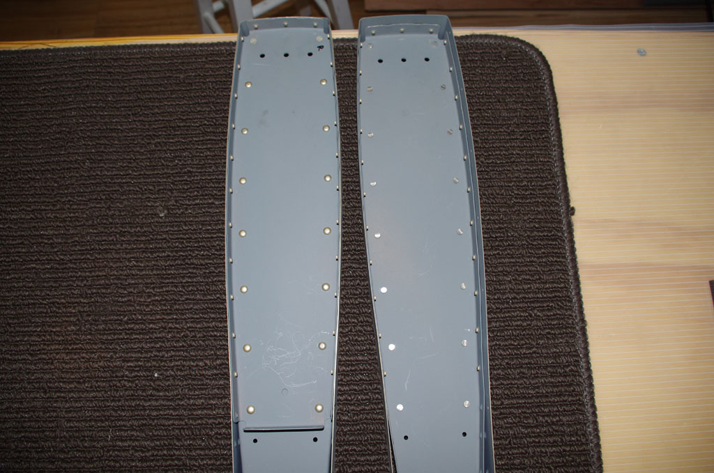
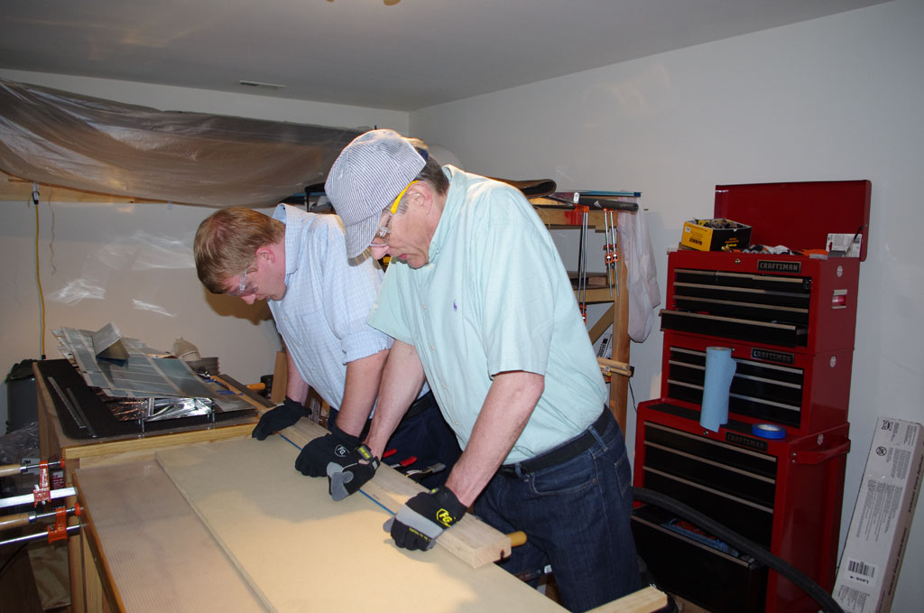
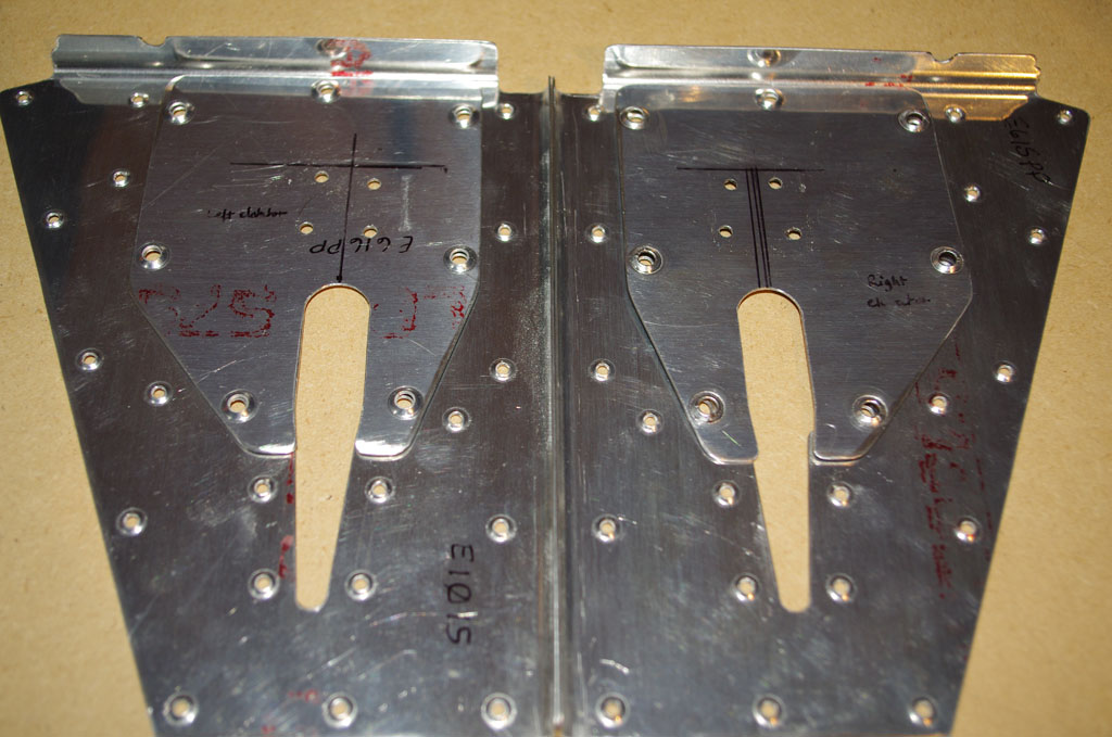
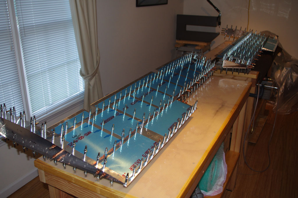
After rolling the leading edge of the right elevator with Rich’s help, we cleco the two halves together.  We were only able to complete the left side with the time available today, but the final work on the right side will be done in a day or two.  More photos of the final product will be added later.


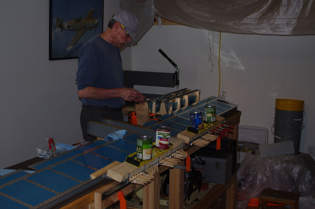
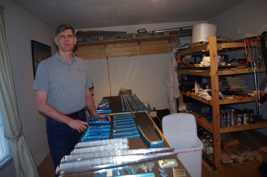
The week of November 24 (Thanksgiving Holiday) I spent time with Eric finishing up all elements of the elevator build.

IMGP4756IMGP4758
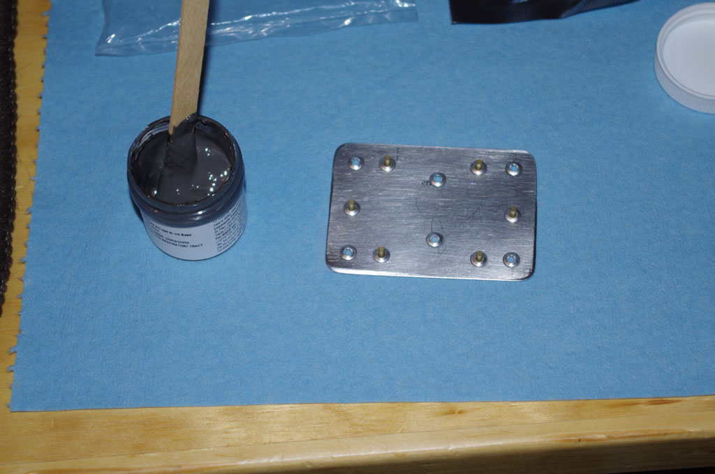
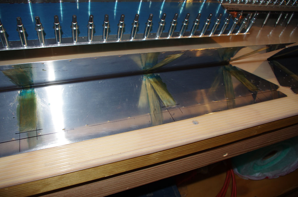
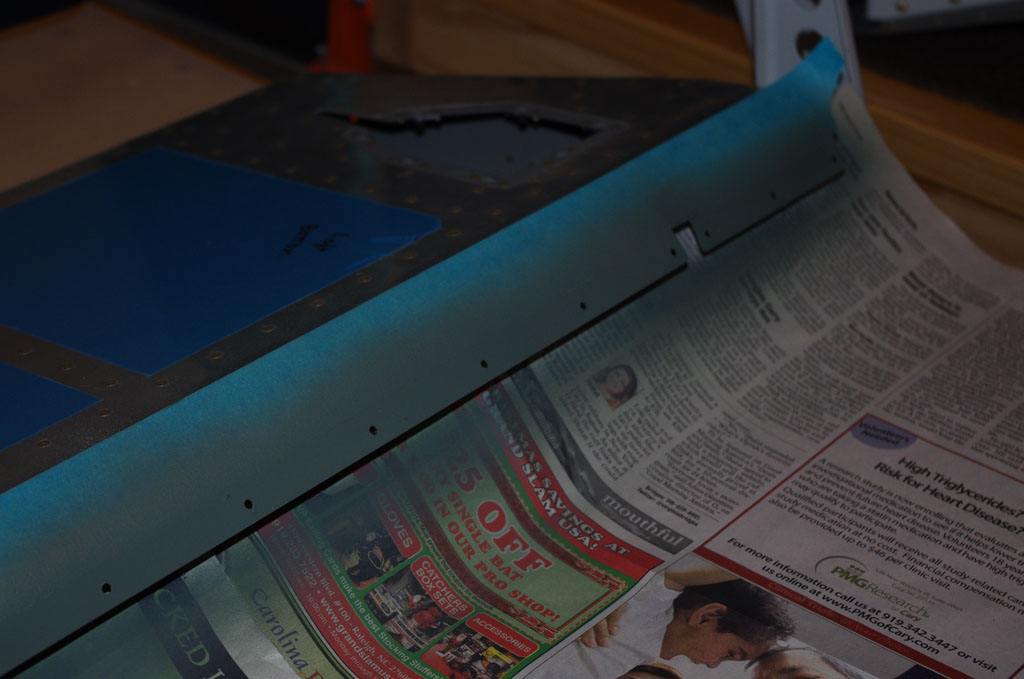
After rolling edges, priming the surface to be covered was the next order of business.


IMGP4746IMGP4754Closeup of the final product before and after pop rivets.


IMGP4740
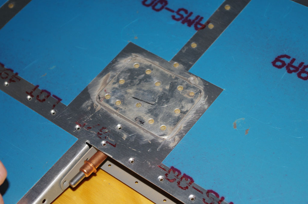
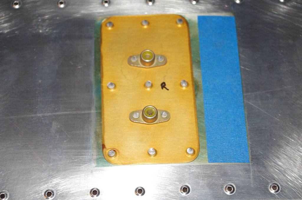
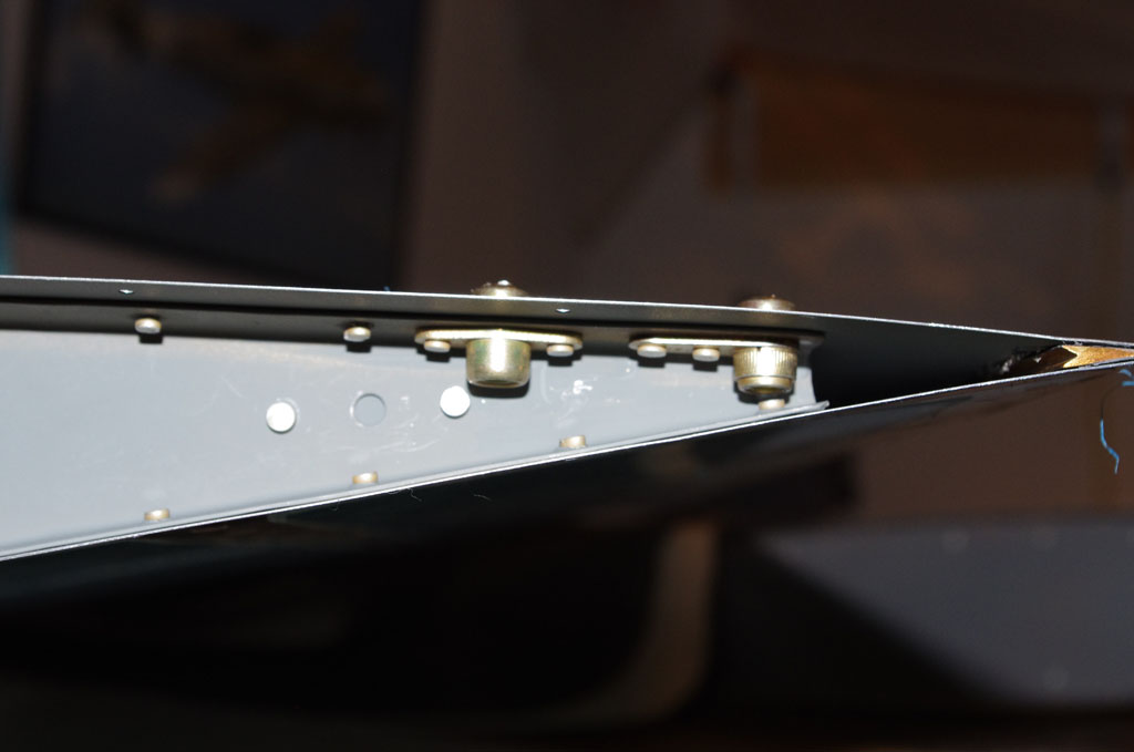
The static wick nut plates install on the lower skin at the tip ribs.


IMGP4752
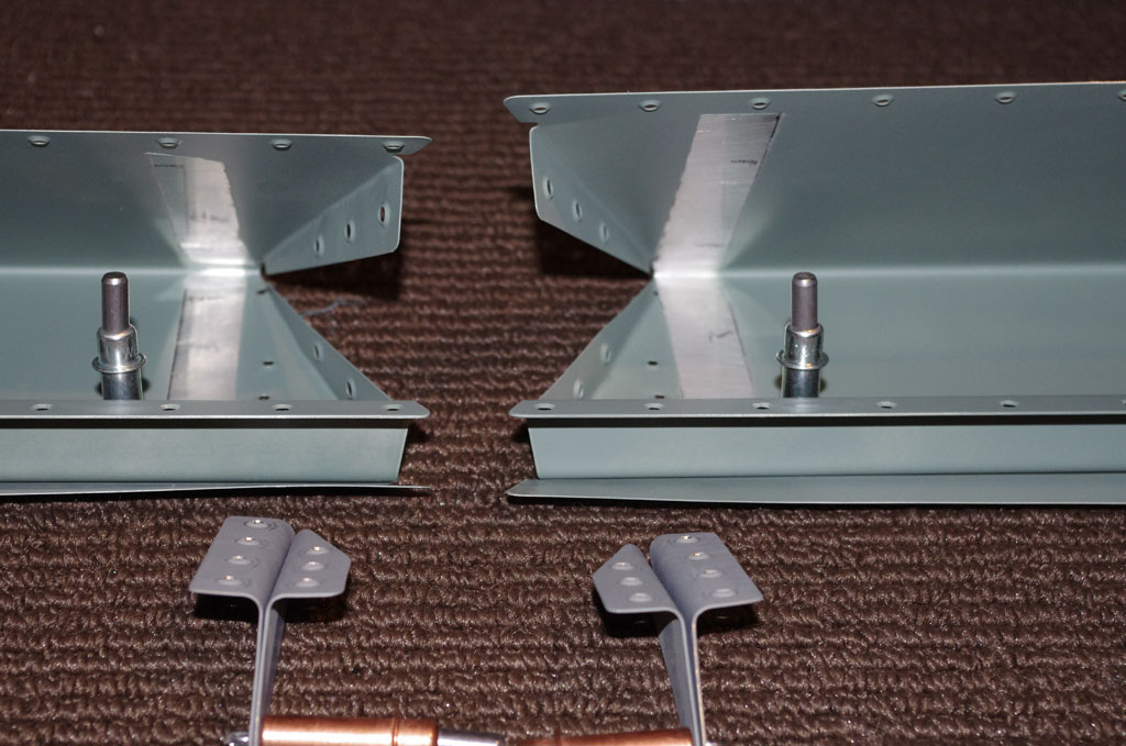
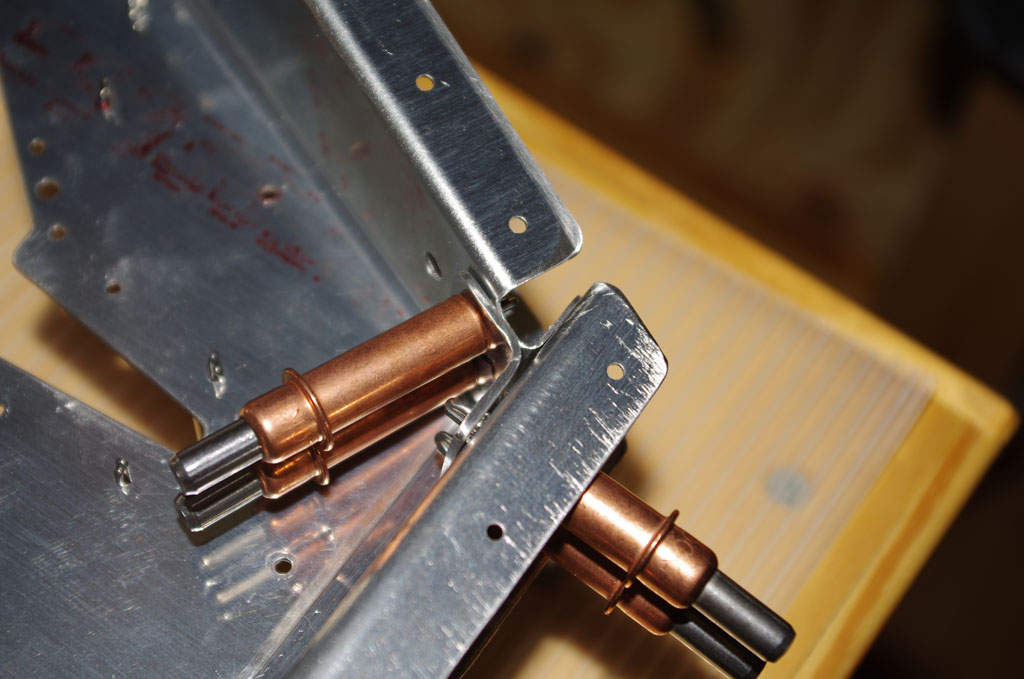
Tip rib counterweights installed.


IMGP4760
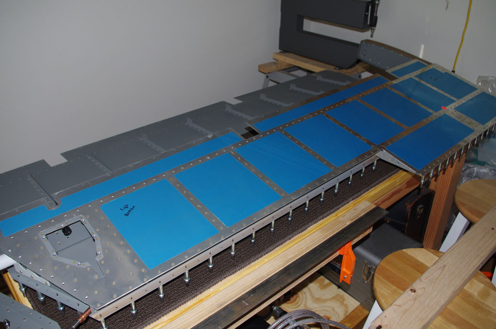
End results! They look good at a distance, but I really struggled through the elevators (see previous posts).  Now on to the tail cone section.


Elevator (Bonding)

After many weeks of redoing the elevator trim tabs, adhesive bonding of the trailing edges and foam ribs was in order.  Rich came over to lend an extra pair of hands during the process.

IMGP4681IMGP4682Bending the angled trim tabs was accomplished with a simple red oak board cut to a 45 degree angle, then clamped to the angle iron jig.


IMGP4696Here the trim tab is sandwiched between two pieces of angle iron for bending the front part of the lower skin to 15 degrees.


IMGP4697A 12″ back rivet set was used with a standard backing plate to attach the lower portion of the trim tab spars.


IMGP4701Here is how the first set of trim tab horn rivets appear. More on the trim tabs later.


IMGP4703Cherry Max 3213-4-3 structural rivets were used to replace the simple LP4-3 called out in the plans. Discussions with my technical counseler and an A+P mechanic indicated structural rivets can always be substituted for lower strength rivets of the same size. However, Cherry Max brand rivets are more expensive (about 63 cents apiece).


IMGP4711IMGP4706On to the trailing edges – here the Van’s ProSeal equivalent is being applied initial application from with a caulking gun.  I later used a wooden popsicle stick to smooth out to ensure complete coverage.


IMGP4708This shows the foam rib attached to the rear spar.


IMGP4714Smoothing out the  bonding adhesive, getting ready to insert the trailing edge.


IMGP4715The trailing edge is clecoed to the angle iron jig about every 7th hole.  In between are wooden clothes pins, then comes a 2×4 with weights to hold the skins against the freshly bonded foam ribs.


IMGP4718The trim tabs were also bonded.  This photo shows them in the wooden jigs holding the skins against their bonded foam ribs.


IMGP4719DONE.  Now to let the adhesive cure for a few days before starting the final riveting steps.

Elevator (Skin Repair)

This week I consulted with Terry Gardner on the best approach for handling the skin crease in the lower right elevator skin.  Just proceeding ‘as-is’ was one option, provided continual awareness of any crack development over time.  After considering alternatives, we decided to apply an external patch, drill out the adjacent rivets, stress relief holes, provide some bonding with a thin layer of ProSeal, and then apply new structural rivets all around.  Essentially this approach sandwiches the weakened crease line between the new patch and the internal rib. This may seem like a touch of overkill, but worrying about potential cracks on a new plane did not seem an attractive alternative.  Plus the time is right – the right elevator is basically wide open, I can get to both sides of the skins, and using structural rivets is preferred to Cherry rivets applied later.

Here is the effort for the week of October 5-11.

IMGP4571Another look at the offending location…


IMGP4572Pattern laid out to fabricate the patch.  Here I am using a scrap piece of .025″ aluminum.  The skin itself is .016″, so this should be adequate and easily use an AN426AD3-4 rivet for proper thickness.  The Advisory Circular AD43.13 page 4-20 was used to determine proper rivet separate for this plate (three diameters between centers).


IMGP4575Using the drill press to fashion the plate holes.


IMGP4577Deburr the holes with a hand-held cordless screwdriver and about 120rpm.  Notice the right hatching, this will be removed in the next stages to get the proper outer dimensions of the patch.


IMGP4586Used the patch as a template for first match drilling the skin holes.  Here piece is clecoed to the skin.  Not all the holes have been drilled in this picture.  Example, the lower left hole is clearly visible in white.


IMGP4590Here is how the skin looks after match drilling all the holes with the patch and the adjacent rivets removed.


IMGP4597This picture shows the stress relief holes drilled at the ends of the crease.  A #40 drill was used.  Fortunately the crease line is very well defined, not diffuse across the skin.  Next up is dimpling, bonding and riveting.


IMGP4584I had a little time available after skin drilling, so I started in on the rebuild of the trim tabs.  Here a jig for holding the rough-cut elevator horns is depicted (next to the roughed out patch plate).


Week of October 20 – A business trip to LA consumed over a week of my time. Before leaving I ordered a small one ounce quantity of ProSeal equivalent from Van’s for bonding the patch to the skin.

IMGP4611This stuff looks and smells just like the branded ProSeal version.  This container has a one hour set time, so moving expeditiously through the process is required. The white bottle contains the main compound, the foil pouch has a black colored catalyst.  The instructions call for uniform mixing with the wooden stick, and the final outcome should be a dark grey.


IMGP4612The mixture did turn dark grey.  The stuff is very sticky and quite thick, which made it difficult to spread thinly or evenly on the pieces. The patch has some of the rivets held in place with rivet tape for alignment with the holes in the skin.


IMGP4613Smeared and ready for back riveting.


IMGP4618IMGP4624Well here it is riveted, and then cleaned up.  Not too bad.  The final cosmetic verdict will be once primer and paint are applied.  My feeling is the structural elements of the patch are very solid.


Elevator Assembly (1)

Upon return from vacation I started the assembly of the elevator parts.  All went well until …. (more on that later).

IMGP4526Elevator reinforcement plates on inital assembly.


IMGP4533Adding the hinge reinforcement plates (those not already installed with the bonding strap nut plates).


IMGP4539Using a pneumatic squeezer and longeron yoke borrowed from Tal Halloway, a fellow RV10 builder.  The longeron yoke configuration is needed to get at both sides of the tip ribs.


IMGP4547Completed tip ribs, shown front and back.


IMGP4552Here it is – my big mistake on back riveting the lower right ribs to the skins.  Despite much care in alignment, the rivet head vibrated off the side of the backing rivet plate, resulting in me pounding the **** out of  the skin. Looks bad, thought skin was not broken.  I will have my technical counselor advise on path forward for this error.  In the meantime, I completed the left side back riveting with very good results.


IMGP4555Sheer clip install on left rear elevator spar.


IMGP4564Pop riveting the upper and lower left skins together with the ribs.  I used an old mouse  pad under the pop rivet tool for proper vertical alignment and keeping the tool from scratching the primed surfaces. The outcome was excellent.


IMGP4566The left side assembly through riveting the rear hinge is completed.  Again this part looks very good.  We shall see how the right side proceeds.

Elevator Prime (Complete)

After work this week we finished off the Prekote and prime of elevator skins.  The most significant elements were masking off the scuffed area for foam ribs, and priming the riveted reinforcement plates for the static wicks.

IMGP4444Ready for primer…


IMGP4446Done.  Next step is rivet assembly.


IMGP4447All the elevator parts primed and staged for assembly.  Rita and I are taking vacation in the NC mountains this coming week, so maybe a few rivets will get set over the weekend when we get back.


Elevator Prep (Alodine/Prime)

I took a half-day from work on Friday, then spent about 15 hours over the weekend with the routine for wash, scuff, brighten, rinse, alodine, and priming all parts except the skins.  The process is the same as described in previous posts.  Here are just some pictures of recent events.

IMGP4435IMGP4424This photo shows the reduced cross-section on the special female 3/32″ die purchased from Cleaveland Tools.  Here the clearance from the screw recess is visible.  A picture of the regular die size is included for comparison. (see previous post on details)


IMGP4437Alodine applied to the skins where foam ribs will be glued with ProSeal.  This process is the same used for the trim tabs.


IMGP4439The garage is turned into a chemistry lab for the weekend…


IMGP4442Happiness is when friends and family participate in your favorites hobbies.  Rich and Eric both helped greatly on a long, hot weekend of metal prep and priming.

Elevator Preparation (3)

This Labor Day weekend, Eric and I spent about 16 hours working on spars and skins. This took most of the time, but a few other activities showed progress as well.

IMGP4398Scuffing the insides of the trim tab skins is necessary for a good bond with ProSeal at final assembly.


IMGP4399Plans call for bare metal, but I feel a good alodine coat will help prevent any unwanted corrosion under the foam blocks. My approach was alodine the bonding areas, mask off these areas, and prime the rest. The primer should be sprayed on before the skins are bent to the 10degree final angle needed for attaching to the spar. (The bluish tint on part of the alodine is from the Sharpie marking lines.)


IMGP4408Here a SEM product (self-etching primer) is applied to the insides of the trim tab skins. Note the skins are still fairly far apart at this point.


IMGP4413After priming is when the final bending occurs.  Eric helps me apply hand pressure with a 2×4 on the trailing edge.  We had to do this 10-12 times as the skins wanted to rebound back to their original shape.  I had been advised by my technical counsellor not to be to aggressive with an acute bend – else the edges would crack.  Gentle, repeated, and steady pressure did the trick.


IMGP4419Bending the end tabs is also an adventure.  In retrospect, I would cut two oak boards and a 10degree angle for the bends. In addition a 1/32″ round could be applied properly to the oak wedges. This would dispense with the two sided tape, forward-backward slipping, and sharper than desired tab bend radius which occurred with these blocks.


IMGP4414After the bends, we fit and drilled the hinges to the trim tabs.


IMGP4428Countersinks are performed against the upper trim tab spar to accommodate a flush finish with the skin.


IMGP4433Here I use the Main Squeeze to dimple the trim tab skin.


IMGP4416Even using hand methods the results on the trim tab ends are not bad.


IMGP4422Here the angle iron jig is being used to hold the elevator trailing edges for countersinking.  I used this technique before on the rudder.


IMGP4423One of the trim cable anchor brackets turned out fine after dimpling.  The first reinforcement plate (right) was seriously misshaped by not aligning the DRDT machine correctly.  I have ordered a replacement part from Van’s, as all the pressure on the elevator cables is on these two pieces.  Live and learn…


IMGP4424The trim cable anchor brackets also have K1100-06 nut plates to accept the #6 screws holding the reinforcement plates.  Unfortunately the nut plates themselves need to be dimpled for the flush rivets. The default die set is too wide, and deforms the screw recepticle.  Cleveland Tools does sell for $19 a special low profile female die for exactly this function.  My order should arrive this week.

Elevator Preparation (2)

This week’s work centered around match drilling all skins and spars.  A number of miscellaneous small parts and jigs were also completed.

IMGP4380The gusset pieces in the corners reinforce the elevator at the rear spar and root rib junction. After the skin were clecoed in place, this whole assembly was very rigid, amazing for being made from such thin parts.


IMGP4386Here everything is clecoed together, ready for the evenings of match drilling of the skins to spars and ribs.  Eric helped on all these.


IMGP4392The trim tab has foam blocks attached with ProSeal compound instead of ribs/rivets like the rest of the elevator. The wooden blocks will be used to hold the skins in place against the foam ribs while the adhesive drys.


IMGP4395IMGP4396Here the hinge for the trim tabs are fitted and drilled to the upper rear spar flange. Eventually the excess length will be removed, but the extra pin length will be secured with safety wire.

Elevator Preparation (1)

Interim activities include preparing the trim tab, spars, and skins by fitting, match drilling, deburring and smoothing. My original post was lost with some server hosting issues, so I will recreate as time allows.  In the meantime here are some quick pictures (comments to be added later)

IMGP4349One of the big challenges with this build is the logistics necessary due to the space contraints of using the bonus room as a shop.  Some folks have the luxury of  setting up their dunk tank and leaving in place until the next use.  I have to setup and breakdown after every operation.  As a result, batching as many parts together as possible is highly desirable, even if this requires jumping through steps not in sequence as outlined in the plans.


IMGP4351

The elevator tip ribs were the first to be fitted together. These were then match drill as indicated in the plans.


IMGP4356

There are 16 pairs of internal ribs between the front and rear elevator spars.  Fitting and drilling these was the next order of business.


IMGP4357

Keeping track of each rib location will be tricky, as there are so many which look exactly alike.  A recent “Mistake Proofing” course from ASQ recommends parts configured for assembly in only one way – certainly not true here. I eventually used floral wire and tags to identify positions 1-8 on the left side, A-H on the right side.  This scheme was retained through priming, where I finally labeled each part with a Sharpie.


IMGP4360

A 5/8″ Unibit in the drill press created the proper diameter for the elevator cable grommets.  Once the holes are drilled in the appropriate locations, the previously identical spars now only work one way.  This fits the “mistake proofing” model and allowed subsequent operations without special markings or handling procedures.


IMGP4364

Left side spars and ribs are clecoed to the bottom skins ready for match drilling.


IMGP4366

The Cable Anchor Attachment Brackets are measured for alignment prior to drilling for rivet holes. The nuts/plates welded together appear to be steel.  These will be primed with SEM self-etching primer before assembly with the aluminum alloy backing plates.


IMGP4371Here are the static wick reinforcement plates from raw material through to the final product.

Elevator Staging

As usual for a new section, I laid out the parts for an initial photograph.  The next few weeks will be spent on my least favorite part of the build – filing and deburring of the edges parts.  I don’t really mind using the Scotch-brite wheel, as a level of recognizing progress and a sense of instant gratification are present.  Okay, just heads down and get through this part…

IMGP4346