The recent activities were dictated by positioning new equipment in the tunnel and forward fuselage. As a result strict adherence to the sequence outlined in the Vans plans were required, otherwise some installations out of order would be extremely difficult, if not impossible).
 The elevator idler arm was deburred, primed and riveted together. This piece is located in the tunnel between the rear seats and connects the forward elevator pushrod to the mid-fuselage pushrod.

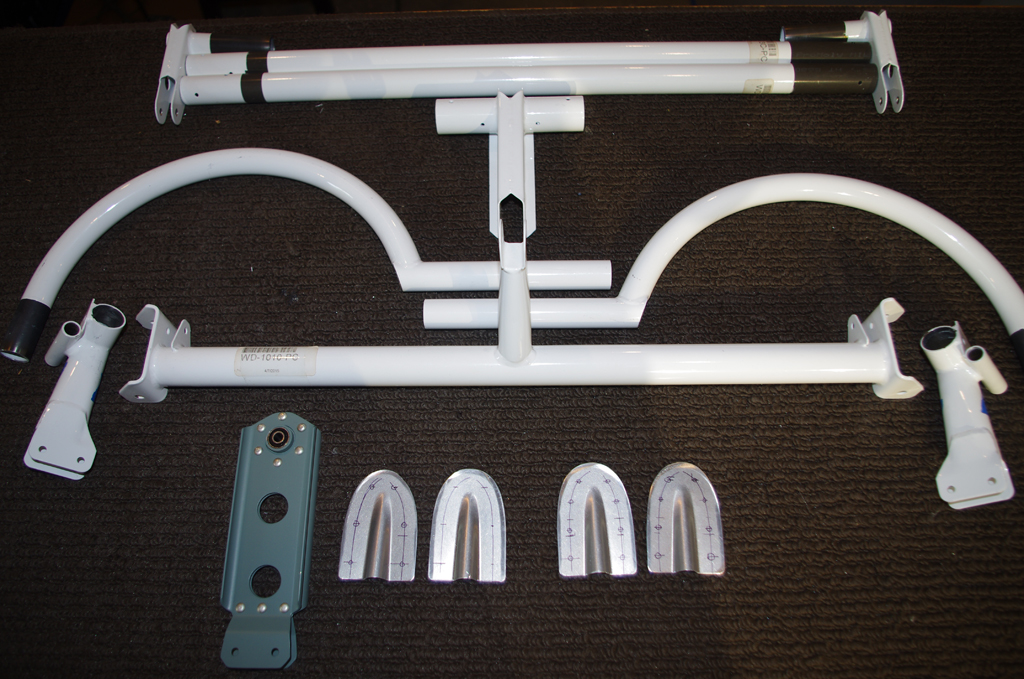
 These are photos of the control and flap system parts before fitting, drilling and deburring. The right picture shows the aileron pushrods which link to the control stick bases.
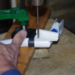
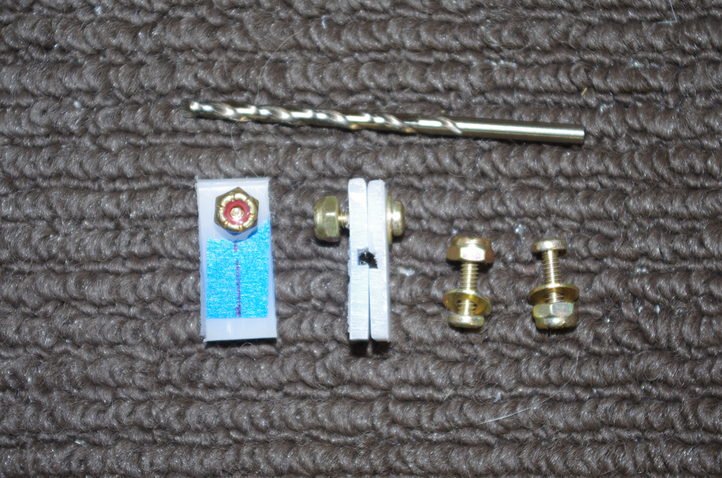
 The control stick bases were reamed for roundness after drilling the control stick itself, then were protected with tape and expandable ear plugs prior to priming the ends. The brass bushings were then driven into the pivot holes for a snug fit.
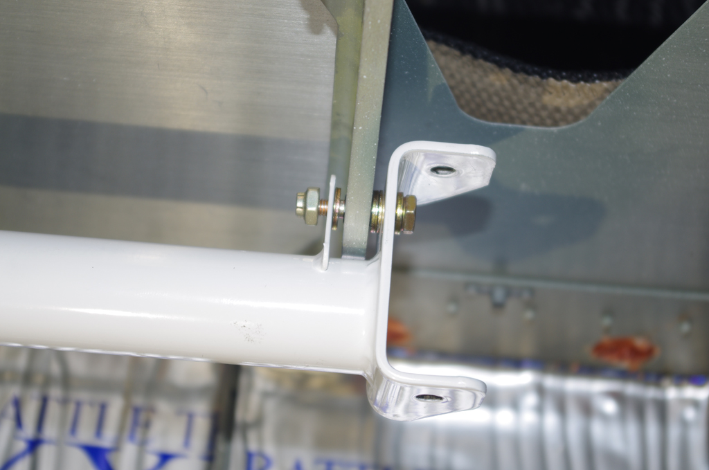
 The control column was installed with finger tight stop nuts, then the control stick bases and pushrod assembly were also loosely attached. After adjusting the length of the pushrod assembly to ensure the control sticks were parallel, all fixtures were tightened and Torque Seal applied.

 Though officially part of the rudder controls, the plastic rudder cable guides were drilled. They were then attached to the forward tunnel.
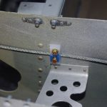
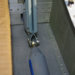 This shows the elevator idler arm in final configuration with pushrods attached. The space was tight for my hands when inserting the bolt, rod end bearing and washers. A rare earth magnet on the bolt end and washer pliers greatly helped during assembly.
 This jig was created to align the neutral position of the elevators at the bellcrank position. The final configuration was established with later posts on Empennage Attachment.

 Here are photos of the rudder pedal linkages and the rudder attachment.
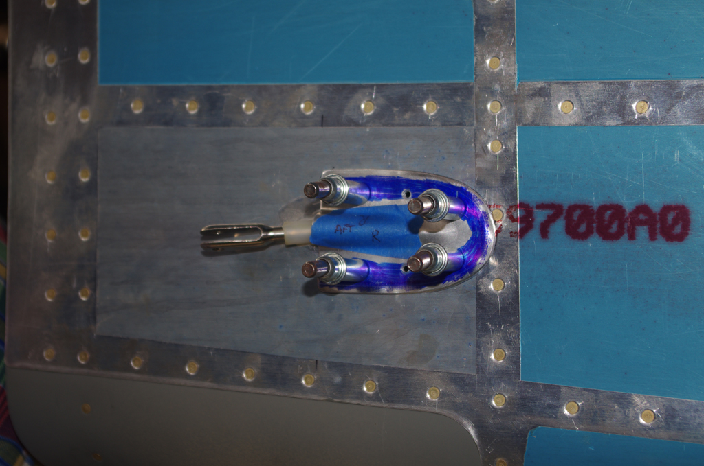
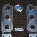
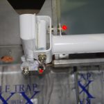
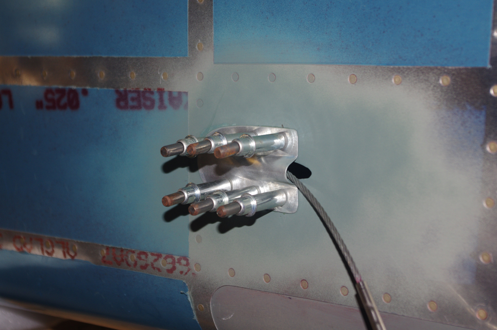 Fairings were added to the cables outlet locations for added strength and a touch of streamlining.
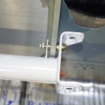
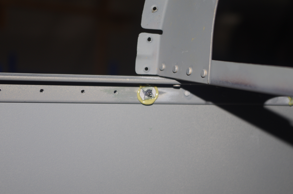 Experience from other builders indicate the holes tapped in the longeron for the #6 screws holding the empennage fairings will eventually strip out from taking on and off. While the tail section has not been completely sealed and the access was relatively easy, I added Click-Bond nutplates.