Eric helped match drill all the rudder skin holes common to the spar and stiffeners. I do not understand the instructions drilling the trailing edge. In one step the plans call for drilling perpendicular to the chord of the rudder, later it talks about countersinking holes perpendicular to the trailing edge surface. Right now these seem like contradictory instructions. I will need to get some clarification before proceeding.
Monthly Archives: December 2013
Rudder Skins
The rudder skins were prepped and rigged ready for match drilling (Sections 7.6.3 – 7.6.5)
 Today I used the soldering iron trick to cleanly peel away vinyl from the edges and rivet lines on the exterior side of the skins. There is a big debate in the community about the utility of leaving the vinyl on (scratch resistance vs. corrosion potential), but I think it looks cool. Besides the plane parts are currently stored in our climate controlled bonus room, plus I do not intend to spend decades waiting to process and corrosion treat these materials.
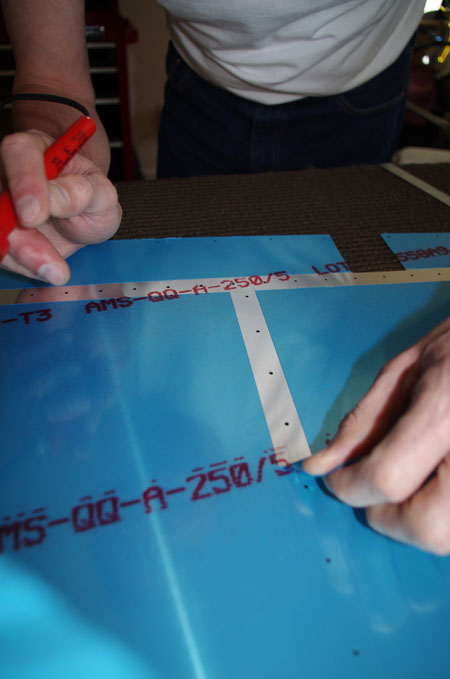 Removing the vinyl strips…
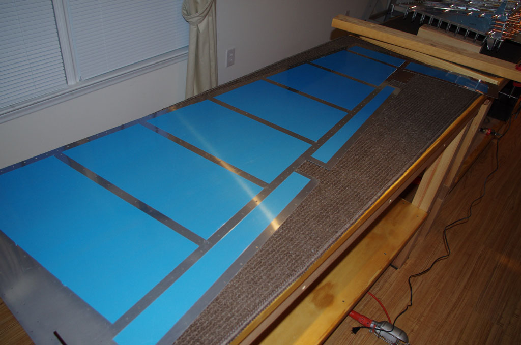 Final product.
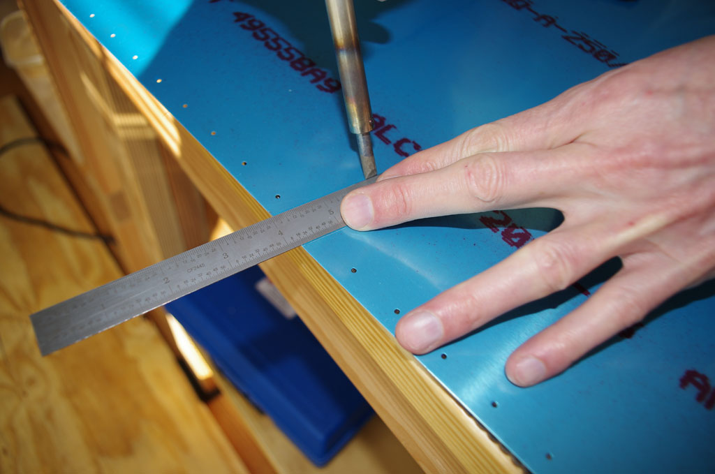
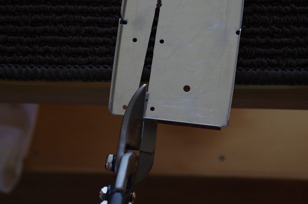
 Here the rudder trailing edge is being attached for final trimming to appropriate length.
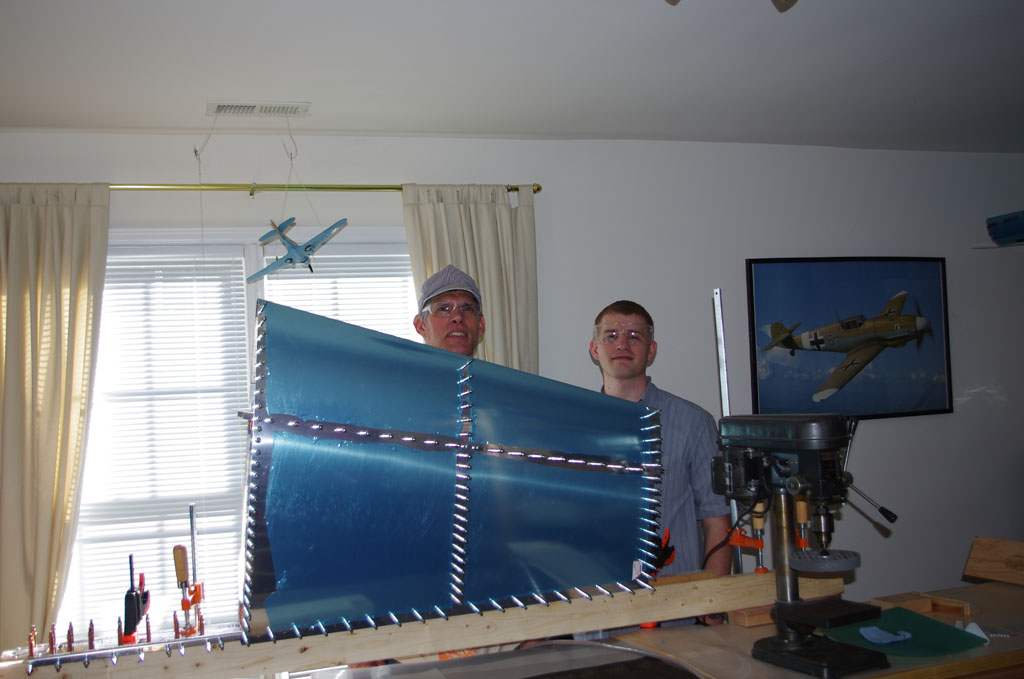
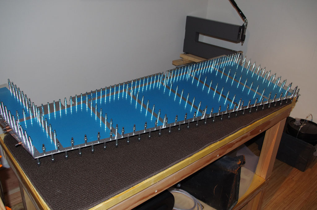 and the whole nine yards clecoed together ready for match drilling.
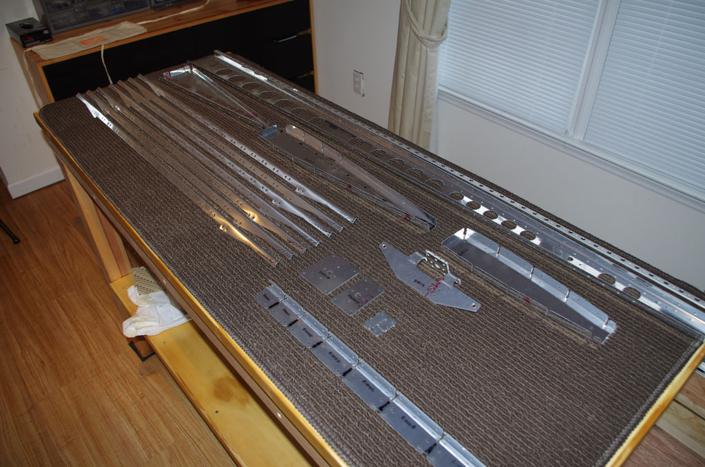
Rudder Framework
All the steps for 7.4 and 7.5 were completed today, along with 7.6.1 and 7.6.2. This means all the rudder framework parts (spar, horn, ribs, stiffeners) have been drilled, countersunk, and deburred ready for corrosion prep. It took about 5 hours to get this done.
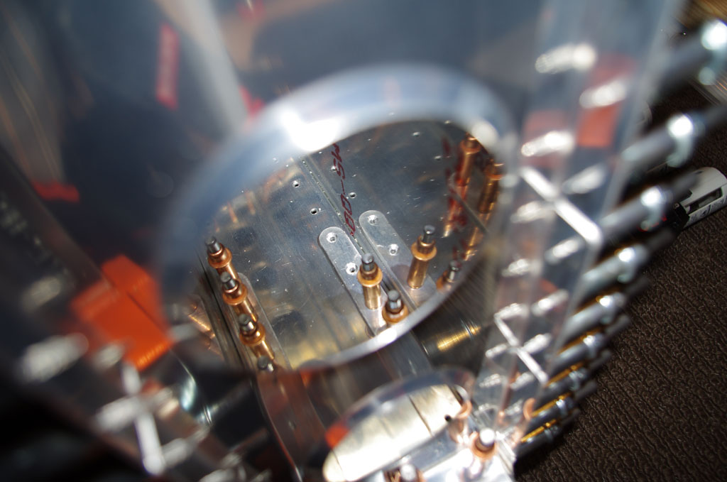
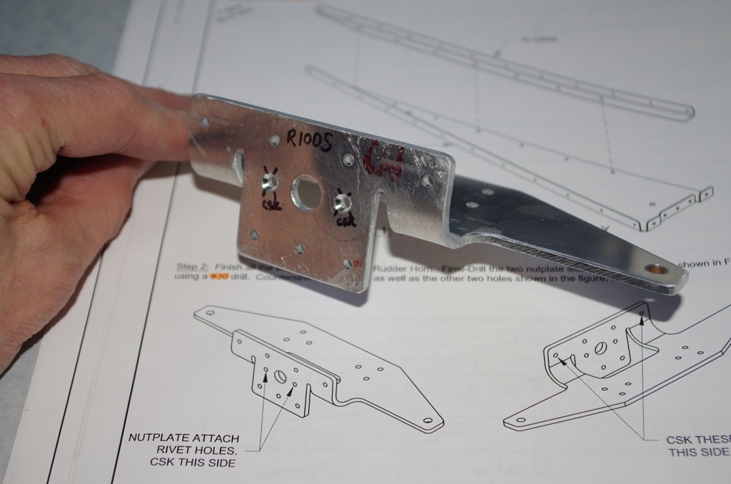 The first steps involved countersinking nut plate fastener holes on the Rudder Horn. This is a crucial part of the airplane steerage mechanism as the rudder control cables will attach here. Countersinking this side with a micro-stop countersink cage was easy, the backside not so.
 the back part of the horn piece is rounded, meaning the countersink cage cannot be aligned perpendicular to the surface and parallel to the hole. As a result, hand countersinking was required.
 Voila. Using a hand crank attached to the #30 countersink bit, I was able to get the proper alignment. It took a while longer to hand-bore out the metal, but actually I liked the control. The appropriate flush rivet was continually used to check the depth, which in my opinion turned out quite nice.
 Next was drill out the lower spar rib and corresponding flange part to match the attachment points to the horn.
 The striker plates were also countersunk by hand. These will eventually be flush riveted to the lower rudder spar. They serve as the contact points for the rudder stops prepared in Section 6 for the vertical stabilizer.
 Horn, striker plates, lower rib and spar clecoed together after match drilling and deburring.
 Stiffeners attached to the rudder spar.
 One rudder skin clecoed in place for stability. Next steps will be debur the other skin and peel vinyl strips off the exterior surface along the rivet lines.
Rudder Ribs
Finished separating the ribs parts with associated deburring from steps 7.2.1 and 7.2.2. Also ordered inital round of attachment hardware for the bonding straps and static wicks to be used on the vertical stabilizer and rudder.
MISC – Peter helped move the first dunk tank section out to the shed, plus added bracing to work surface legs. The premium buckets which will hold the alodine and brightener chemicals also came in yesterday. These were relocated out to the shed this afternoon.
VS Metalwork Complete
This week all the preparation metal work leading up to alodine processing has been completed. This means corrosion prep, priming, and final assembly with riveting remain, but at least all the fitting, match drilling, deburring, dimpling and countersinking operations are done. From the build plans Sections 6-1 through 6-4.5 have been signed off.
VS Skins
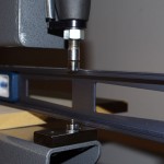
The first use of the DRDT-2 dimpling device was on the vertical stabilizer skins.

A spare tablesaw base with 2×4″ mounts was adjusted so the height of the C-frame bottom was level with the top of my EAA-1000 workbenches.
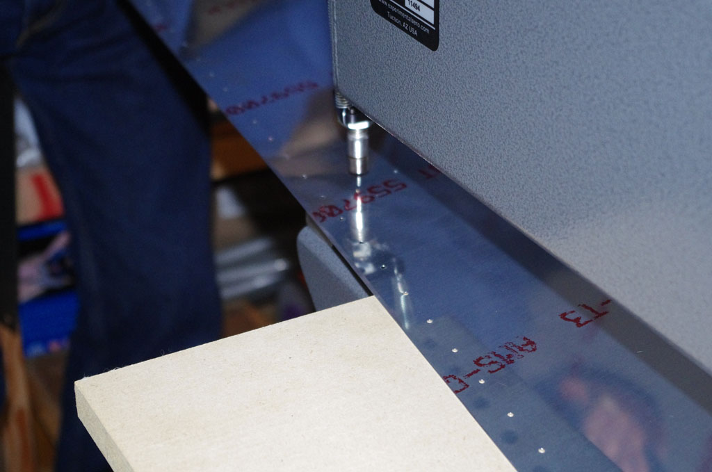
 Laying a 5/8inch sheet of MDF on the bench top provides a seamless surface to the DRDT-2. This picture shows the MDF will support the skin exactly level with the male die for the dimpling operation.

This setup allowed us to dimple with the skin resting on the bench top (saved me from building a special platform just for the DRDT-2 for this purpose). The process went quickly and the results were excellent. When properly setup, the DRDT-2 will produce a uniform dimple every time.
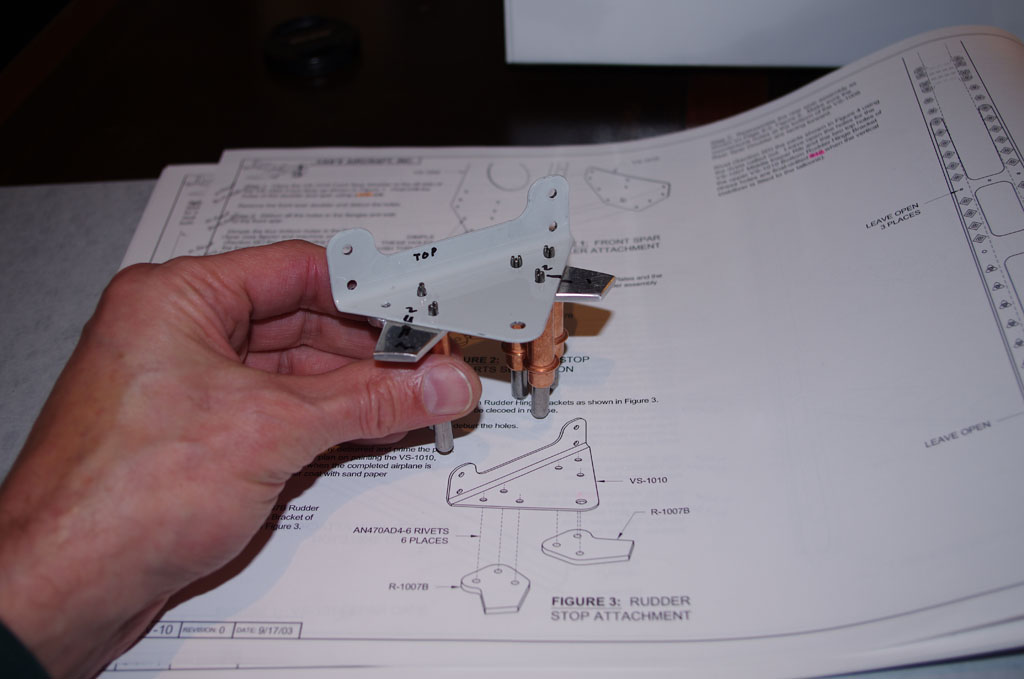
Repair Rudder Stops
In Section 6 the rudder stops are supposed to be fitted and match drilled against the upper of the bottom hinge brackets. I was about to post a picture of this activity when I noticed the lower bracket was showing in the picture. As a result, I went back today to correct back to the appropriate configuration (upper of the two brackets).
Rudder Start
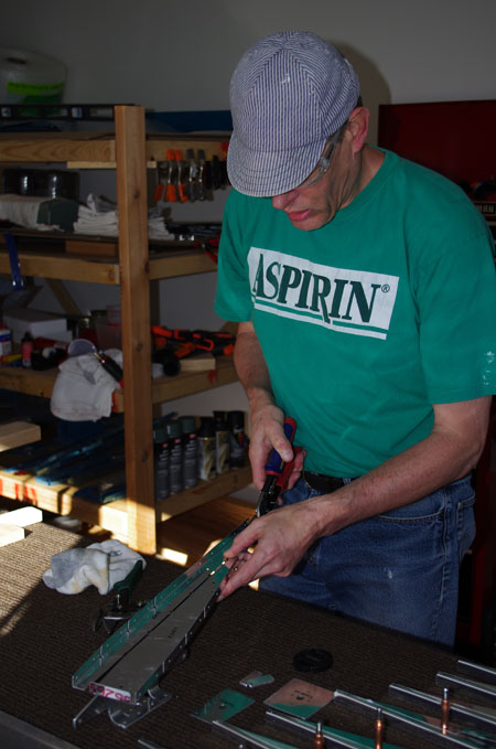
Started on the rudder section of the build plans today. The initial effort involved separating stiffener and rib pieces with tin snips after marking carefully. The usual deburring process then ensued.
Dunk Tank
The first section of the dunk tank for alodine and aluminum prep, DX503 and DX533 respectively, was completed today. It is make from three 8′ long 2×4 studs with a 1/4″ plywood bottom. This will be lined with 4-5mil plastic on each side, then filled with about 3 gallons of material. Drain holes at this end of the tanks will funnel material back into 5 gallon sealable buckets when each cycle is done.
The length of the tank is adjustable using 6″ 2×4 pieces. This 8′ section can be used for almost all empennage parts, the exceptions being the eleven foot spars for the horizontal stabilizer. For these another section about 5′ long will be made, then bolted to the end of this tank. Two smaller tanks in this configuration will be easier to manipulate than on huge 12′ tank. The backs of both tanks can also serve as painting surfaces when they are not in use otherwise.

Shed Improvements
This week Eric and I installed a work surface in the 8’x10′ shed in our back yard. The intention is to utilize the shed for corrosion protection and priming/painting. I have decided to use the alodine process (PPG DX503 surface treatment) on ribs and spars, using a dunk tank to submerge the parts completely for 100% coverage on all the nooks/crannies of these parts. The big flat surfaces like skins will be treated with PreKote.
After the different corrosion treatments, the interior parts will then be primed with two-part epoxy primer. The selected primer is PPG DP40LG, grey-green in color with good adhesion characteristics and excellent water vapor penetration protection.