All the steps for 7.4 and 7.5 were completed today, along with 7.6.1 and 7.6.2. This means all the rudder framework parts (spar, horn, ribs, stiffeners) have been drilled, countersunk, and deburred ready for corrosion prep. It took about 5 hours to get this done.
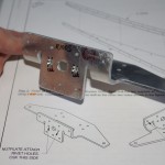 The first steps involved countersinking nut plate fastener holes on the Rudder Horn. This is a crucial part of the airplane steerage mechanism as the rudder control cables will attach here. Countersinking this side with a micro-stop countersink cage was easy, the backside not so.
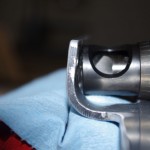 the back part of the horn piece is rounded, meaning the countersink cage cannot be aligned perpendicular to the surface and parallel to the hole. As a result, hand countersinking was required.
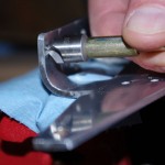 Voila. Using a hand crank attached to the #30 countersink bit, I was able to get the proper alignment. It took a while longer to hand-bore out the metal, but actually I liked the control. The appropriate flush rivet was continually used to check the depth, which in my opinion turned out quite nice.
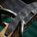 Next was drill out the lower spar rib and corresponding flange part to match the attachment points to the horn.
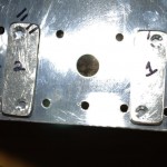 The striker plates were also countersunk by hand. These will eventually be flush riveted to the lower rudder spar. They serve as the contact points for the rudder stops prepared in Section 6 for the vertical stabilizer.
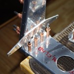 Horn, striker plates, lower rib and spar clecoed together after match drilling and deburring.
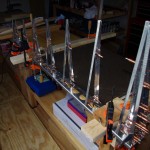 Stiffeners attached to the rudder spar.
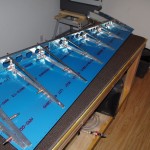 One rudder skin clecoed in place for stability. Next steps will be debur the other skin and peel vinyl strips off the exterior surface along the rivet lines.