Monthly Archives: March 2014

You are browsing the site archives by month.

Rudder Assembly – Part 1

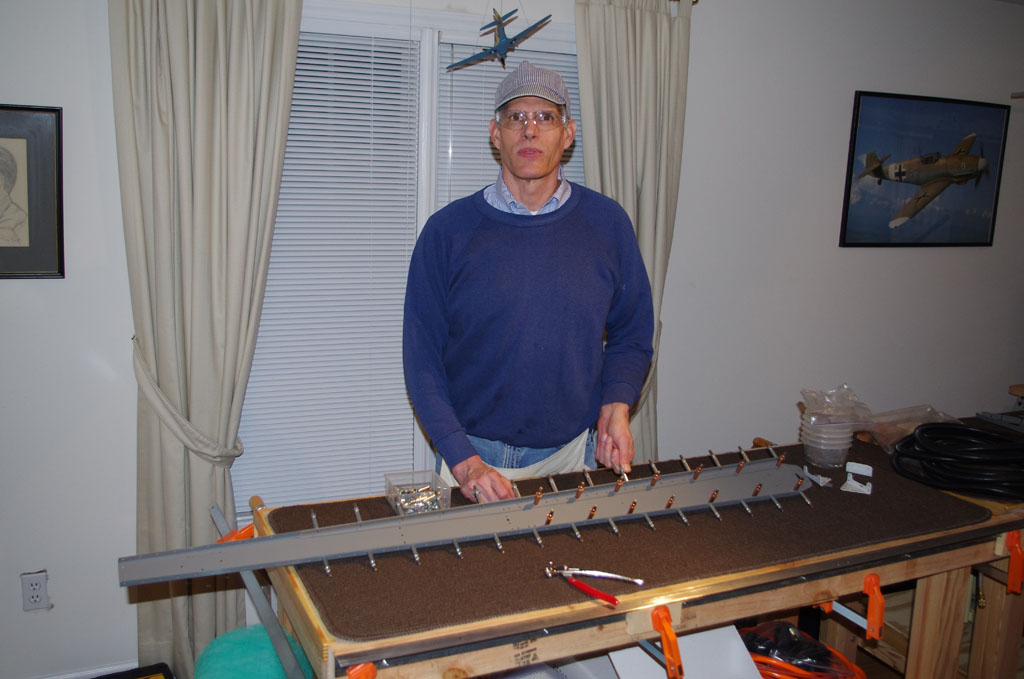
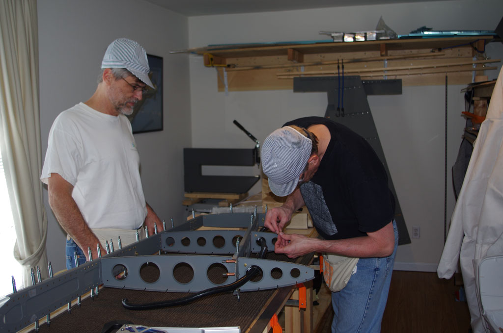
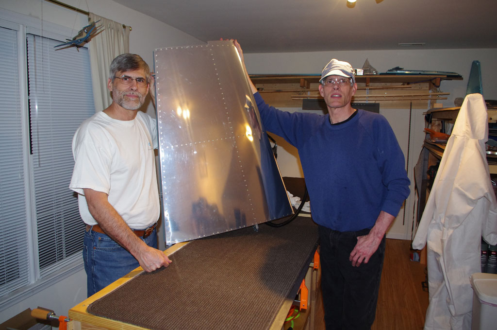
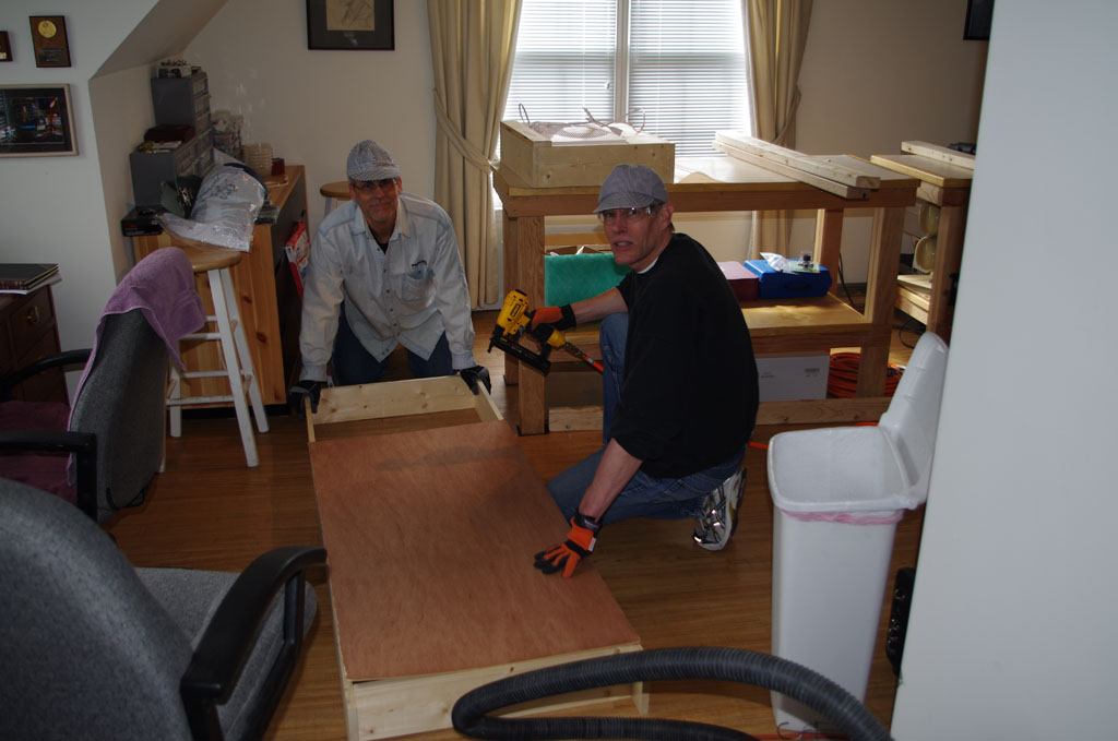
After a week in LA on a business trip and another week in bed sick, I finally got back to plane activities.  Over the weekend Eric helped me with the initial rudder assembly, the primary focus is to bond and jig the trailing edge.
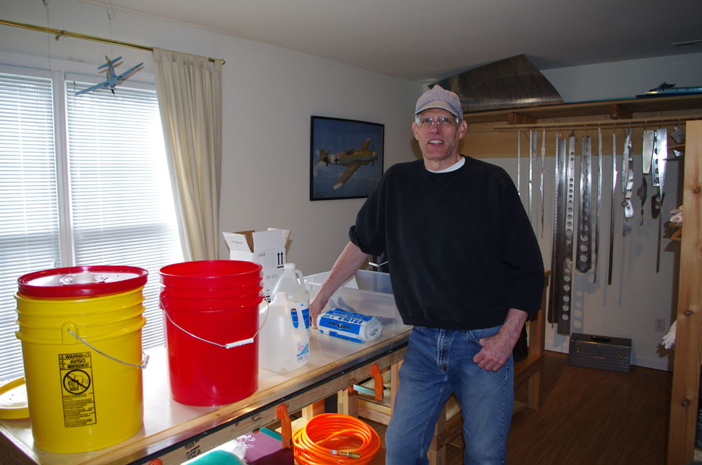
IMGP4028Getting ready.


IMGP4031
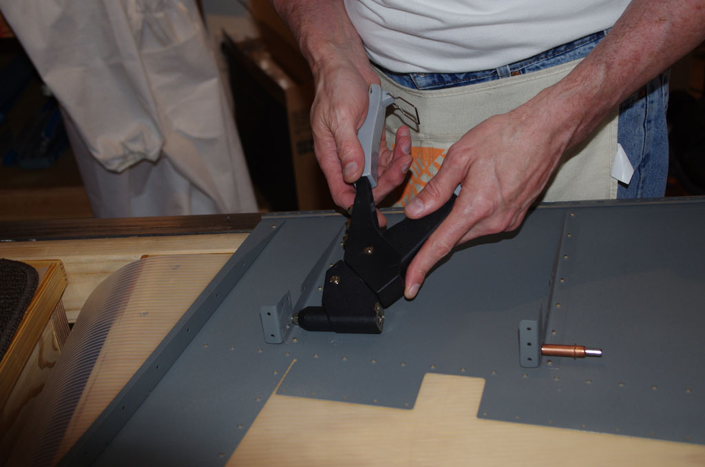
My first use of the pop rivet gun was attaching a retaining clip to the stiffener brackets. Here on the top stiffener. Notice how low the clearance is between the right skin and the width of the clip.


IMGP4035
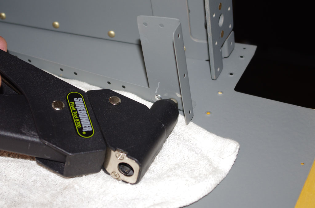
Here on the lowest stiffener.


IMGP4039
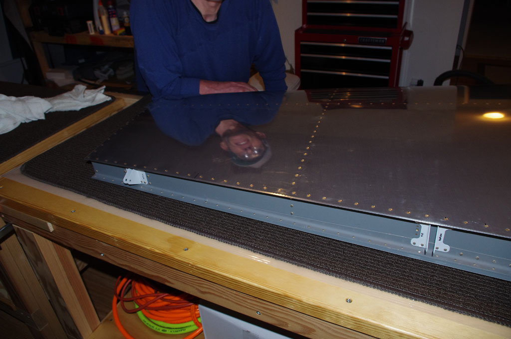
We used Van’s equivalent of ProSeal to bond the AEX trailing edge strip to the skins.  Here we are smoothing the globs with popsicle sticks. The instructions say you have about two hours to work with the material before it gets hard.  We found it extremely tacky right out of the tube – almost the consistency of Play-Do.  BTW – this stuff really stinks (contains sulfide/sulfate components), so good ventilation is a must.


IMGP4045
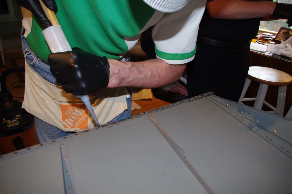
The Van’s stuff comes in a tube.  What they don’t tell you is a holder (like a silicone tube gun) makes the end use a whole lot easier.  I improvised with a piece of spare wood and hand power.


IMGP4047The instructions call for peeling back the left skin and pop rivet the stiffeners one by one.  The lower ones were fairly easy.


IMGP4048Pop riveting became increasingly more difficult as the spacing between skins got tighter and tighter.


IMGP4049See… 

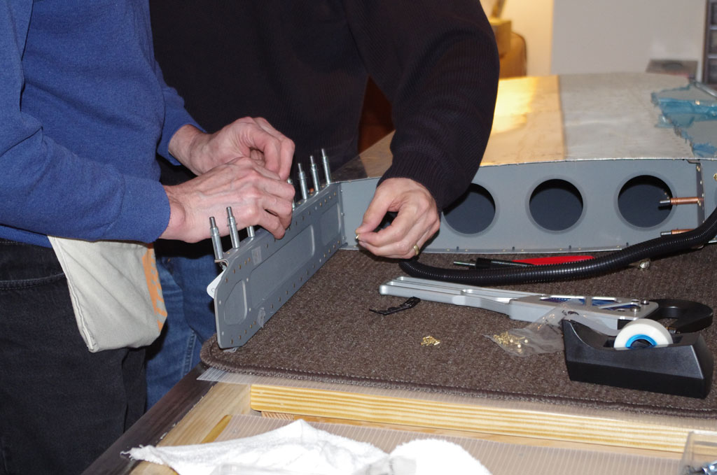
The left stiffener has to be placed above the right, but below the retaining clip.  Then the forward hole on left/right stiffeners gets pop riveted.  After setting all the stiffeners and the trailing edge, you cycle back to pop rivet  the retaining clips.


IMGP4055
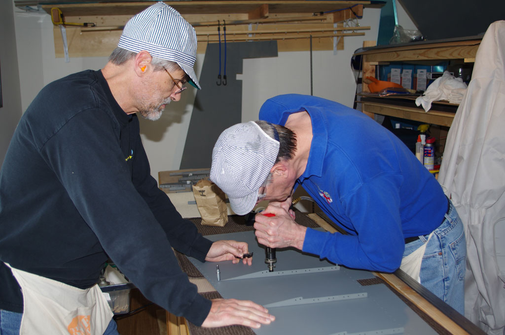
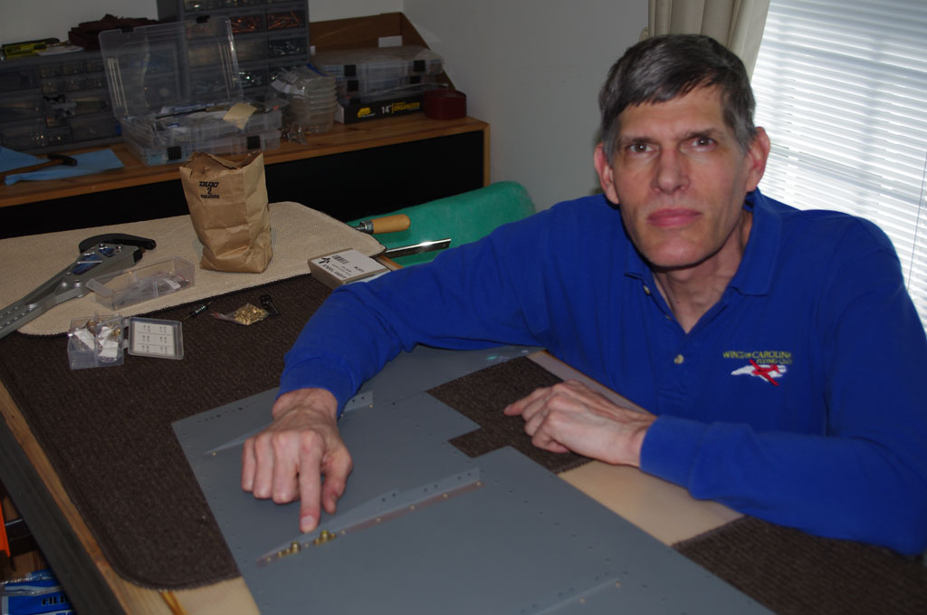
My big old hands are good for some things, but not others.  As the space between skins got smaller, I started using needle-nosed pliers to insert the pop rivets in the forward stiffener holes. This picture shows the gun aligned with a rivet before pulling.


IMGP4060
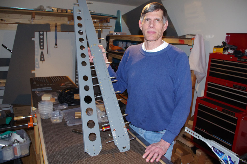
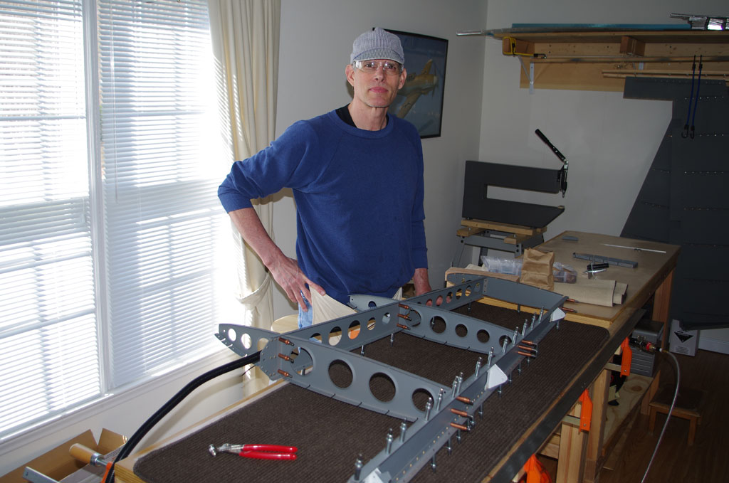
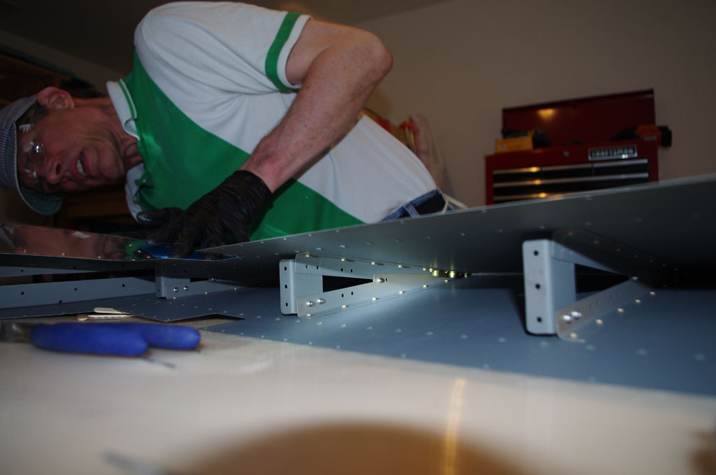
All the stiffeners have been placed, now aligning the upper ribs. Notice the over/under configuration of the stiffeners to the clips.


IMGP4061
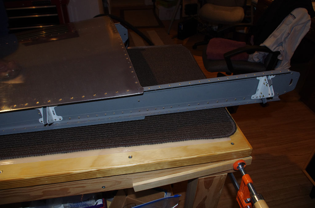
The trailing edge is clecoed down to my special angle bracket jig.  Wooden cloths pins and clamps hold the skins between clecoes.  Now a few days wait for the glue to cure is required before further processing.

VS Assembly

Another power weekend with Rich and the vertical stabilizer is assembled! After months of metal preparation, logistics and practice on sacrificial mini-projects, the big day for actually setting rivets in plane parts was upon me.  In the lead up week, my technical counselor (Terry Gardner) came by to evaluate progress and provide final tips.  With a bit of trepidation and rivet gun in hand, it was time to pucker and pull the trigger…

IMGP3980

Thursday evening the VS spar was assembled.  The spar, spar caps, doublers, and rudder hinges were all squeezed. No worries here and the results were good.


IMGP3987

No drill outs or smileys on the final spar assemblies.


IMGP3989

Rich and I made extensive use of a Van’s mini-wing project to practice the rivet/bucking techniques needed for most of the work on skins.  Good thing too, because our initial efforts were miserable.  The greatest damage was done when the tungsten bucking bar slid off the rivet, pounding the h*** out of the skin from the inside.  Many adjustments to the air pressure at the rivet gun were also needed to get things into a calmer, but effective range.


IMGP3991

I took a day off work to take advantage of Rich’s final days on his visit from Texas. This picture shows the parts staged on Friday morning for both vertical stabilizer and the rudder. The plan was squeeze, back rivet, then buck as many parts in that order.  First priority was completing the VS over the weekend, nice to have the rudder done if possible.


IMGP3996

Back riveting the rudder skins.  This was obviously not part of the VS build, but I wanted to save bucking activities until last.


IMGP3998

Again no problem.  The back rivet results are all good.


IMGP3999

Here is the final assembly of the static wick nut plates.


IMGP4000

Staging the VS frame for squeezing.


IMGP4003

Notice the flexible conduit running through the forward rib lightning holes.  My custom rib doubler and the lightning hole wire ties for holding the conduit worked like a charm.


IMGP4007

Okay, here is where a serious case of nerves set in!  Our first ‘production’ bucking experience was on the middle nose ribs.  I had to reach a full arm length into the skin cavity to hold the 1.7lb tungsten bucking bar up against an AN426AD3-3.5 rivet.  Other builders have seriously disfigured the skins in this section; this being one of the most difficult assignments on the whole plane build right at the beginning.  At this point I was very anxious and the pucker-factor quite large.


IMGP4008

This picture is fuzzy, but does show the finished rivets on the middle nose ribs.  I had to go through some contortions, but eventually was able to see the rivet/bar with a flashlight during the bucking operation. Seeing the rivet shank and not being blind made all the difference.  Added to this, Rich did excellent work driving the rivets with a steady hand and consistent manner.  I was quite pleased with the resulting shop heads.


IMGP4012

Finishing up the lower spar and spar cap squeezes.  The overall assembly process went slower than expected, but we were very deliberable on purpose.


IMGP4026

Final result on the lower part of spar. We used a 1.5″ diameter mushroom rivet set with a rubber apron for the skins.  The rubber apron kept the rivet set from bouncing sideways and cushioned the impact to some degree.


IMGP4025

Final result on the upper part of spar.  We made sure to use rivet tape on every single flush rivet. This small, but important step keeps the head from crushing off all corrosion protection on the rivet set or die, but also prevents the skins from getting scratched.


IMGP4021Saturday evening saw happy campers and great results! In the end we only had to drill out 3 rivets. Interestingly enough all three of these were squeezed. No smileys or dents in the smooth skin surface are also testimony to careful planning and solid execution. Who would have thunk it given my previous concerns about bucking.

I could not have achieved this excellent outcome without Rich’s help.

First Contact

Another power weekend finally saw the first parts riveted together!

IMGP3927On Saturday Rich helped me apply PreKote to the skins with a light scuffing with grey Scotchbrite.  The process is simple – apply, scrub, rinse thoroughly, hang to dry.


IMGP3965The treated rudder skins are hanging from the dryer racks in the shed.  The were left overnight to dry with a space heater and a 1000watt floodlight on to combat the near freezing temperatures.  With all the devices running, the shed maintained a comfy 23 degree Celsius.


IMGP3967On Sunday after lunch I got suited up and ready to spray.  Each time the process of preparation gets a bit smoother.


IMGP3968Back in the bonus room with my first two parts to rivet in hand.  Because these were not part of the Van’s build plans, I started with my custom-made doubler for the upper VS rib. Note all the primed VS and rudder parts on the drying racks in the background.


IMGP3970First contact! but also brought first mistakes.  The first set of squeezed rivets went so well, I overzealously put a rivet in the lower right drilled hole.  The three in this row are supposed to attach to the forward VS spar.  Okay, so used the rivet removal tool for extraction.


IMGP3972Just to prove I can make more mistakes, here is a closeup of the final rib combination. Close examination shows the forward nut plate rivets are slightly bent inward.  I was using the Main Squeeze tool properly, but with driving bits too short.  This caused the C-yoke to contact the nut body at the end of the squeeze, forcing the small angle on the rivet.  By using taller driving bits on the second nut plate, I got full clearance on the nut body – thus no contact, no angle and a resulting smooth surface.


IMGP3971Had only the nut plate been slightly bent, I would have drilled out and replaced it.  However, the doubler was also impacted and further rework would probably have done more harm than good.  This is one of those occasions where the outcome is fully functional, but not esthetically perfect in the eyes of the builder.

Overall this was a great learning experience, and hopefully the beginning of a constantly improving build process.

Breaking Bad

This was a power weekend – alodine and priming my first set of plane parts with expert assistance from Rich.

IMGP3864Here we are finishing the air handling system for the shed.


IMGP3866Getting staged for mixing brightener – dilute phosphoric acid with brand name PPG DX533 (one part to three parts distilled water).


IMGP3873The actual mixing process occurred in the shed to keep any fumes or spills out of the house.


IMGP3887Here Rich and I are posing in front of the treated parts, first dunked in the brightener solution and rinsed with water.  The drying racks just hold the pieces before the alodine process, no real need to have them bone dry at this point.


IMGP3892One of the VS spars goes into the alodine solution in the dunk tank.  The first pieces in the fresh solution for 2 minutes turned very dark, so the immersion time was adjusted to get a more golden color. Everything was hung overnight with a space heater on for complete drying.  This is necessary before the priming steps.


IMGP3896Suited up and shaking the PPG DF40LF grey-green primer.  I only got a quart, which turned out to be way more than needed for this batch of parts.


IMGP3900Using a graduated measuring cup marked for 2:1 primer to catalyst.


IMGP3908Ready, aim, fire.


IMGP3914Rich took this picture through the shed window showing primer actually being applied to some parts.


IMGP3916Why the grin?