Tag Archives: Rv10

HS Part Mods

In addition to the start of deburring all the horizontal stabilizer parts, I have also begun marking those pieces to be trimmed or created from angle aluminum.
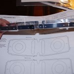
IMGP3775Two of the spar ribs require parts of the tabs to be removed.  Here the particular portions are noted with a Sharpie.
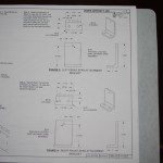


IMGP3790Manufacturing two attachment brackets from 2″ x 2.5″ angle aluminum is going to be a real challenge.  I do not have precision equipment to get the holes drilled to the tolerances laid out in the plans.  I will probably ask my technical counselor on some much needed advice before moving forward.
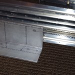


IMGP3781Here is my markup of the angle aluminum used for the attachment brackets.
Rudder Drilling – Part 2

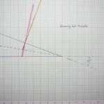
Used a chart and homemade guide to get the necessary 5 degree angle to drill perpendicular to the chord line as per instructions.

IMGP3685A rough drawing of the trailing edge configuration.


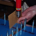
IMGP3687Home drill guide in operation.


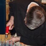
IMGP3688Drilling in progress.


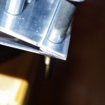
IMGP3689This close-up shows the trimmed trailing edge.  A bit more rounding is needed to smooth the AEX piece.  I intend using ProSeal (or equivalent) on the trailing edge, so hopefully some of the empty space will get filled with this material.

Rudder Drilling – Part 1a

The last few days I have been researching how to drill and countersink the rudder trailing edge.  By hand measuring the AEX aluminum strip I determined the acute angle to be about 10-to-12 degrees.  If the common drilled hole through both sides is perpendicular to the chord, this means the countersinking bit will be about 6 degrees off the drilled line when removing material to accept the skin dimples. This angular difference does not seem like much, but we shall see how it goes.

I have also spent quite some time finalizing the bonding strap and static wick configurations.  Using #10 screws, nut plates, and a 3/8″ braided copper mesh should do the trick for effective electrical connectivity.  My intention is utilize the open area near the middle hinge for the bonding strap.  Parts were ordered and have arrived from Aircraft Spruce.

MISC LOGISTICS – continue to acquire painting supplies and work on the configuration of the shed for alodine/prime processes.  I have my eye on a 7.2CFM, 2HP air compressor, but need our finances to stabilize a bit before pulling the trigger.

Rudder Drilling – Part 1

Eric helped match drill all the rudder skin holes common to the spar and stiffeners.  I do not understand the instructions drilling the trailing edge. In one step the plans call for drilling perpendicular to the chord of the rudder, later it talks about countersinking holes perpendicular to the trailing edge surface.  Right now these seem like contradictory instructions.  I will need to get some clarification before proceeding.

VS Metalwork Complete


This week all the preparation metal work leading up to alodine processing has been completed. This means corrosion prep, priming, and final assembly with riveting remain, but at least all the fitting, match drilling, deburring, dimpling and countersinking operations are done.  From the build plans Sections 6-1 through 6-4.5 have been signed off.

IMGP3528


IMGP3556

VS Skins

The first use of the DRDT-2 dimpling device was on the vertical stabilizer skins. 

IMGP3586

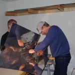
A spare tablesaw base with 2×4″  mounts was adjusted so the height of the C-frame bottom was level with the top of my EAA-1000 workbenches.


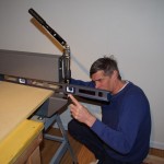
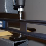
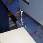
IMGP3583Laying  a 5/8inch sheet of MDF on the bench top provides a seamless surface to the DRDT-2.  This picture shows the MDF will support the skin exactly level with the male die for the dimpling operation. 


IMGP3595

This setup allowed us to dimple with the skin resting on the bench top (saved me from building a special platform just for the DRDT-2 for this purpose).  The process went quickly and the results were excellent. When properly setup, the DRDT-2 will produce a uniform dimple every time.


 IMGP3591