Bench testing the instrument panel required full connectivity of the ground and power wires, antenna connections and attachment of remote devices like the GSA28 autopilot servos. This is because the CANBUS wiring of the G3X system will not function properly without the right bus terminations.
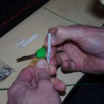
 Both the pitch and roll servos contain power and sensing wires. Standard DB9 connectors and shells were made up for each device.
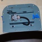
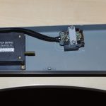 Custom brackets for the DSUB shells were designed using Blender, exported to .STL format, sliced, then 3D printed in nylon on a Prusa i3 MK3S printer. The resulting connections are very strong and should perform well in the plane. For the bench test they were provisionally connected straight to the instrument panel wiring (i.e. no breakout points or extensions).

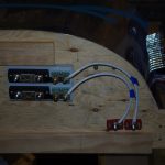
 AeroLED VX taxi, land and wig-wag light switches were tested on the bench. The picture at right shows the underside of the instrument panel wiring, especially where the grounding tabs and fuse block are located. While there are many wires in a small space, the organization seems good. At least now after familiarization with the wiring harness I can track down any wires with the help of an updated diagram.
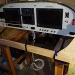 The test rig was powered through the ANL fuse / shunt holder connected to the firewall pass-through terminals. The amperage sensing wires are not shown in the left photo, but were used during the G3X configuration and test. On the right are the bench test setup. Note the control sticks are not yet configured here.
 This photo shows the first activation of the completed bench test setup! The control sticks are attached and almost all devices were powered up. Tests of all connected switches, avionics, and devices were successful. The GMU22 magnetometer and the GSU25 AHARS unit were displayed in the configuration page, but were not calibrated as specialized equipment is required. There were a few devices not configured at all for the test, such as flap motors, pitot heat and the CO detector. A complete set of tests will be performed later in the final installation. With the test setup the overall idle state electrical consumption was 7.2 Amps.
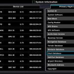
 These screen shots from the G3X Configuration Mode show the basic system information and detected devices. The test scope for this stage of the project was acceptable and the results were good. I feel much more comfortable with the avionics and electrical systems, so now on to more fuselage assemblies.