Electrical testing with the G3X system continued after installation of the Series 2, 24-pin CPC wing root connectors and other interior devices.
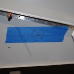
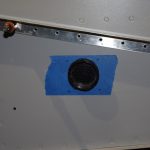 The position of the wing root connectors needed to have enough clearance to be under the wing root fairing, but high enough for easy accessibility in the side panel cavity. Careful measurements were taken before the side penetration was done.
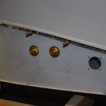
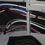 Additional holes in the left side were needed for the pitot and angle-of-attack (AOA) pneumatic tubes. The left photo shows a trial installation of the brass, right angle push-to-connect bulkhead fittings. The right photo shows the initially pulled configuration of the side wire bundles. In retrospect, I would probably rearrange how some of these wires are run.
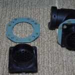
 A custom nut plate backer was fabricated for each CPC connector. This accessory will help fasten the connectors in the fuselage mid-shin. The right photo shows a right angle strain relief shell and the nut plate backer with the wing root wire bundled pulled through them ready for CPC male pin termination.
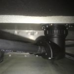
 The final CPC configuration – inside the mid-skin cavity and from outside the fuselage. The outcome was very good (more on the testing later).
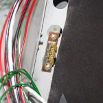
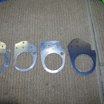 Custom ground block terminators were described in an earlier post. One of them was installed in the rear seat area for access from the wing roots and the aircraft rear conduits, which feed wires from the rear section under the baggage/seat floors to the forward compartment. The right photo shows a series of prototype brackets for the forward air vents.
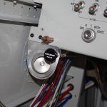
 The Park Brake push-pull cable will be located in the left side air vent bracket. Here a mock-up of the intended configuration is shown. While the vent is close to the brake lever, it does have a free range of motion and should have air flow impacted very much. The final painted and installed bracket is on the right.
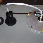
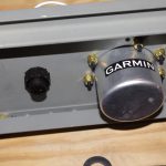 The previously free hanging Garmin GMU22 magnetometer cable was replaced with a custom rubber washer in 5/8″ hole drilled into the mounting bracket. This new setup now provides secure fastening of the connector to the transmission wiring.
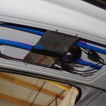
 Custom brackets were fabricated to mount the two Garmin GA26C and one GA35 antennas under the fiberglass canopy above the overhead console tunnel. The cover plate will be painted the same interior colors after the shoulder strap and headphone mounts have been attached. Note the GA26C antennas drive the Garmin G5 and PFD devices, while the GA35 provides WAAS-enabled signal for IFR flight with the certified GNC355 GPS/COM navigator.
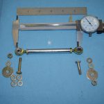
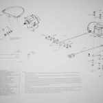 Mounting the Garmin GSA28 autopilot servos to the rear bellcrank mounts required configuration of the movement arms. The parts for the pitch servo are on the right. A diagram of the yaw servo parts are on the left.
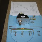
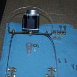 The yaw servo attaches to the rudder cables via a special yoke. This kit replaces the standard movement arm for the GSA28 servos.
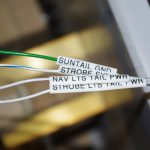
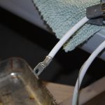 In general throughout the whole build every wire was labelled with the same indications as shown on the AS-BUILT drawing. The rear AeroLED Suntail wires were no exception. These were pulled along with NAV2, AUX/COM, and ELT antennas, and pitch trim wire through the rear conduits to the tail. The #2 Tefzel power and ground wires were then terminated with a 10 ton hydraulic crimper.
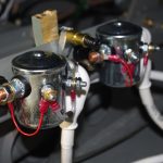
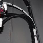 The terminated power wires connected to the PRI BATT and SEC BATT contactors. The final wires were cable laced with a rubber fuel line as protection against chaffing on the floor and J-channel stringers.
With internal wiring completed a complete range of power on tests were again performed. The CPC wiring, pitch/yaw servos and trims, battery contactors, flap motor, fuel pump, air vent, transponder, magnetometer, overhead lighting, GPS antennas and other components located within the core fuselage all passed initial functional testing. While the majority of electrical connectivity has been successfully tested, the remote wing devices and engine monitoring sensors remain.
MISCELLANEOUS
 Using leather punches I have started making custom washers from rubber or neoprene sheets of various thickness. Here are two 1/4″ thick rubber washers for the floor light mounts.