Further development of the interior included shaping the headliner backing and configuring the center console/armrest.
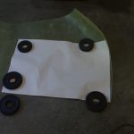
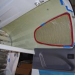 A tracing of the side window outline was laid against the fiberglass headliner template from Areosport Products. The fiberglass was rough shaped to the window contours, then finalized when test fitted into the canopy. Further actions include additional shape refinements and covering the fiberglass backer with grey headliner material. The lower side panels may also need relief to accommodate the thickness of the headliner at the longeron edge.

 On the left are #8 ClickBond nutplates being glued into place. Regular riveted nutplates could have been used here, but I wanted to avoid additional hole penetrations on structural elements whenever possible. On the right are holes cut into the forward center tunnel covers for heater cables and the AUX COMM connection.
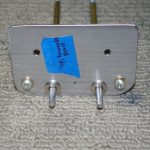
 A .060″ stainless backing plate was made for the heater push-pull cables. They require a D-shaped hole to keep the cable from rotating. Since I was not confident the carbon fiber side panels could withstand the stress without cracking, the approach to spread the forces across a larger area was taken.
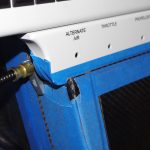
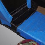 Here the Aerosport center console cover was rough fitted to the SteinAir control quadrant plate to the top and to the armrest base on the bottom. Particular attention was paid to where the fuel selector valve would be located. Notice the small lower seam between the center cover and the armrest base. This was achieved with a very slight tilt of the cover against the quadrant plate.
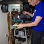
 Once the test fit of the quadrant plate was complete, the 3/4″ holes for the control cables were made with a Unibit in the drill press.

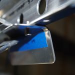 The throttle cable was checked in the quadrant plate before completing the remaining holes. The photo at right shows the mounting plate for the center console provisionally attached to the now permanently installed quadrant plate.
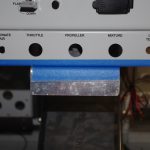
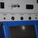 The mounting plate viewed from the front and with the center cover in place.
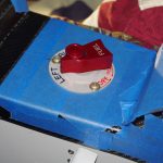
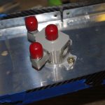 Next was drilling and fitting the Andair fuel valve selector in the lower armrest base. This was done very carefully and required about 6 hours to complete. The #10 screws shown in these photos are too high, interfering with the rotation of the selector. They must later be replaced with others with a lower head to allow freedom of movement.
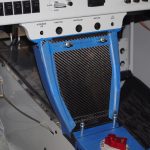
 Here are interim view of the armrest, center console, side covers, and lower instrument panel. Up next are fitting the control cables, layout and installation of headphone/microphone jacks in the center console, armrest adjustments and other final configurations above the tunnel.