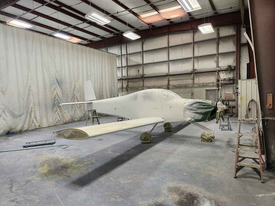
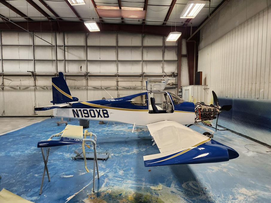
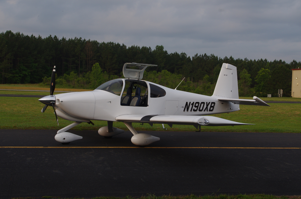
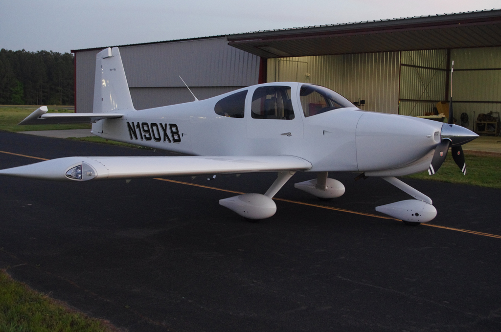
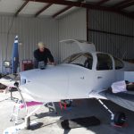
The final installations have begun after many years of component fabrication.

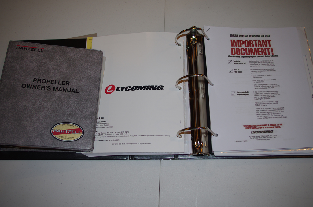
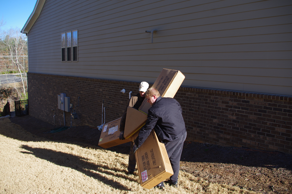
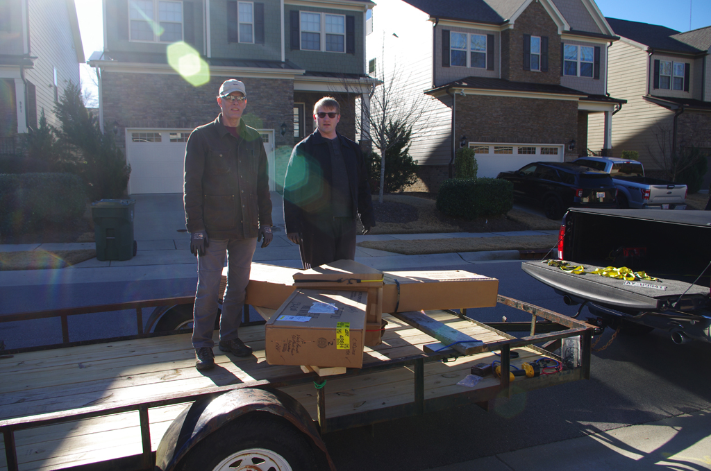
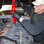
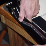
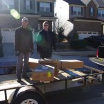 My son and I carried the propeller out of basement storage for transport to the airport.
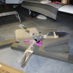
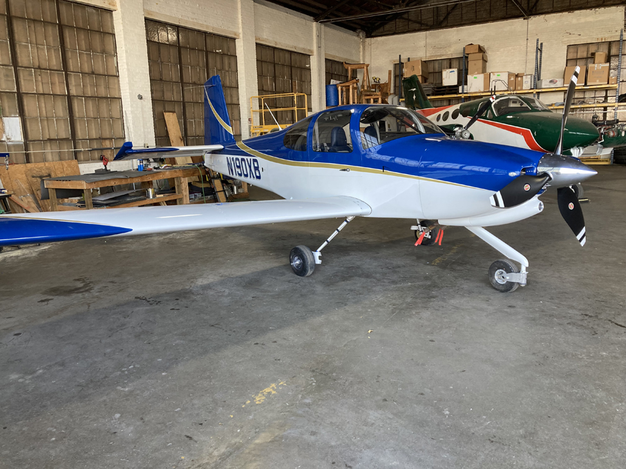
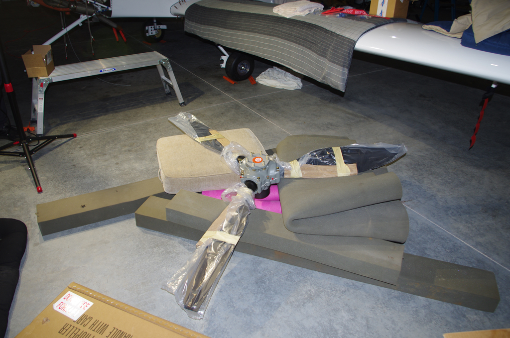
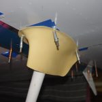
 The unwrapped propeller on the floor was checked, then hung by Terry, Eric and I. Sorry no photos were taken during that process. Needless to say, everything went well and the prop looks great. Easily the best looking thing about the aircraft!
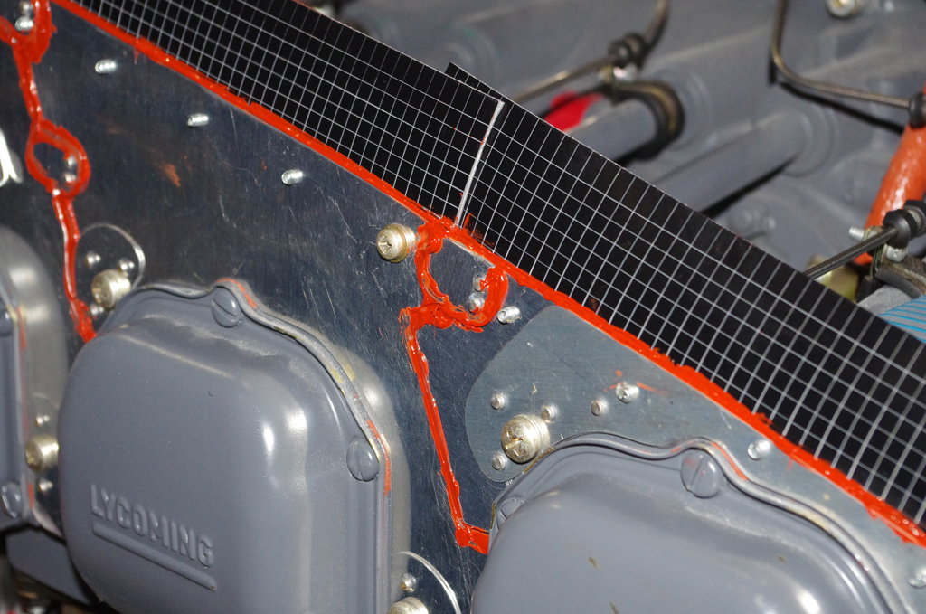
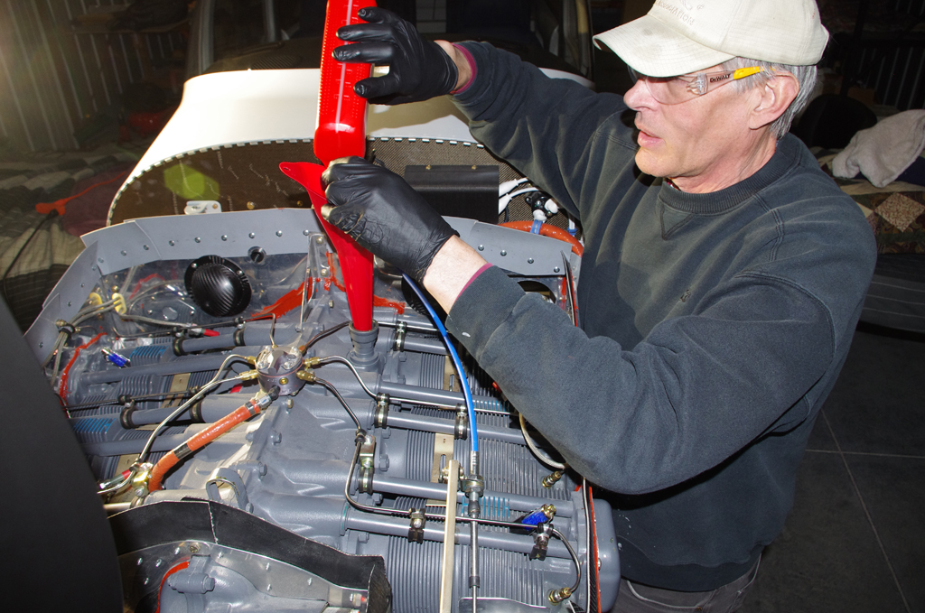
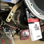
 High temperature RTV was applied to gaps in the baffling and between cylinder heads. The engine was then filled with 12qts of Aeroshell 100 mineral oil, which will be used for the 25-30hour engine break-in period.
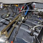
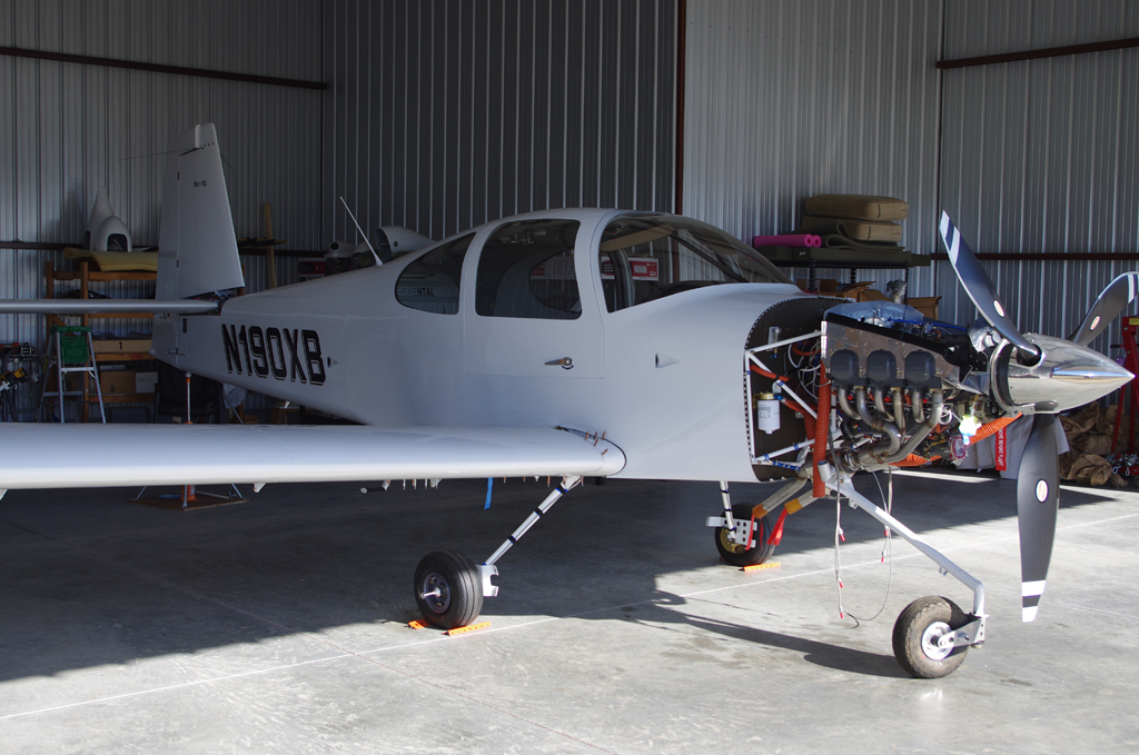
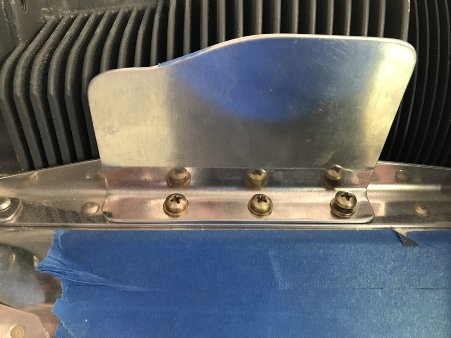
 Final connections of the propeller governor cable and bracket adjustments were made. The air dams with their original heights were installed. These were later reduced in size after some initial flight tests were performed.
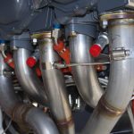
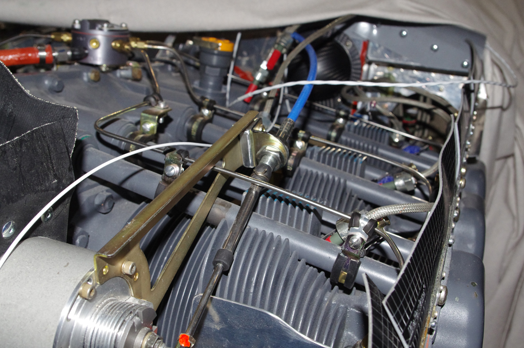
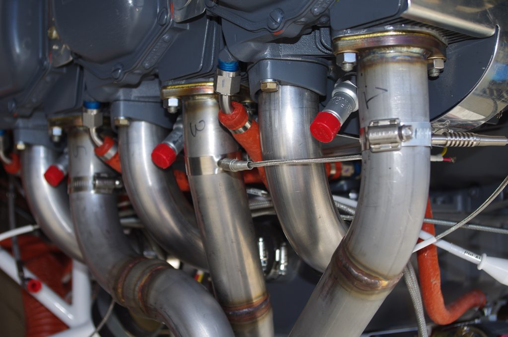
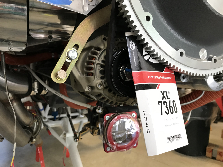
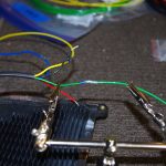
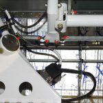
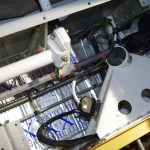
 EGT probes were installed in the exhaust manifold, then bundled with their corresponding CHT probe wires. The alternator belt was tensioned and Safe-T-Wired secure.
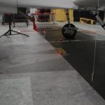
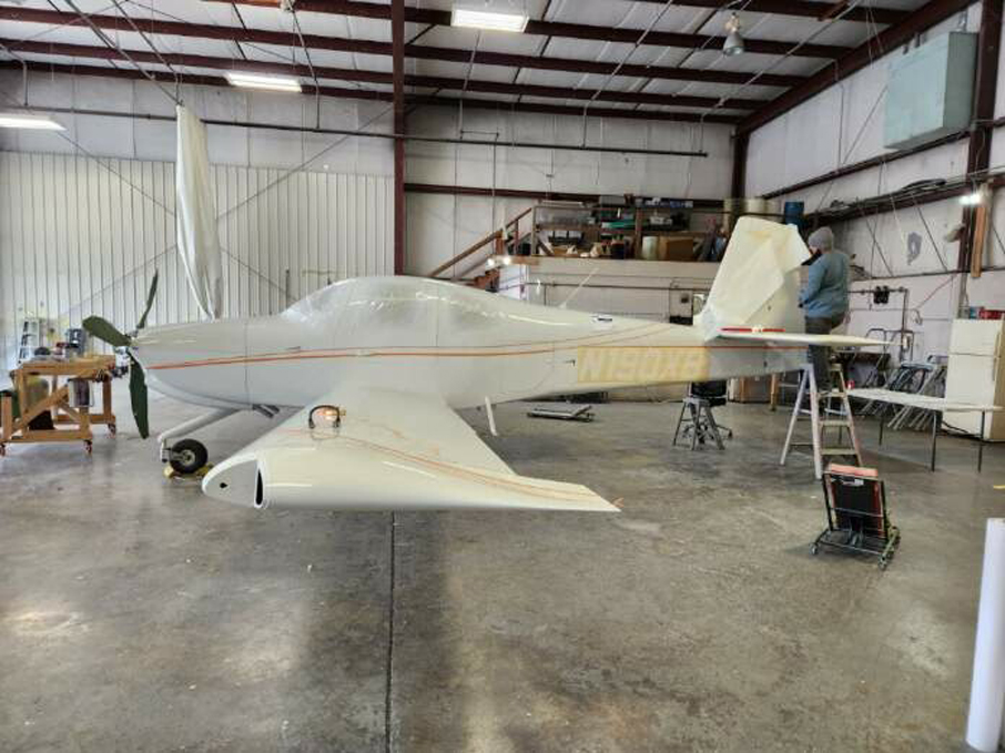
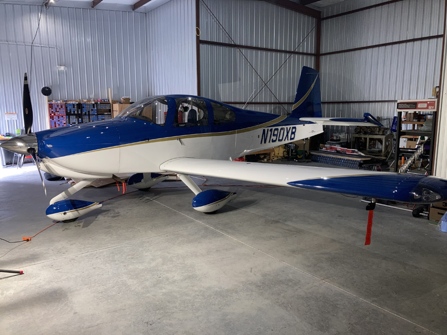
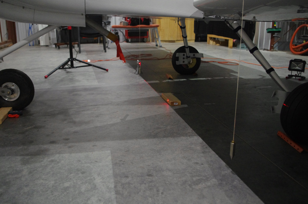
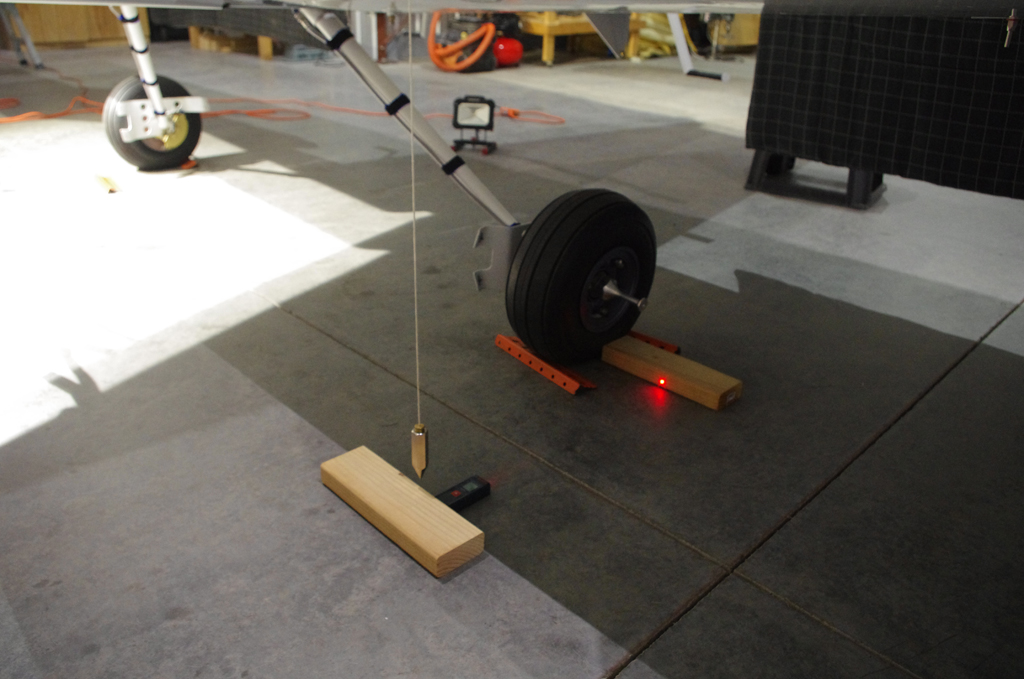
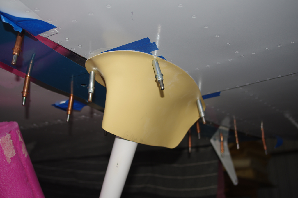
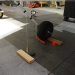 Measuring the leading edge of the wing provided a reference point for the CG calculations.
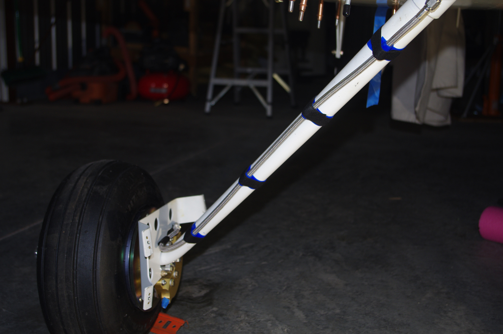
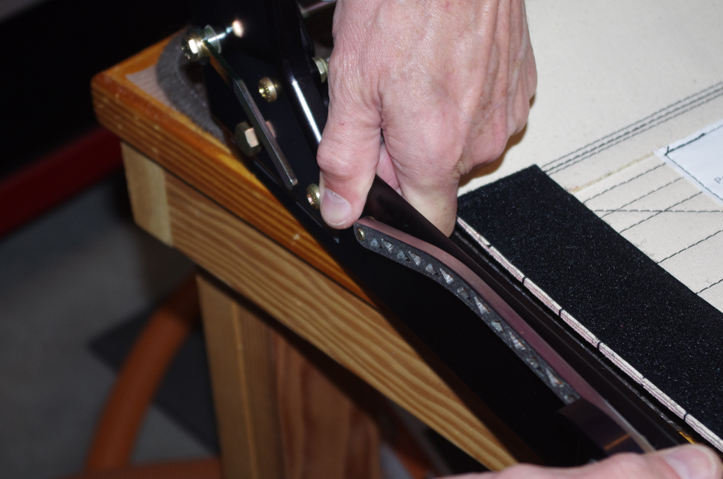
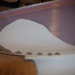
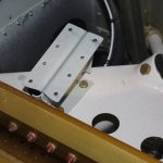
 Intersection fairings for the gear legs were initially fit, then later painted and installed after the TS Flightlines stainless braided brake lines.
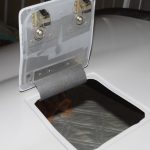
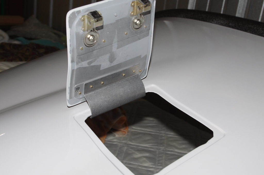
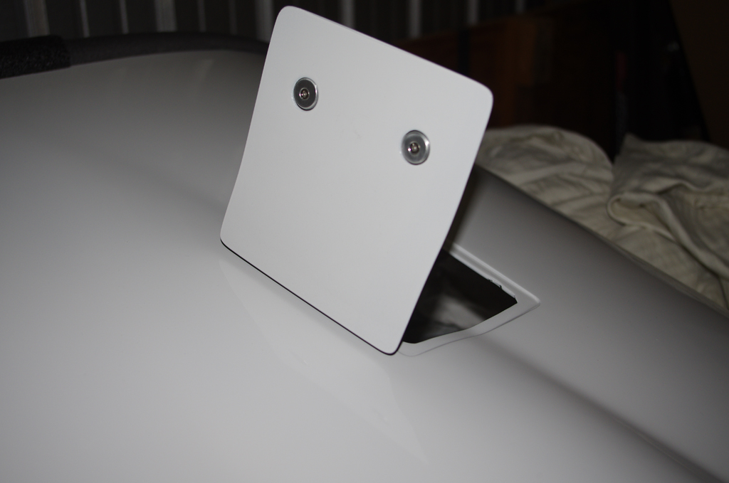
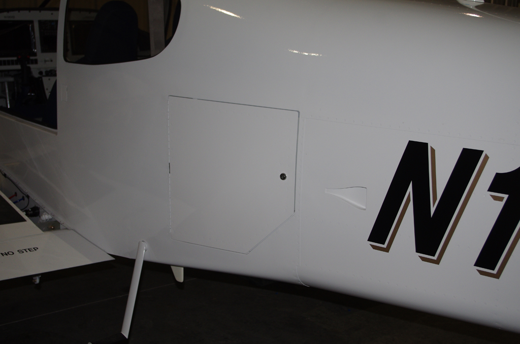
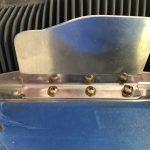
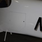
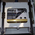
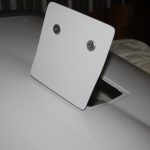 Final installation of the oil door with hidden hinge…
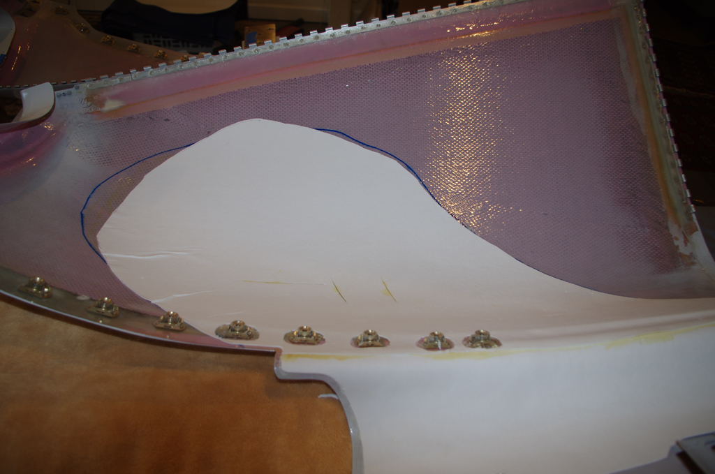
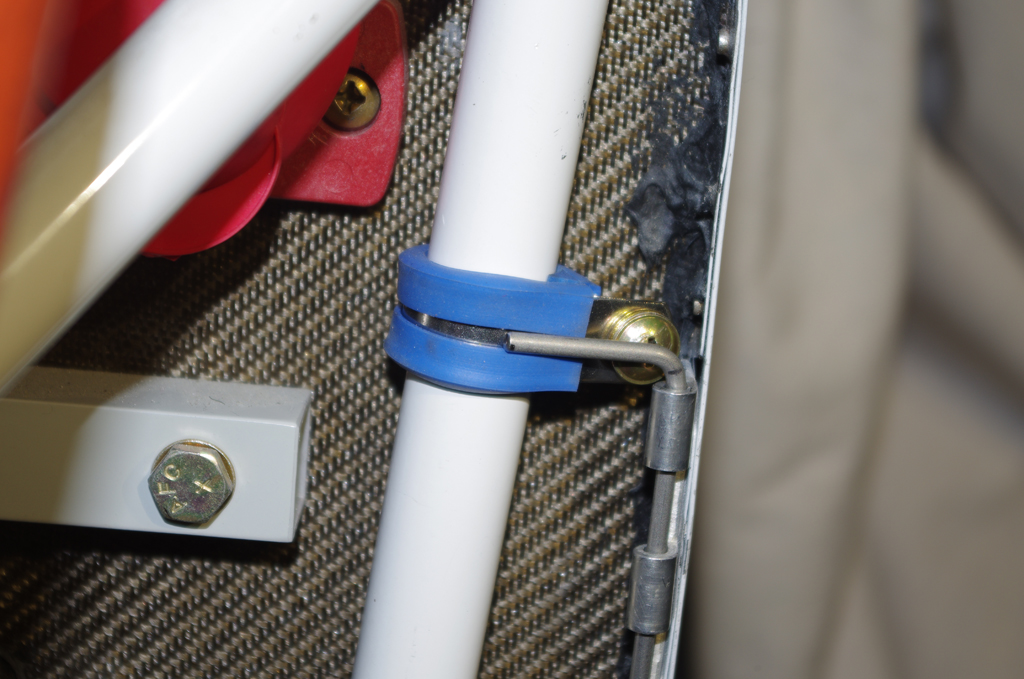
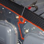
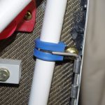 A 1/16″ ceramic mat was contact cemented in the lower cowl, then covered with Vans aluminum heat shielding. This combination should prevent the cowl paint from being scorched by the exhaust manifold heat. Lower cowl pins will be secured against these Adel clamps with tie wraps.
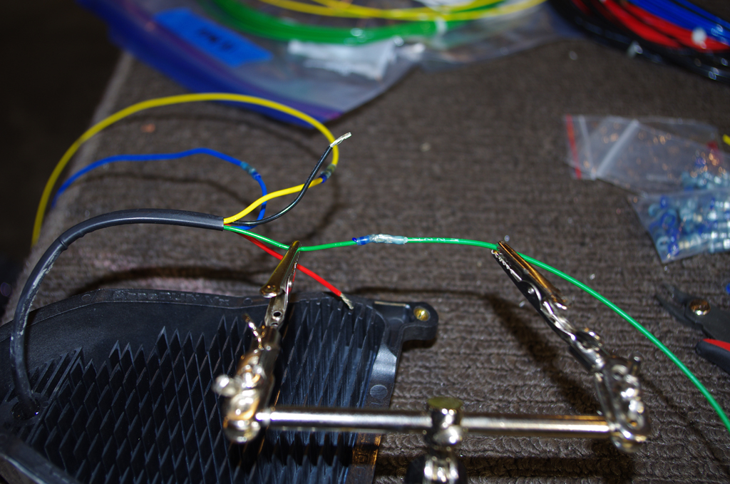
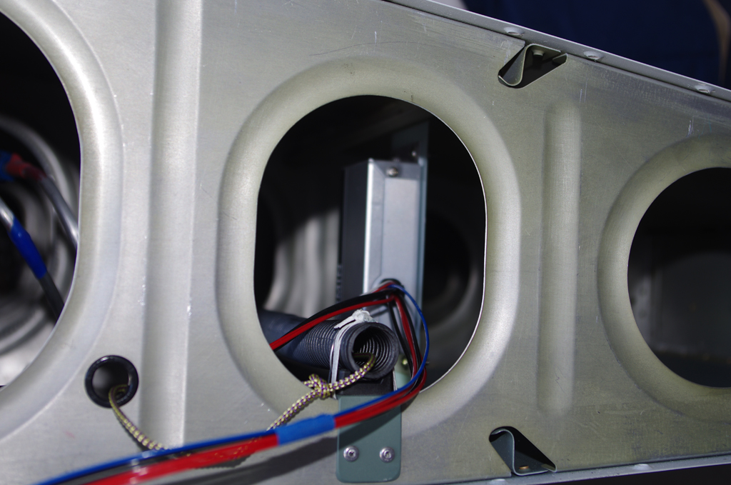
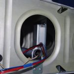 Final wiring for AeroLED VX landing lights were Solder Sealed, then run through conduit to the wingtips.
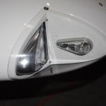
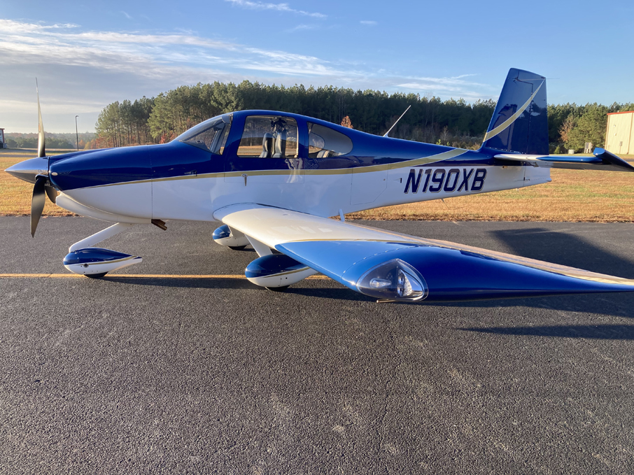
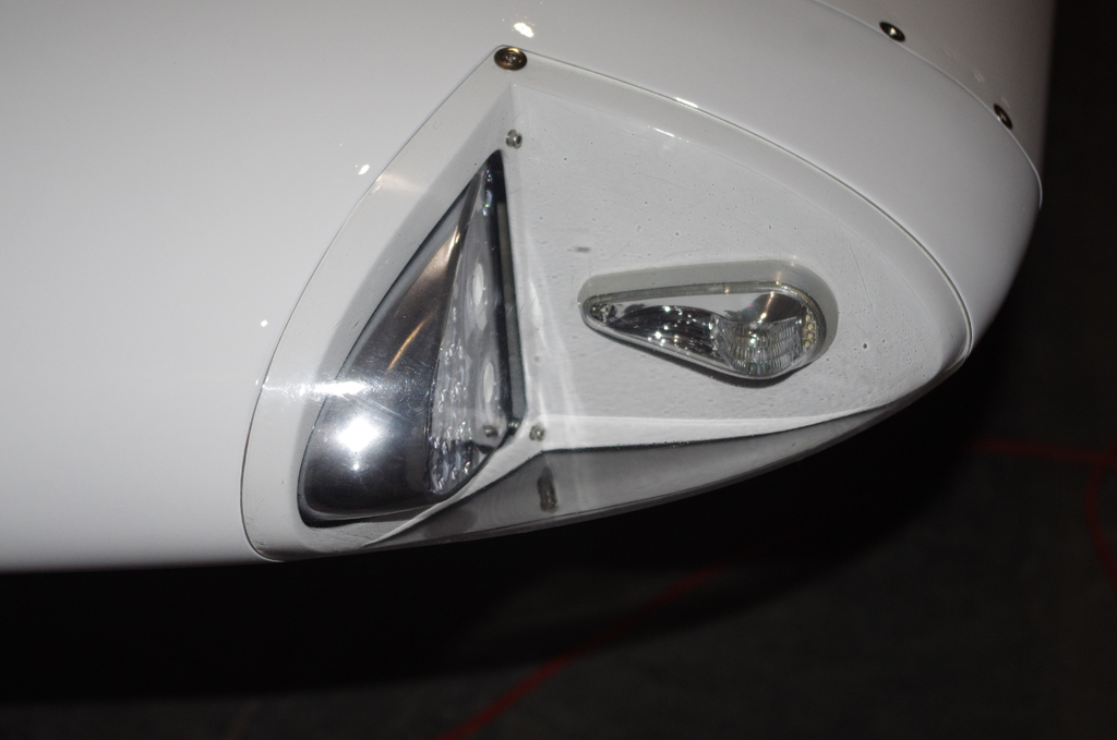
 AeroLED VX landing and NS position lights/strobes…
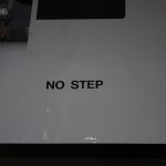
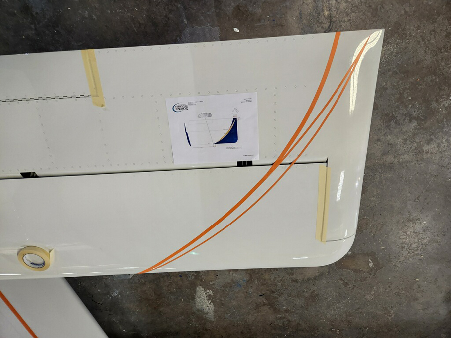
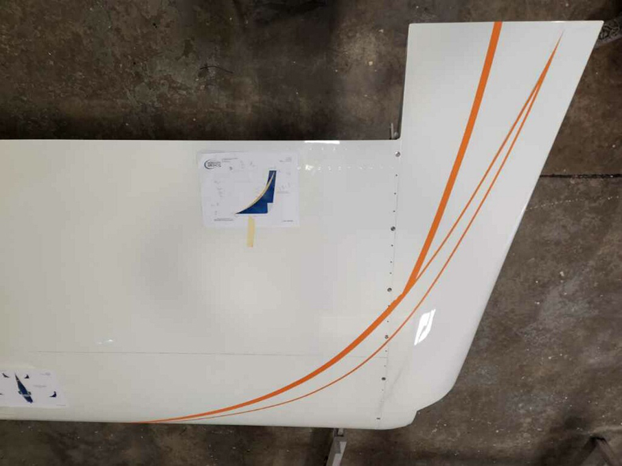
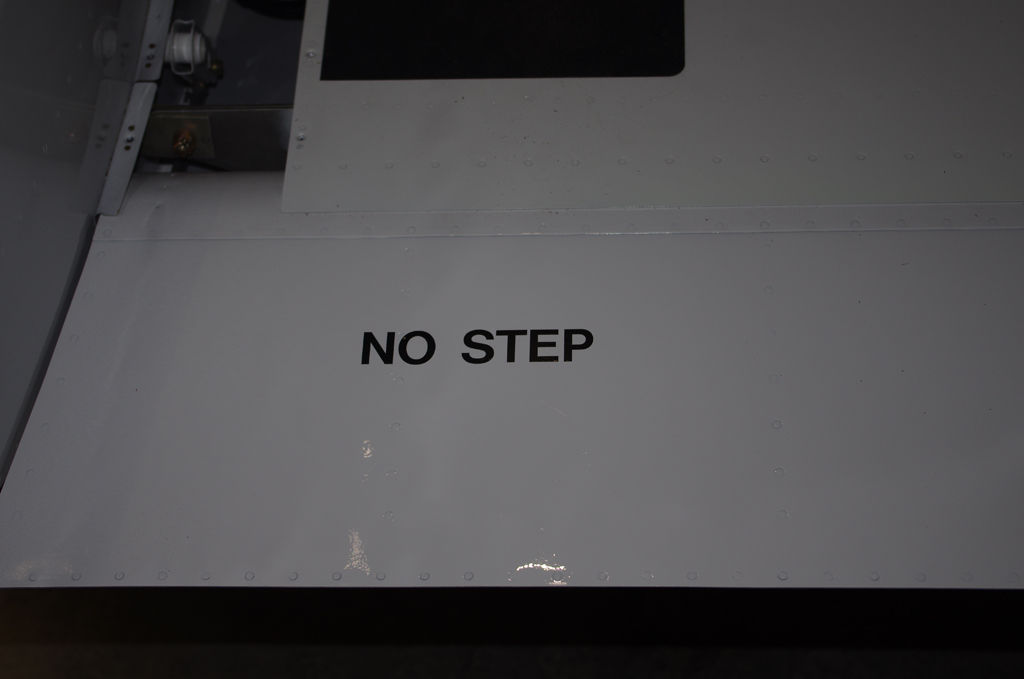
 Decals applied to flaps and doors…
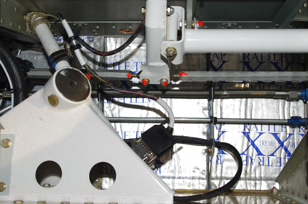
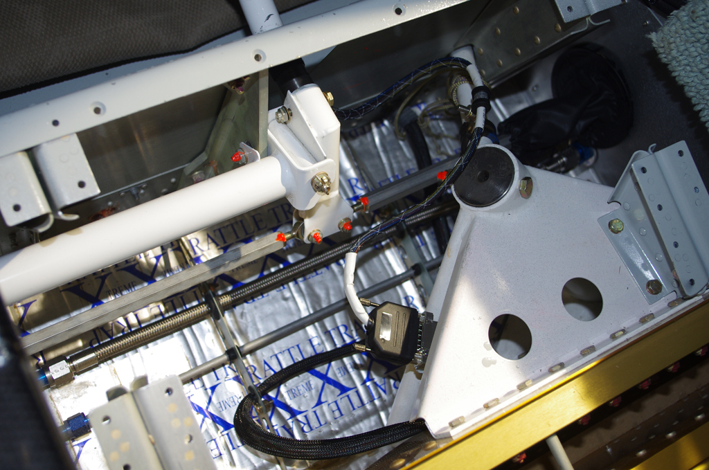
 Wiring from control sticks to system buses used DB15 connections for easy maintenance or removal.
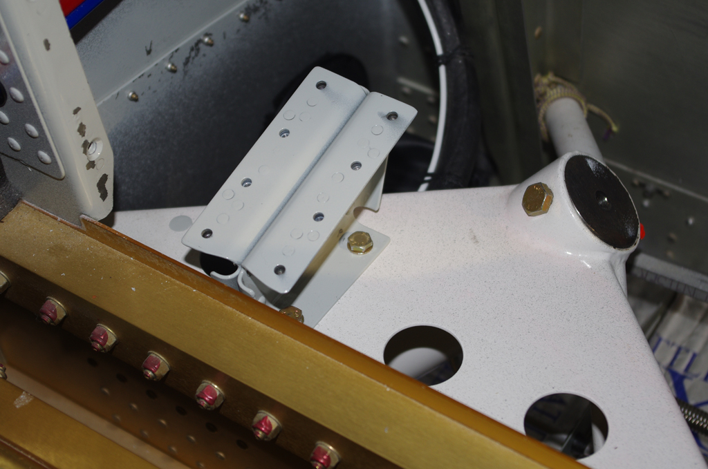
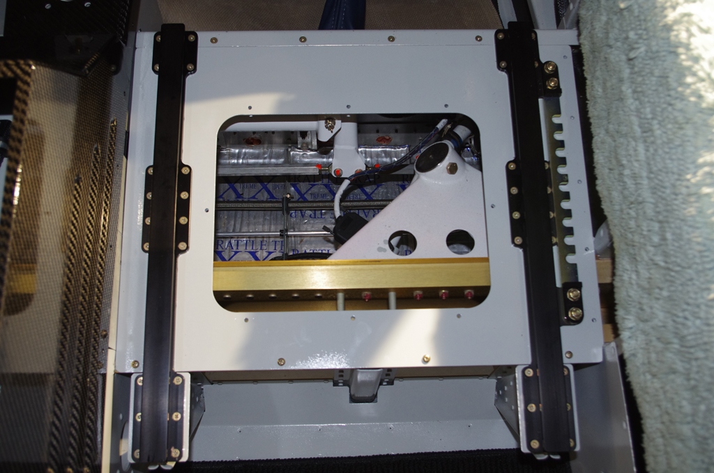
 Ground wires were covered in thick rubber fuel lines to prevent chaffing, then seat pans were installed.
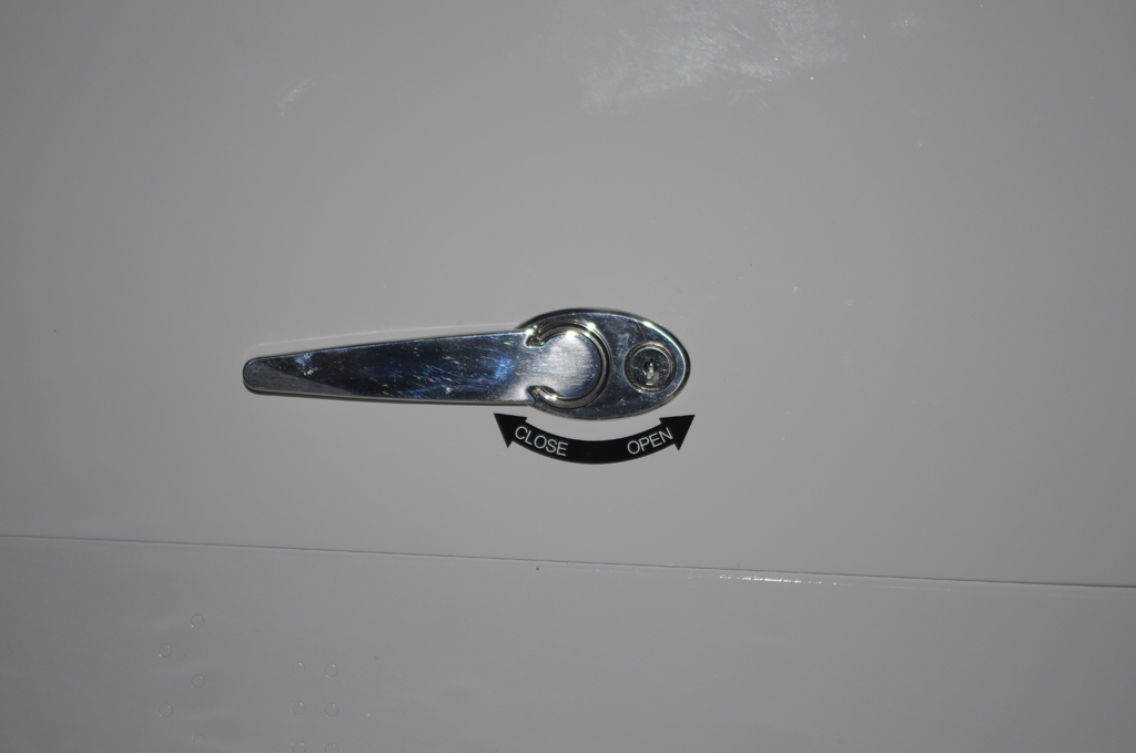
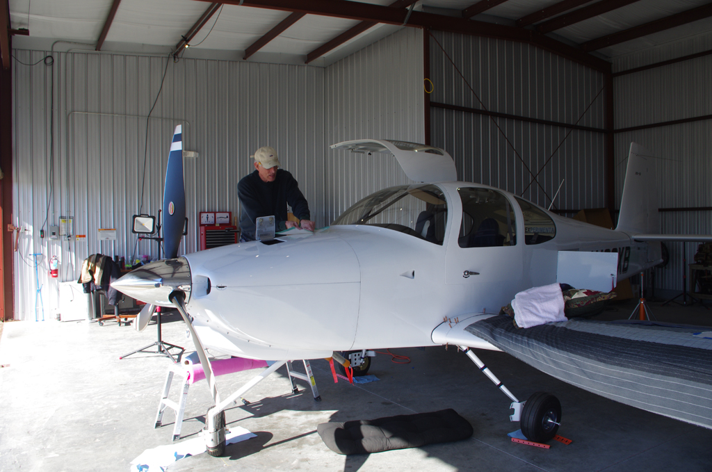
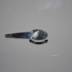
 Aerosport auxiliary seat handles were installed for easier operation. Then final inspection and review of everything to date.
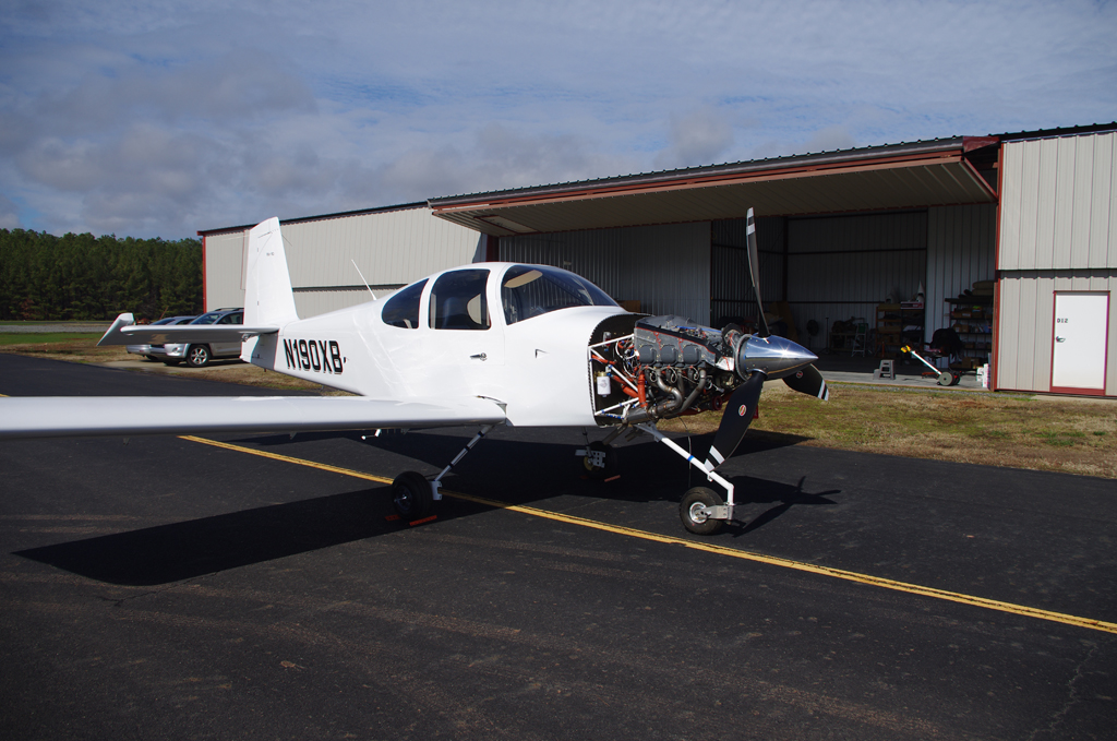
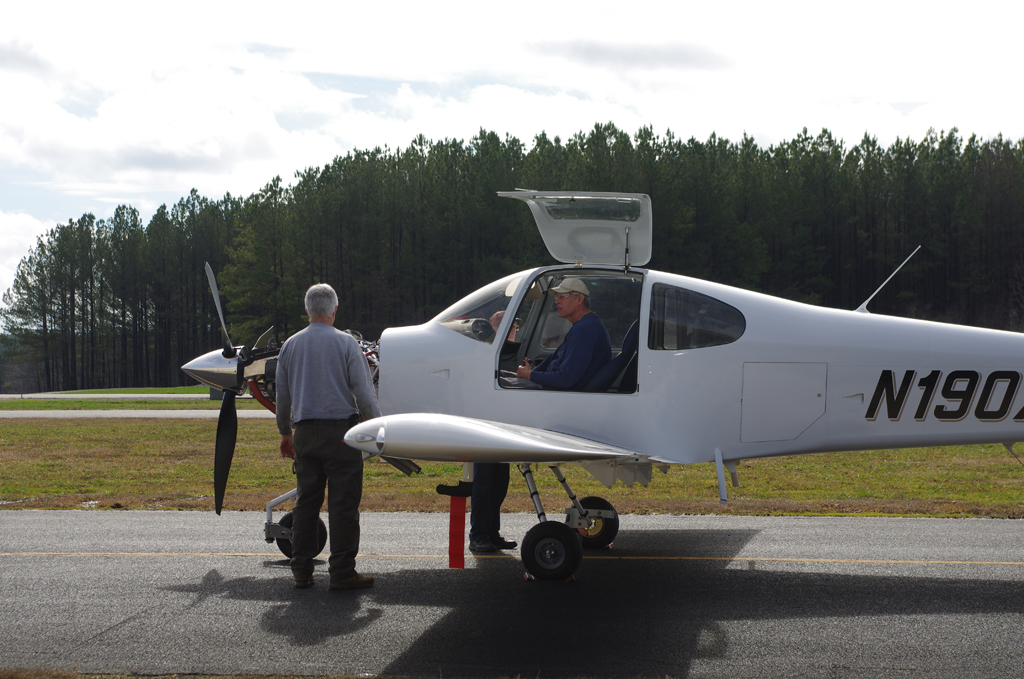
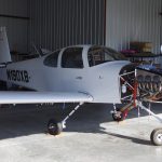
All that’s left before first engine start is sit back and wait for good weather outside. It certainly has been a long time coming. Very excited about this next major milestone.