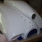
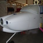
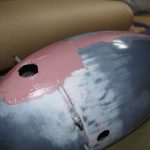
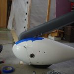
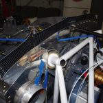
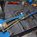
Gear Leg and Wheel Fairings (1)

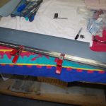
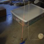
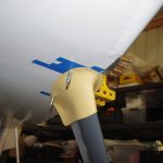
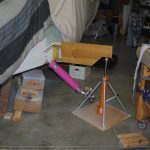
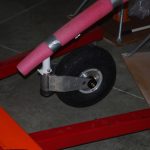
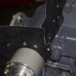
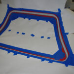
Aligning and fitting the wheel pants required use of two lasers, one for the aircraft centerline and one for accurately locating the pant retention bracket holes.

The fuselage had to be leveled, then raised so wheel installation would leave the wheels just touching the ground. Here the wheel dollies from Charlie Derk (with many thanks) were removed for actual wheel installation.


The main wheels and brake fixtures were bolted into place. Again the plane was leveled and wheels just barely touching the ground.


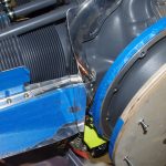
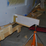
A .75″ x 1.0″ spacer block established the upper position of the main wheel pant. With the forward and aft sections clecoed together, alignment to aircraft center and level reference datum could proceed.


A regular construction laser provided an accurate centerline for the airplace. Measuring offsets to this reference line and the front/aft of each wheel pant ensured parallel alignment. The pants were also measured from the floor to their own centerlines to make sure they were parallel with the ground.


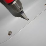
A second construction laser provided accurate location of the holes drilled in the retention brackets. The same processes described above were used with both main pants and the forward wheel pant.


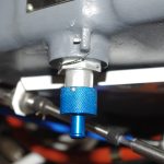
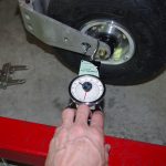
The forward wheel was first installed, then the side breakout pull of ~25lbs was measured with a baggage scale. The Nose Fork Assembly nut was tightened to approximately achieve this value.  I have heard from other builders that this nut will need adjustment many times during the fly-in period.


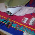
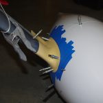
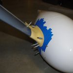
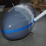
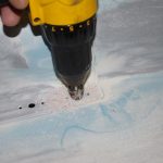
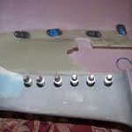
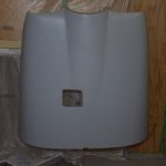
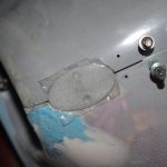
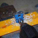
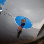
All wheel pants drilled and temporarily clecoed in position in the left photo.  Forward wheel pant protectors were then aligned and holes drilled to prevent two bar damage.


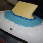
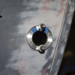
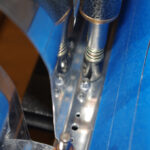
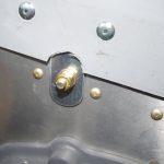
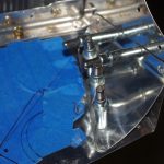
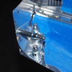
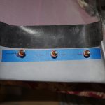
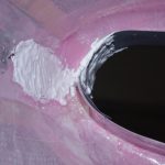
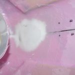
Finally for this section, the pant retention brackets were surrounded with resin/silica to provide larger bearing surfaces during normal flight operations between the fiberglass and the brackets.  Additional resin will be applied in a later post to round over and slightly enlarge the bearing points.


MISCELLANEOUS

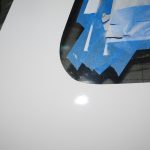
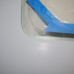
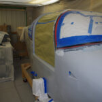
The door windows were retaped prior to the next batch of final paint.


The inital painting of the horizontal stabilizer left a few runs and some flaking along the trailing edge of the upper side.  Resanding and air brush priming were performed before another (hopefully final) paint coat was applied.


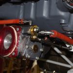
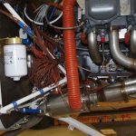
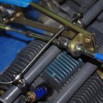
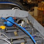
The #2 cylinder fuel injector line required two adel clamp locations to secure between the prop governor cable bracket.

Spinner and Cowling (2)

More fitting and body work has been associated with the upper and lower cowling. The sequence I used for painting the cowl parts:  cut and fit the cowl as needed, sand/putty for initial prime, attach hinges and fasteners, Smooth Prime, sand/spot putty, prime again, scuff with Maroon scotchbrite, and final paint.  Splitting the lower cowl before final prime to accommodate a three-bladed prop was a difficult process.

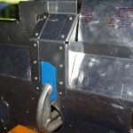
Fitting the lower cowl bracket and bending the air outlet louvers were the beginning final cowl preparations.


Holes for the Skybolt camlocks were drilled with a Unibit into the lower cowl where the air scoop will attach.


Superfil was applied to the air inlet ramps of the upper cowl for smooth airflow into the engine compartment.


Sanding the air inlet ramp and application of resin/glass bubbles to secure the Rod Bower scoop inlet piece were also done.


Drilling for the nose connection screws and aft pin retention block were completed on the upper cowl before the final separation.


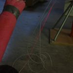
Fishing line (hard to see in the left photo) provide a trace line for the center cowl center. The lower cowl was held together with a forward custom retaining piece while a curf-less saw started the cowl splitting process from the aft side.


Further splitting of the lower cowl continued with the scoop installed until full separation was achieved. The split process was nerve racking, but seems to have been successful.


On the left, the lower split cowl near the aft section is shown held together with a custom retaining piece. On the right, the side hinges were then riveted using a pneumatic squeezer.


Side piano hinges are shown with intermediate and final rivets.


A thin layer of West System resin and colloidal silica was spread to the upper side hinge rivet lines.  After 24 hours of cure time, the layers were sanded smooth before Smooth Prime was applied.  Another round of sanding in preparation of the final prime coating.


Here the rivet lines on the firewall hinges for the upper cowl are filled, then sanded smooth.


After the first coat of primer was applied, some body work or spot putty was needed in some locations. Those areas were then sanded smooth for another round of priming.


After the initial prime, Skybolt fasteners were applied to the lower cowl halves and the lower firewall brackets.  All the parts were then sanded again and reprimed.


Final prime on cowl parts.


Fitting the Aerosport side cowl pin retention blocks and the Skybolt Camlock pins were the last steps before final paint was applied.


MISCELLANENOUS

The flaps were the first set of completed parts transported from the workshop to the airport for staging in the final assembly operations.


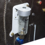
Oil lines were covered with firesleeve, then run from the engine mounted adapter to the remote oil filter on the firewall.


Cowl Baffling (1) and Miscellaneous Items

Preparation of the cowl baffling proceeded in parallel with the initial cowling work.  I was essentially trying to optimize parallel work time utilization – while the resin dried on the cowls, progress was made on the  baffles.

Back riveting on the forward air dam material is shown on the left.  Rough fitting the air dams is shown on the right.


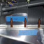
The Vans plans call for fixed height, riveted deflectors in front of the #1 and #2 cylinders.  Experience from other builders indicated these may need trimming to optimize airflow inside the upper cowl chamber.  I elected to install #8 nutplates instead of rivets to allow easy removal of these parts for trimming or total replacement of these as needed.


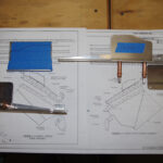
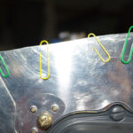
Here the famous “paper clip method” was used to establish a 3/8″ gap between the solid air dam sides and the upper cowl surface. The trim lines are the final dimensions of the metal side plates.


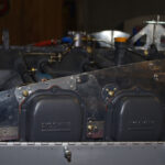
Because the metal sides were so thin above the #1 and #3 cylinders, reinforcing backing plates were fabricated out of .032″ sheet aluminum to provide so additional strength.


The cylinder profile was created on construction paper to get a general outline. Then McFarlane air dam material was measured and cut.  Pliobond adhesive was applied and spring clamps used to press for curing.  This process did not produce great results, as the McFarlane material seems to have a siliconized coating to reduce friction against the inner cowl surface.  Probably great for this purpose, but not helpful when attempting to bond with other materials.


The inner side of the McFarlane dam material appears to be some form of rubber, while the outer side is smooth and laser etched to help conform bend to shape.


The rear baffle panel was backriveted into place.  Now that rivets have been applied, removing the combined pieces from around the motor mounts will be quite difficult.  It was a tight fit beforhand getting the separate parts located around the cylinders and over the mounts.


To finish the back baffle panel a hole for the propeller governor cable needed to be drilled. This required the final configuration of the cable mounting bracket to the prop governor.  Notice how the #3 cylinder fuel injection line is configured to clear the bracket and cable.


The side panels for #5 and #6 cylinders have access ports to allow socket wrench insertion for spark plug maintenance.  These holes are covered during normal operations with removable components to prevent air loss during flight.


Side gussets were custom formed for the front baffle plates, then riveted into place.


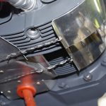
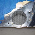
The left front baffle was drilled and opened for one of the heater induction air ports.


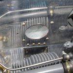
The front heater induction port has a meshed screen installed, then rivet into place.  At right, transitions between the upper and lower cowl faces were applied for a smooth surface.


Before fitting a special baffle around the prop governor, the simple gasket was replaced with one have a filter screen.  Fitting the special baffle over the prop governor should help with air loss.


The forward baffle seals were created with the default Vans material.  On the right the distance between the prop governor and the upper cowl was measured with a piece of modeling clay.


This photo shows the final baffle seals around the prop governor.


The right front baffle before and after the seals are pop riveted into place.


Seals were measured, cut, and Pliobond for the lower cowl air inlets from the default Vans material.


Final fitting of the Aerosport pin retention blocks and applying resin/glass bubbles around the edges.


Here the pin templates are shown from the interior space after raw application of just the resin/glass mixture.  At right is the final configuration with four layers of 6oz fiberglass applied.


Aluminum backer plates were fabricated for inside the pin block cavity.  The plans did not call for these, but I wanted additional rigidity for this area. The plates were relieved in the middle for access to the side piano hinges.


The side fiberglass was also relieved to match the backer plates, then clecoed in place for a final coating of Superfil to create smooth edges.  At right a kerfless saw separated the two cowl halves which had been joined by the pin retention cavity build process.


MISCELLANEOUS ITEMS

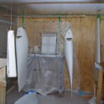
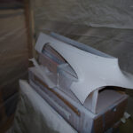
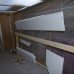
More parts were painted base white…


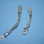
Headliner base repairs and new grounding straps…


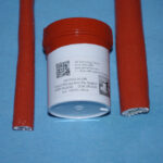
Firesleeve dip for untreated oil and fuel lines…


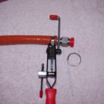
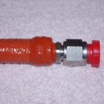
Band-It Jr hose clamps and rescue tape wrappings for final line application (homemade firesleeve solution).


Custom mounting bracket for Matco glass brake fluid reservoir and custom brackets for under-seat line security (fuel, brake, control stick wires)…


Spinner and Cowling (1)

Although I have not posted in quite some time, work has continued on the airplane.  Primary attention has been given to cowl preparation and engine baffling.

The propeller used for the aircraft will be a Hartzell HC-C3Y1R-1N/N7605C three composite blade, hydraulically controlled model.  The recommended gap distance between the rear of the spinner and the forward face of the cowl is  to be no greater than 1/8″ to 1/4″.
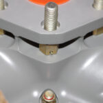


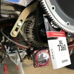
The propeller hub measures 2.5″ from the forward face of the flywheel to the rear face hub bolting location of the spinner retention flange.  The flange spacers are 1/4″ long, the flange itself is 1″ wide, and finally the 1/4″ gap between spinner and cowl means the distance from flywheel face to cowl front should be 1″ apart.  Fine adjustments up to about 1/8″ can be made to the final gap by shimming the spinner flange with washers.
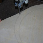


The cowl gap distance seemed difficult to measure accurately without a clearly fixed reference point. I decided to use the face of the flywheel as the starting point for all measurements. Here a plywood disc is measured and cut to match the spinner diameter.
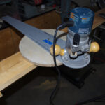


The rough-cut spinner disc was rounded smooth using a router. The 1″ cowl gap was simulated with smaller discs made of plywood and plastic sheets.
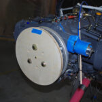


The mounted reference disc shows where the forward face of the cowl should be.  All cowl alignment measures were taken from here.


This photo shows aligning the center of the spinner disc with the crankcase split.
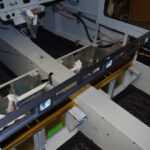


To properly align the cowling, the fuselage must be leveled laterally.  The leveling points are between the door bulkheads in the center of the cabin.
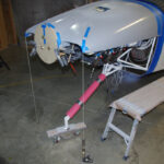


Next the forward face of the upper cowl is positioned behind the spinner disc, then leveled left-right with the floor using plumb bobs.
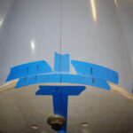
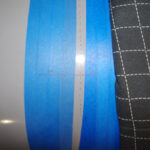


Level references are marked at the front and rear of the upper cowl.  These are used during the trimming process.
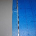


The first trims are for the firewall gaps on the upper cowling.  Anything between 1/16″ to 1/8″ is considered acceptable.  Too tight is not good due to paint chipping and difficult fit, while too wide impacts airflow and does not look good. The key for appearance is uniform width along the length of the gap.
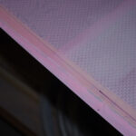


Next action is position the piano hinges and match drill for fit.  Unfortunately, the upper cowl fiberglass had reinforcing honeycomb too close to the edge for the hinge to lay flat.  That honeycomb had to be sanded back and layered with fiberglass to provide sufficient edge strength for piano hinge rivets.
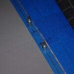
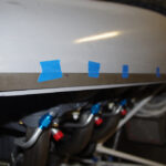


On the left the final upper gap is shown – a bit less than 1/8″.  The right photo shows initial reference line for the cowl side gap.


Once marked the upper cowl side edge was sanded flat with a 24″ sanding block.  This edge became the reference for the lower cowl adjustments.  Four inch spacer blocks were attached between the upper and lower cowls, then measurements from the side reference line to the lower cowl.
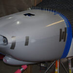


The initial cowl side gap is shown here.
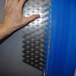


The hole pattern was used to layout locations 1″ apart for the firewall side piano hinges.  The resulting pattern established the permanent gap a bit less than 1/8′.


The same patterning process was performed on side piano hinges.
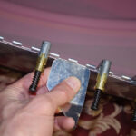


A spare piece of .030″ aluminum with one side covered with self-adhesive sandpaper was used to create a uniform distance from the hinge web to the fiberglass edge.  The lower cowl was drilled from the inside out, then clecoed in place.
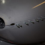


The forward section cowling was roughly cut for the outline of the Aerosport pin retention plate.  The right photo shows the first smoothing steps on upper cowl.
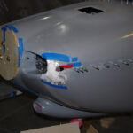


The forward edges of each cowl did not align properly, so resin/glass bubbles were applied to provide a smooth transition.  Next the final fitting of the pin retention template was completed.
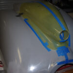


The Rod Bauer air scoop was positioned above the Van’s default scoop and correct dimensions for the cutout were made.  The forward face of the scoop must be about 1″ behind the swinging propeller arc, so very careful measurements were required.
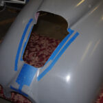


Puckered and pulled the trigger on the pneumatic cutting wheel to remove the Van’s scoop.  This action left a hole just big enough for the K+N air filter housing of the Rod Bower system.
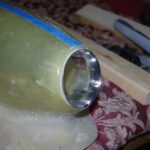


A test fit of the air inlet ring was made, followed by an initial resin/glass bubble layer around the scoop perimeter.
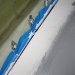


Multiple sanding and filler applications built up the edges between the original cowl surface and the newly introduced air scoop. Clecoes roughly 2.5″ apart securely held the scoop in position.
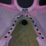


With the external portions of the scoop under way, the internal locations of Camlok fasteners were determined.  As with earlier described issue on the honeycomb webbing, the fastener bases needed relief and then reinforcing for a flat base.
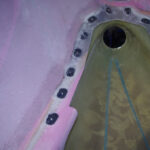
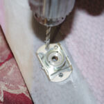


Small base templates were used during the build-up stages, but a real Camlok served as the real template for fastener attach holes.
Engine Installation (1)

International travel to visit family (first time in two years), supply chain issues and the Thanksgiving holidays have slowed the progress towards mounting the engine.  Many of the jobs performed before the engine was mounted would have been nearly impossible with restricted access from the motor mount and in close proximity to the firewall.  Advice to any builder – attach as many components as possible while the engine is still not mounted! Also pay attention to the sequence of attaching oil filter base, magneto work, tachometer port adjustments, and vacuum pad alternator.

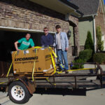
After three years of storage in my garage, it was finally time to move the Lycoming YIO-540-D4A5 engine to the shop for installation.  My sons helped me load and unload the palleted engine onto Tal’s trailer for transport.


My biggest fear from the whole storage period was corrosion of the camshaft due to moisture exposure over time. This proved not to be the case, as Lycoming had done an excellent job of sealing the engine in the crate.  The dessicant indicators looked just like new when the protective plastic was unsealed!


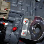
One glitch in the process was Lycoming had sent incorrect 19770 mounting brackets (2″diameter hole) packaged inside the plastic seal instead of the correct 70456 (1.25″ diameter) intended for the Dynafocal mount on an RV10.  Because of holiday staffing at the factory, it took over two weeks to receive the proper brackets.  The time was used to connect as many items as possible on the firewall side of the engine.  At right are the fittings to the engine-mounted fuel pump.


Additional fittings were installed for the oil cooler lines, manifold pressure and tachometer port. I decided to use a magneto mounted Hall Effect RPM sensor instead of a mechanical tachometer converter simply because of eliminating moving parts where possible.


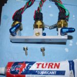
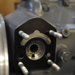
Oil thermostat and temperature sensor on the left.  The Airwolf remote oil filter base adapter in the right photo proved difficult to mount.  The lower right bolt required a special crows foot wrench and many 1/6 increment turns to get attached, then torqued properly.


Safety wiring the oil base adapter was also a challenge – mostly because of my inexperience with the process, but also because of confined geometry.


The remote oil cooler fittings were attached and clocked to point towards the direction of the remote housing.  Next was installing the RPM sensor on the right magneto, then fastening with safety wire.


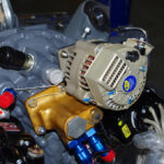
Originally I wanted to install a 60amp backup generator (BC462-H), but the diameter of the main housing was about 1/8″ too big.  It bumped up against the Airwolf base adapter just enough to prevent a clean insertion of the spline and flat attachment against the pad. The smaller 40amp BC410-H fit perfectly. The space to access the lower left stud is very cramped.


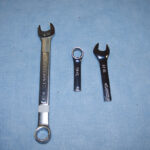
Tools were modified to achieve some attachments. A normal 9/16″ box wrench was ground to gain access to the back nuts on the engine dog ears, especially the lower ones.  A 7/16″ wrench was cut to 3″ to allow the open ended portion to tighten the backup alternator lower left nut.  This was the most difficult task of all.


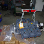
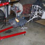
The engine is shown on the hoist ready for attachment.  The Lord J3804-20 isolators were taped into place to facilitate the mount process, which I was able to do by myself. The AN7-26A bolts took a bit to align, but eventually slide into place.  The actual mounting task lasted about one hour.


Here is the engine installed after so many years of preparation. Quite a satisfying accomplishment.

Other builders have suggested  allowing about a month before the cowling should be fit.  This time allows the rubber isolators and engine to settle into their final configurations. Next up will be baffle configurations and more painting.


MISCELLANEOUS

Custom brackets were fabricated to hold the aft door open sensors.


Prime / Paint (3) and Landing Gear

The last eight weeks or so have been all about preparing for the initial base coat of paint on the fuselage.  This includes sand, prime, sand, fill, prime, sand, sand, sand…   and more sand to get the Desoprime surface ready.  The prepped surface was scuffed with maroon Scotchbrite and/or 320 grit paper as indicated in the PPG specifications.

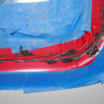
The door windows had some small gaps between the fiberglass frame, the Lord adhesive bonding agent, and the actual plexiglass/Lexan (not sure which) panes.  These gaps were filled with dye blackened resin infused with glass beads. The cured gaps were then sanded, masked and painted in the same interior Boeing 707 Grey as the rest of the interior.


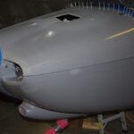
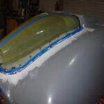
The fairing between the upper fuselage and the windscreen was carefully sanded smooth for a nice transition. I spent much time working on this, as from esthetic perspectives this location is generally a focal point of bystander attention.  The fiberglass fairing was sanded, primed, filled, sanded and primed again three times in an effort to get this right.


Even the three prep cycles did not remove all the pinholes and spots in the primer surface.  In a few locations spot putty was used to fill small voids.  These were airbrushed with primer for coverage before paint was applied.


Curiosity over how the N numbers would cover the tailcone side wall got the better of me.  Here 12″ high sheets simulate the space taken across the panel.


LANDING GEAR

With the body work mostly complete on the stable trolley, it was finally time to mount the fuselage on the landing gear. Custom spar extensions were used to elevate the fuselage to provide clearance for inserting the main gear struts.  These are very sturdy and heavy steel legs with machined attach points which must slide into the gear brackets. The original fits were not good, requiring hours of sanding/fitting to get the struts into proper alignment.

Here the jack stand hold the primary weight of the fuselage, the trolley only serves as a safety block should hydraulic pressure be lost in the jack.


The oleo dampers (nose gear elastomers) are comprised of four rubber discs captured by the nose gear link assembly.  New dampers are quite rigid and must be squeezed to get the bolts installed correctly.  A 3″ strap clamp wrapped around the motor mount provided the necessary compressive force for this operation.


After almost five years on the trolley, the fuselage finally can stand on it own!  With 250 pounds of weight attached to the motor mount, the tail just barely balances to stay off the ground, so a safety block in the tiedown bracket will prevent any tipping which could possibly occur.


Here are some views with the trolley removed.  To me this is starting to look like a real airplance.


Attaching nutplates for the wing root fairings was the last mechanical step before the end game on paint preparations.


PAINT

At the start of this project I had the arrogance to want to the paint the entire plane myself.  However, the experience of massive sanding efforts to correct my poor priming results convinced me to engage a professional for this task.  Here Mack is inspecting the bottom surfaces before applying paint.
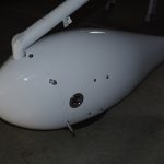


Six coats of Desothane CA8800 I1222 Snow White paint now provide the base color on the fuselage. The painted surface is excellent (barring the wavy results from my amateur body work skills).  Very happy with this outcome and look forward to mounting the engine next.


Prime / Paint (2)

I was offline in recent weeks focused on prime and sand fuselage/components for base coat paint.  This work has been very tedious, uninteresting work and has been covered in previous posts.
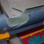
The final paint scheme has been completed, as seen in the new website header. This design evolved from initial thoughts I conceived in Model Plane Color Design V2.4 (MACD) to a professionally structured layout. The final specifications were prepared by Craig Barnett from Scheme Designers. He was excellent to work with and provided very detailed instructions on how to proceed.  I then wrapped this design around a 3D CAD model I have been drafting in Blender for some time. While the model is only roughly proportioned to an RV10, the visual effect achieved should  be a good representation of the final outcome.

The next steps are reline the paint booth with new plastic sheeting and seal for tighter seams.  This will help with better air flow, plus help reduce dust particles from the shop.  Then mount the fuselage on the landing gear legs, mask off the firewall forward components and spray PPG Desothane CA8800 Snow White as the base coat.  I cannot wait for this to happen!

Initial design concept as shown in MACD.


Final design wrapped onto 3D model.


Transparencies and Misc

The templates for masking the window transparencies have finally arrived.  The Avery Dennision BriteLine+ vinyl sheets were custom cut by Moody Aerographics specifically for this purpose.  I originally intended to mask off each window with just one vinyl piece, but matching the template profile on the curved surfaces with the exposed sticky adhesive proved too difficult for an amateur installer.  Instead I chose just to use the corners which lay flat, with electrical tape filling in the straight or slightly curves intermediate sections.

The left photo shows the raw templates on the main roll.  Before applying to the windows, an outline of each corner was traced on acetyl sheets.  The reason for retaining this contour will be shown later…


The left lower windscreen corner was raw fit with epoxy resin and SuperFil before priming.  The corner template mask was laid into the corner with about 1/8″ – 1/4″ offset from the underlaying canopy frame.  This offset will present a clean edge visible from within the cockpit.


The smoothly cut template mask was covered with two layers of electrical tape.  Each tape layer provided an additional 0.0063″ height for when the AlumiLite black dyed and glass bead infused West Marine two part epoxy resin was applied to the edge gap.  The resin will then be sanded carefully from layer to layer to reach the final height of the template mask.


TAPING DETAILS

The same general taping process was then applied to doors and windows.  The raw template mask in the corner was connected to other corners with red electrical tape.  The bright colors for the final tape layer were used to enhance visibility while sanding.  Notice the curved black electrical tape second layer.  This shape was rough cut using the acetyl sheet contour described above. Cutting the electrical tape in this manner helps it stay flat, as compared with trying to bend the tape around a tight corner.


Additional black electrical tape was applied above the straight sections, followed by general masking and one more layer of vinyl tape roughly laid around the perimeter.


These photos show the before and after initial application of the dyed resin for the front left door.


These photos show the rear left window progressing from taped outline, dyed resin applied, initial rough sanding, and final edge sanding.


The last sanding step levels the lowest tape layer with the resin material.  Since this is only about .006″ thick, the care needed to not rub through to the Plexiglass window is extreme. It took quite some time to achieve this on the windscreen, doors and windows. The sanding outcome so far looks good, but application of the primer and paint will show whether the preparations were sufficient.
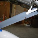


OIL DOOR LATCH BUTTONS

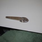
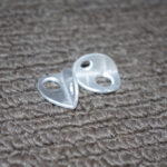
The issue of the push buttons for the oil door has finally been addressed.  A #30 hole was drilled into the Camlock latch plate, then taped for a #6 screw.  A mock-up of the final buttons (yet to be fabricated) are represented by the washers on the right.


The Delta drill press and a V-block were used to drill a 1/2″ steel bar with a center hole.  That hole was then taped for a #6 screw.  The taped post held a piece of 1/8″ aluminum flat bar for shaping.
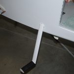


The blank was hand filed and then sanded to exactly fit into each latch hole. The sides were slightly rounded to self-center the button when the latch springs back to the closed position.  The final buttons were polished with 2000 grit sandpaper and fastened with #6 stainless screws. They will probably will be left as-is and not be painted, but that decision will be made later.


MISCELLANEOUS

The original plans call for an AN3 bolt to hold the steps in their cradle.  I wanted a stronger connection, so the steps and the cradles were drilled and reemed to 1/4″ to hold thicker AN4 bolts. (NAS-


The door alarm reed switches were connected to the main electrical bundle via DSUB connectors.  They are held together with heat shrink, then laced into place.


The main wiring bundles on left and right sides under the rear seat panels were laced together.  In retrospect I would probably rearrange some of the wire runs for a cleaner look, but the final result is secure and will be serviceable as needed for future maintenance.


The control sticks were cut to length to provide the maximum height without touching the instrument panel or switches.


Interior (3)

Terminating the headphone and microphone jacks was the last set of main actions needed for the interior fuselage electrical system.  What remained were cable lacing and those connections left for when the engine is mounted.

The center console cover plate and rear face of the armrest are the locations for the jacks.


The mounting components for the front plate are shown on the left.  The rear face mock-up is on the right.


The inner side of each jack location contains a backer plate with holes for the soldered wires and auxiliary devices. On the front plate are spaces for the Bose LEMO jacks and an auxiliary audio input.  The rear face includes a USB power connector with two ports.


Here the front cover plate is shown under the control quadrant.  Note in this photo the hole for the auxiliary audio input has not yet been drilled.
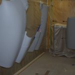


The console parts were laid on their side to trim ins a straight line as shown on the right.  The interior tunnel wiring with fuel pump and transducer wiring is shown on the left.
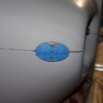


Preparing the headliner material for covering the fiberglass template included steaming to remove wrinkles and cutting to approximate size.  The attempt to cover the fiberglass with material once spray adhesive applied was a total disaster (no photos shown due to the embarassment factor). Fortunately the fiberglass templates were recovered. The covering job will be left for professionals.


Final configuration of the push-pull cables for the fore heater box, rear heater box, and oil cooler valve were also completed on both the interior and exterior side.  These were McFarlane MCU224-xx slip resistant cables in all cases.


The main ground wire under the pilot seat was encased in 7/16″ fuel line to further protect against chaffing against bulkhead parts.  This was probable not necessary given the clearance, but extra precautions for this critical matter were taken.

Control Cables (1)

Installation of the cockpit and firewall sides of the control cables has begun.

These were the initial penetration of the center firewall box prior to applying Lavashield to the surface. Silicone grommets primarily protect the cables from vibrations and chaffing.  The stainless grommet covers are intended to reduce heat/fire to the grommets. They will later be filled with RTV (room temperature vulcanizing) material on the inside to seal out gases.

More details in subsequent posts.