Prime / Paint (2)

I was offline in recent weeks focused on prime and sand fuselage/components for base coat paint.  This work has been very tedious, uninteresting work and has been covered in previous posts.

The final paint scheme has been completed, as seen in the new website header. This design evolved from initial thoughts I conceived in Model Plane Color Design V2.4 (MACD) to a professionally structured layout. The final specifications were prepared by Craig Barnett from Scheme Designers. He was excellent to work with and provided very detailed instructions on how to proceed.  I then wrapped this design around a 3D CAD model I have been drafting in Blender for some time. While the model is only roughly proportioned to an RV10, the visual effect achieved should  be a good representation of the final outcome.

The next steps are reline the paint booth with new plastic sheeting and seal for tighter seams.  This will help with better air flow, plus help reduce dust particles from the shop.  Then mount the fuselage on the landing gear legs, mask off the firewall forward components and spray PPG Desothane CA8800 Snow White as the base coat.  I cannot wait for this to happen!

Initial design concept as shown in MACD.


Final design wrapped onto 3D model.


Transparencies and Misc

The templates for masking the window transparencies have finally arrived.  The Avery Dennision BriteLine+ vinyl sheets were custom cut by Moody Aerographics specifically for this purpose.  I originally intended to mask off each window with just one vinyl piece, but matching the template profile on the curved surfaces with the exposed sticky adhesive proved too difficult for an amateur installer.  Instead I chose just to use the corners which lay flat, with electrical tape filling in the straight or slightly curves intermediate sections.

The left photo shows the raw templates on the main roll.  Before applying to the windows, an outline of each corner was traced on acetyl sheets.  The reason for retaining this contour will be shown later…


The left lower windscreen corner was raw fit with epoxy resin and SuperFil before priming.  The corner template mask was laid into the corner with about 1/8″ – 1/4″ offset from the underlaying canopy frame.  This offset will present a clean edge visible from within the cockpit.


The smoothly cut template mask was covered with two layers of electrical tape.  Each tape layer provided an additional 0.0063″ height for when the AlumiLite black dyed and glass bead infused West Marine two part epoxy resin was applied to the edge gap.  The resin will then be sanded carefully from layer to layer to reach the final height of the template mask.


TAPING DETAILS

The same general taping process was then applied to doors and windows.  The raw template mask in the corner was connected to other corners with red electrical tape.  The bright colors for the final tape layer were used to enhance visibility while sanding.  Notice the curved black electrical tape second layer.  This shape was rough cut using the acetyl sheet contour described above. Cutting the electrical tape in this manner helps it stay flat, as compared with trying to bend the tape around a tight corner.


Additional black electrical tape was applied above the straight sections, followed by general masking and one more layer of vinyl tape roughly laid around the perimeter.


These photos show the before and after initial application of the dyed resin for the front left door.


These photos show the rear left window progressing from taped outline, dyed resin applied, initial rough sanding, and final edge sanding.


The last sanding step levels the lowest tape layer with the resin material.  Since this is only about .006″ thick, the care needed to not rub through to the Plexiglass window is extreme. It took quite some time to achieve this on the windscreen, doors and windows. The sanding outcome so far looks good, but application of the primer and paint will show whether the preparations were sufficient.


OIL DOOR LATCH BUTTONS

The issue of the push buttons for the oil door has finally been addressed.  A #30 hole was drilled into the Camlock latch plate, then taped for a #6 screw.  A mock-up of the final buttons (yet to be fabricated) are represented by the washers on the right.


The Delta drill press and a V-block were used to drill a 1/2″ steel bar with a center hole.  That hole was then taped for a #6 screw.  The taped post held a piece of 1/8″ aluminum flat bar for shaping.


The blank was hand filed and then sanded to exactly fit into each latch hole. The sides were slightly rounded to self-center the button when the latch springs back to the closed position.  The final buttons were polished with 2000 grit sandpaper and fastened with #6 stainless screws. They will probably will be left as-is and not be painted, but that decision will be made later.


MISCELLANEOUS

The original plans call for an AN3 bolt to hold the steps in their cradle.  I wanted a stronger connection, so the steps and the cradles were drilled and reemed to 1/4″ to hold thicker AN4 bolts. (NAS-


The door alarm reed switches were connected to the main electrical bundle via DSUB connectors.  They are held together with heat shrink, then laced into place.


The main wiring bundles on left and right sides under the rear seat panels were laced together.  In retrospect I would probably rearrange some of the wire runs for a cleaner look, but the final result is secure and will be serviceable as needed for future maintenance.


The control sticks were cut to length to provide the maximum height without touching the instrument panel or switches.


Interior (3)

Terminating the headphone and microphone jacks was the last set of main actions needed for the interior fuselage electrical system.  What remained were cable lacing and those connections left for when the engine is mounted.

The center console cover plate and rear face of the armrest are the locations for the jacks.


The mounting components for the front plate are shown on the left.  The rear face mock-up is on the right.


The inner side of each jack location contains a backer plate with holes for the soldered wires and auxiliary devices. On the front plate are spaces for the Bose LEMO jacks and an auxiliary audio input.  The rear face includes a USB power connector with two ports.


Here the front cover plate is shown under the control quadrant.  Note in this photo the hole for the auxiliary audio input has not yet been drilled.


The console parts were laid on their side to trim ins a straight line as shown on the right.  The interior tunnel wiring with fuel pump and transducer wiring is shown on the left.


Preparing the headliner material for covering the fiberglass template included steaming to remove wrinkles and cutting to approximate size.  The attempt to cover the fiberglass with material once spray adhesive applied was a total disaster (no photos shown due to the embarassment factor). Fortunately the fiberglass templates were recovered. The covering job will be left for professionals.


Final configuration of the push-pull cables for the fore heater box, rear heater box, and oil cooler valve were also completed on both the interior and exterior side.  These were McFarlane MCU224-xx slip resistant cables in all cases.


The main ground wire under the pilot seat was encased in 7/16″ fuel line to further protect against chaffing against bulkhead parts.  This was probable not necessary given the clearance, but extra precautions for this critical matter were taken.

Control Cables (1)

Installation of the cockpit and firewall sides of the control cables has begun.

These were the initial penetration of the center firewall box prior to applying Lavashield to the surface. Silicone grommets primarily protect the cables from vibrations and chaffing.  The stainless grommet covers are intended to reduce heat/fire to the grommets. They will later be filled with RTV (room temperature vulcanizing) material on the inside to seal out gases.

More details in subsequent posts.

Interior (2)

Further development of the interior included shaping the headliner backing and configuring the center console/armrest.

A tracing of the side window outline was laid against the fiberglass headliner template from Areosport Products. The fiberglass was rough shaped to the window contours, then finalized when test fitted into the canopy.  Further actions include additional shape refinements and covering the fiberglass backer with grey headliner material.  The lower side panels may also need relief to accommodate the thickness of the headliner at the longeron edge.


On the left are #8 ClickBond nutplates being glued into place.  Regular riveted nutplates could have been used here, but I wanted to avoid additional hole penetrations on structural elements whenever possible. On the right are holes cut into the forward center tunnel covers for heater cables and the AUX COMM connection.


A .060″ stainless backing plate was made for the heater push-pull cables.  They require a D-shaped hole to keep the cable from rotating. Since I was not confident the carbon fiber side panels could withstand the stress without cracking, the approach to spread the forces across a larger area was taken.


Here the Aerosport center console cover was rough fitted to the SteinAir control quadrant plate to the top and to the armrest base on the bottom.  Particular attention was paid to where the fuel selector valve would be located. Notice the small lower seam between the center cover and the armrest base.  This was achieved with a very slight tilt of the cover against the quadrant plate.


Once the test fit of the quadrant plate was complete, the 3/4″ holes for the control cables were made with a Unibit in the drill press.


The throttle cable was checked in the quadrant plate before completing the remaining holes.  The photo at right shows the mounting plate for the center console provisionally attached to the now permanently installed quadrant plate.


The mounting plate viewed from the front and with the center cover in place.


Next was drilling and fitting the Andair fuel valve selector in the lower armrest base. This was done very carefully and required about 6 hours to complete. The #10 screws shown in these photos are too high, interfering with the rotation of the selector.  They must later be replaced with others with a lower head to allow freedom of movement.


Here are interim view of the armrest, center console, side covers, and lower instrument panel. Up next are fitting the control cables, layout and installation of headphone/microphone jacks in the center console, armrest adjustments and other final configurations above the tunnel.


Interior (1)

Interior panels from Aerosport Products were fitted throughout the main cabin.

The rear panels were taped into place for initial fitting.


After sanding to fit the cabin dimensions, mounting holes were drilled to secure the panels in place.  Due to there structural rigidity, only a few screws were needed for each panel.


Once the panels were complete, fitting the rear air vent deflectors was undertaken.  A test fit of the 3D-printed deflector highlights the relative position to the default Vans hole.  A tracing from outside shows the indicated Aerosport cut line not aligned with actual location.


To correct for the actual location of the opening, a probe hole was first opened in the panel.  This was hopefully near the middle of the vent hole.  A file was then used to manually relieve the panel material until just the deflector opening was exposed.


The vent grate is clipped into position with small tabs around the inner edge.  As a result the tolerances for the hole opening are fairly tight. While it took some time to hand file the holes, the alignments and fit are quite good. Minor adjustments are still needed for the vent lever position, but the main rear panel work before painting was done.  Next up is the cabin headliner.

Instrument Panel (6)

Electrical testing with the G3X system continued after installation of the Series 2, 24-pin CPC wing root connectors and other interior devices.

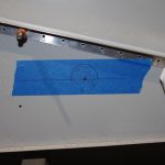
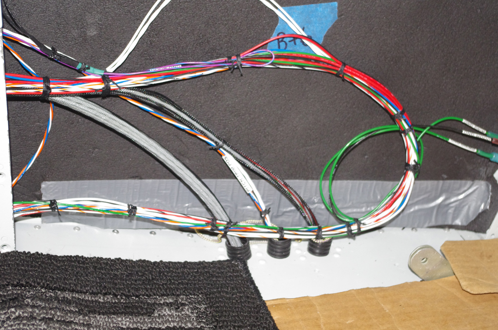
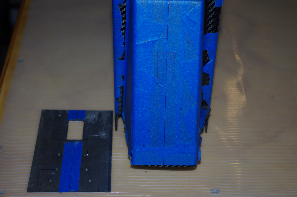
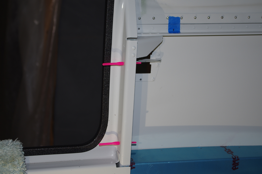
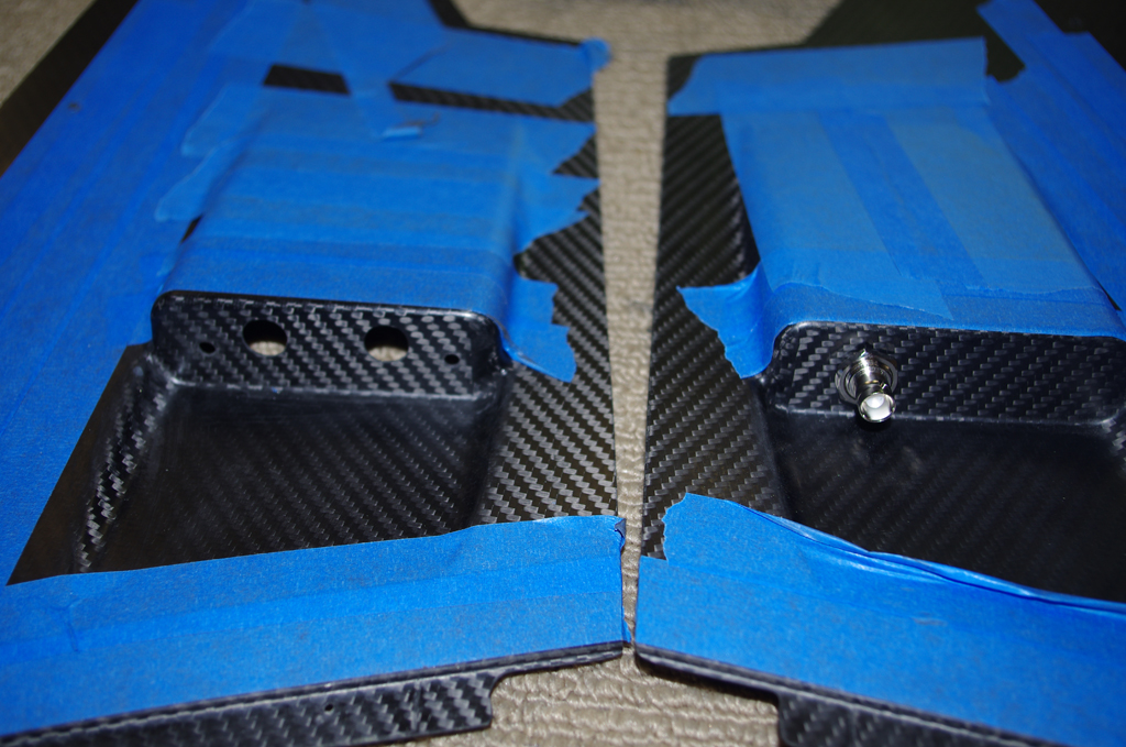
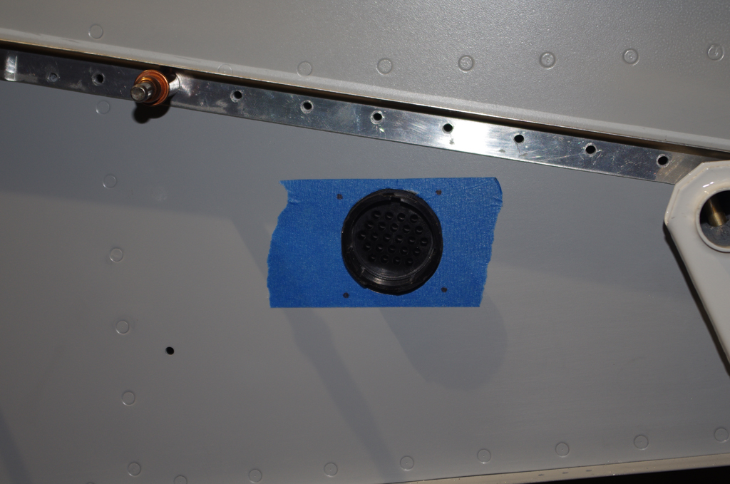
The position of the wing root connectors needed to have enough clearance to be under the wing root fairing, but high enough for easy accessibility in the side panel cavity. Careful measurements were taken before the side penetration was done.


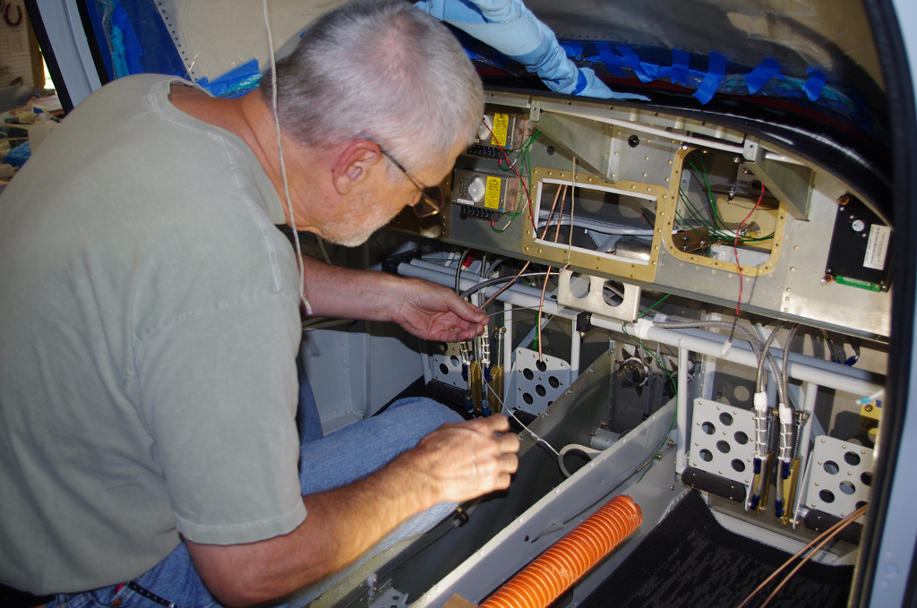
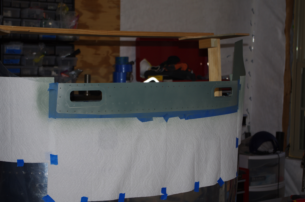
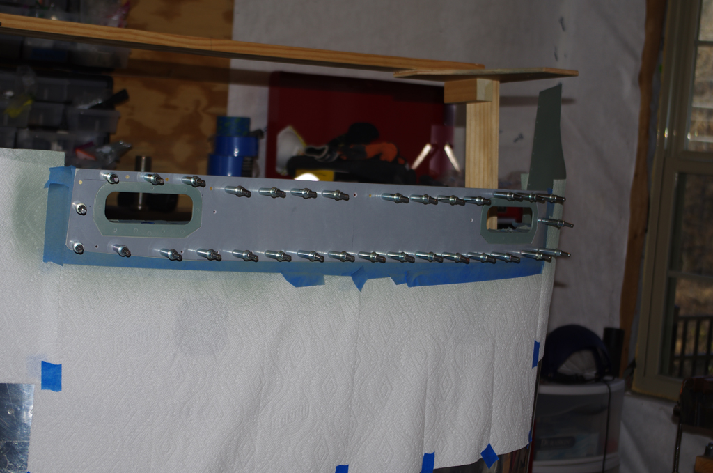
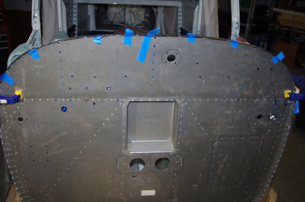
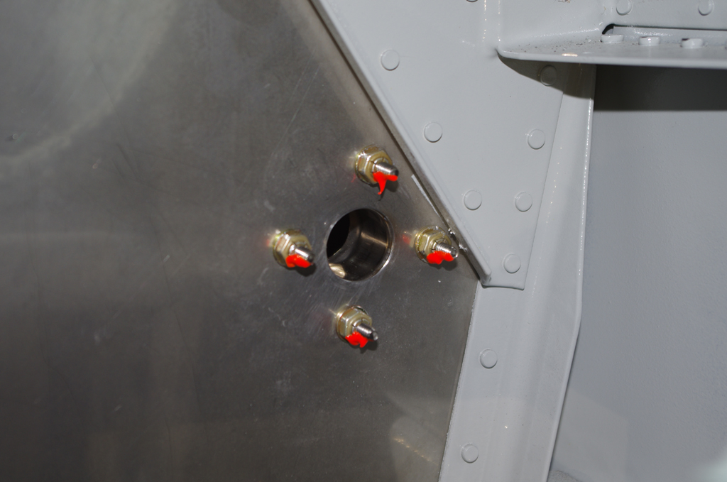
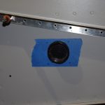
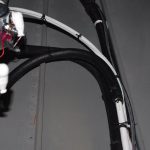
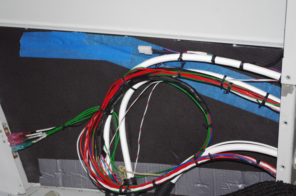
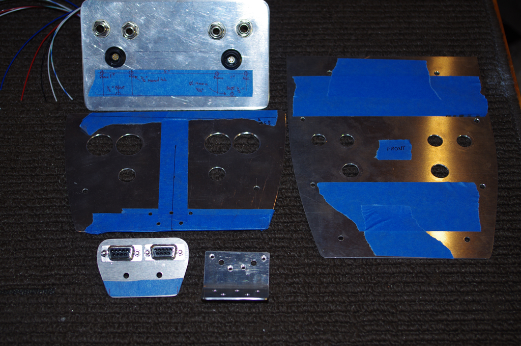
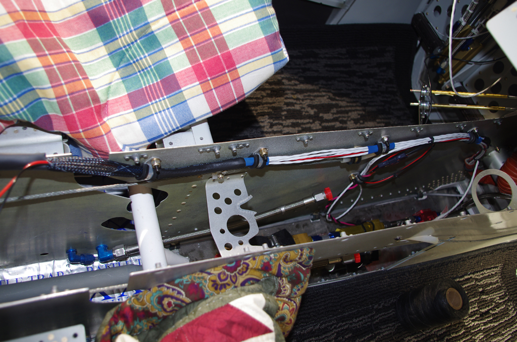
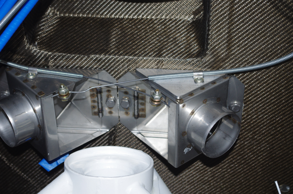
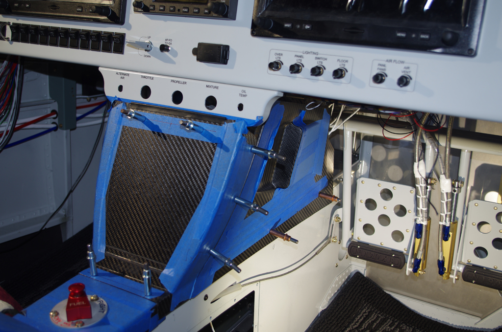
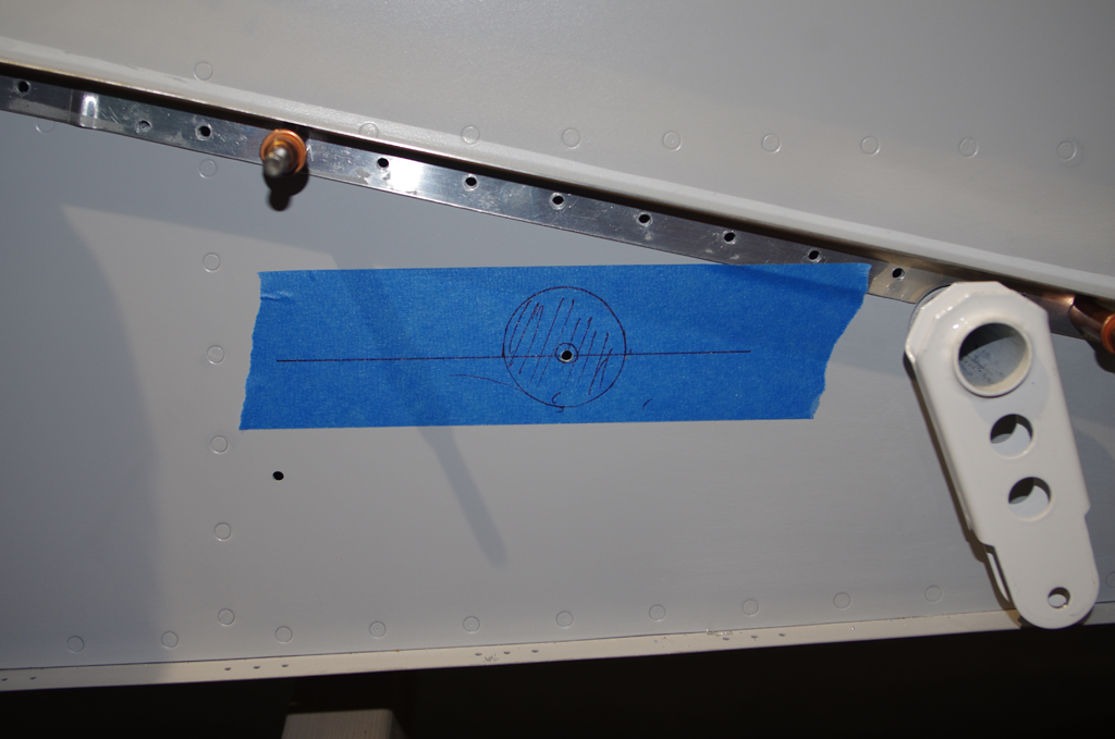
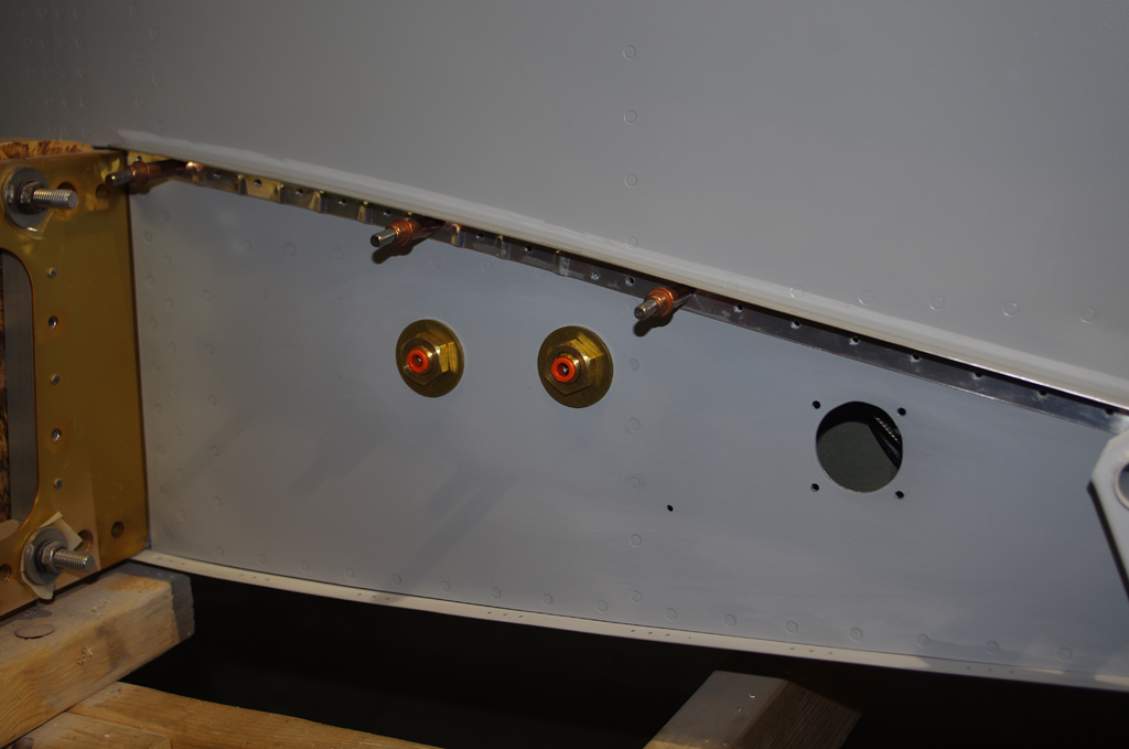
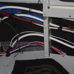
Additional holes in the left side were needed for the pitot and angle-of-attack (AOA) pneumatic tubes.  The left photo shows a trial installation of the brass, right angle push-to-connect bulkhead fittings.  The right photo shows the initially pulled configuration of the side wire bundles.  In retrospect, I would probably rearrange how some of these wires are run.


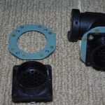
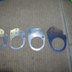
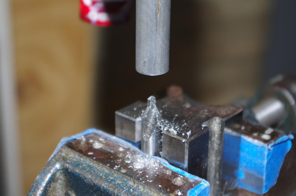
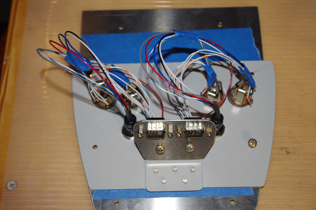
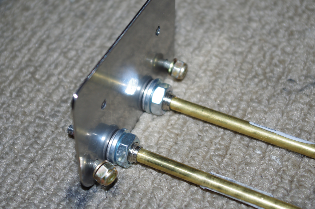
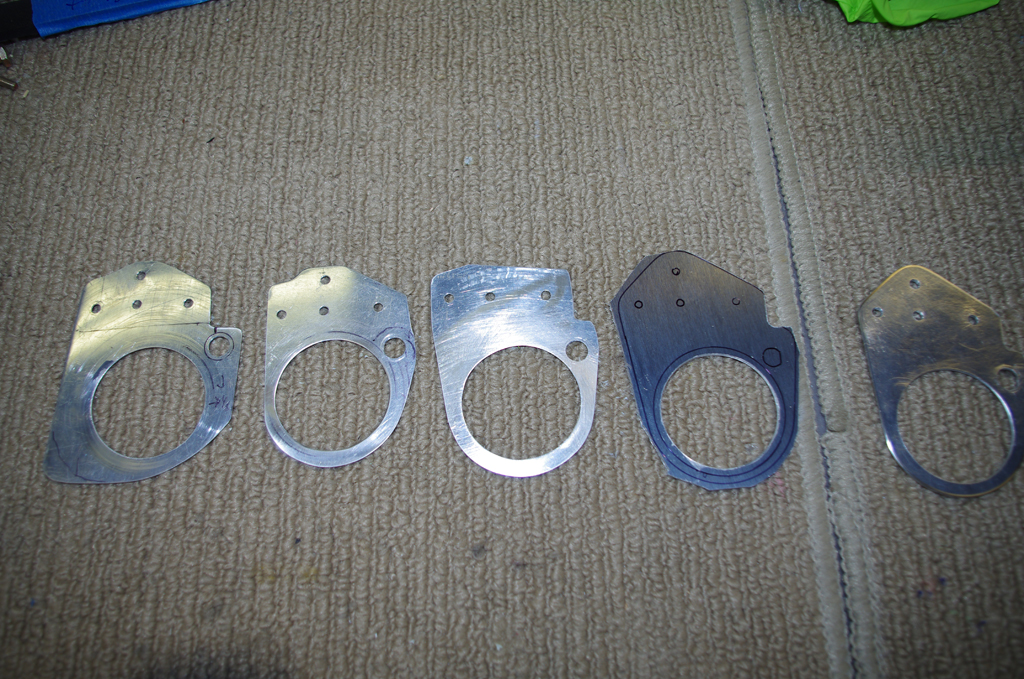
A custom nut plate backer was fabricated for each CPC connector.  This accessory will help fasten the connectors in the fuselage mid-shin.  The right photo shows a right angle strain relief shell and the nut plate backer with the wing root wire bundled pulled through them ready for CPC male pin termination.


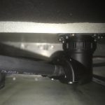
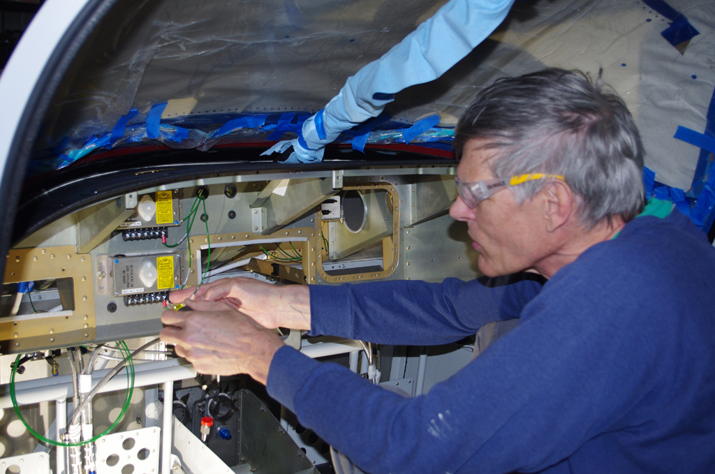
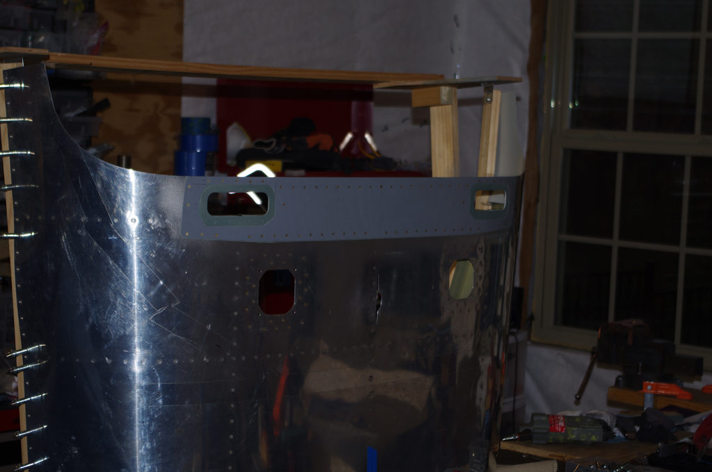
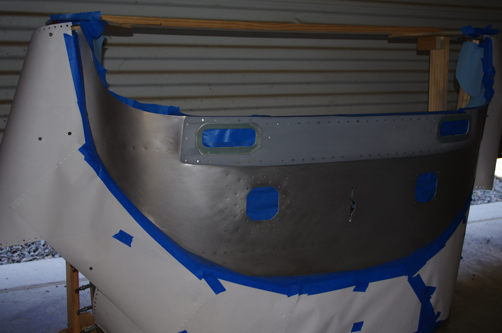
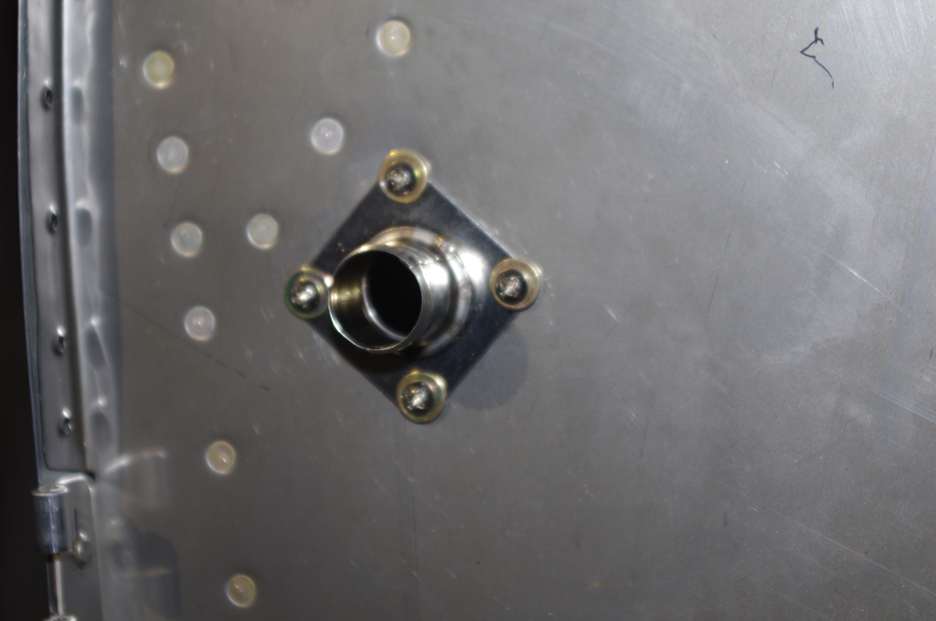
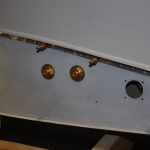
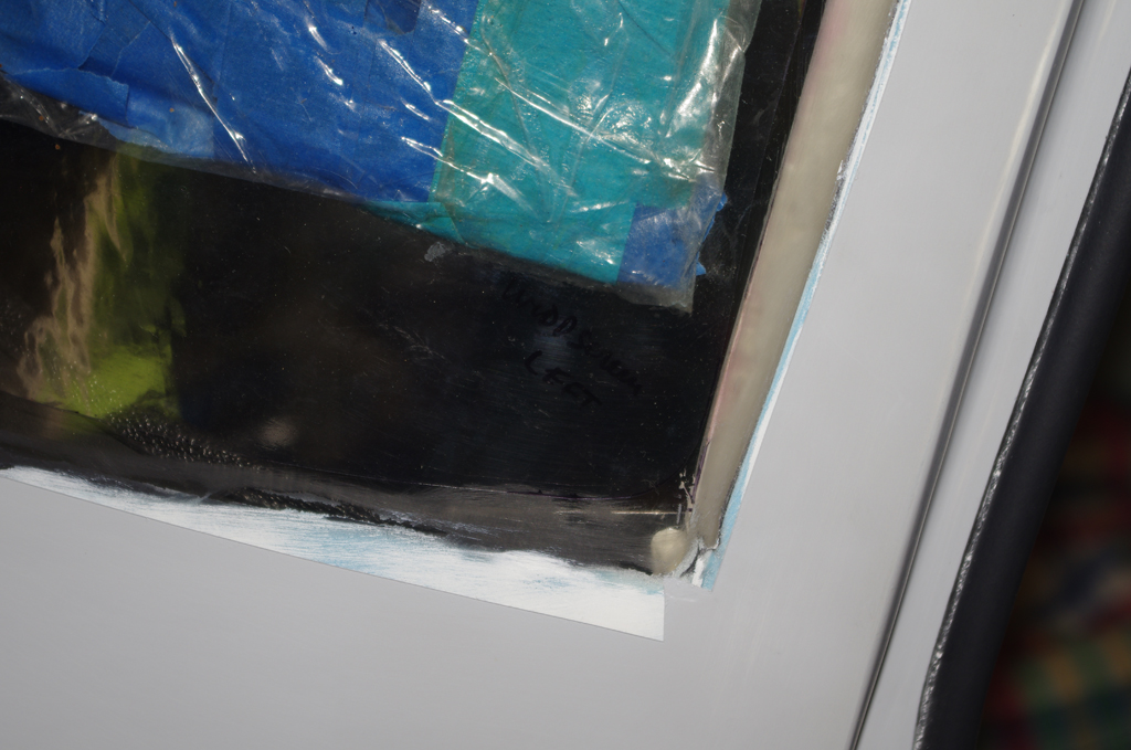
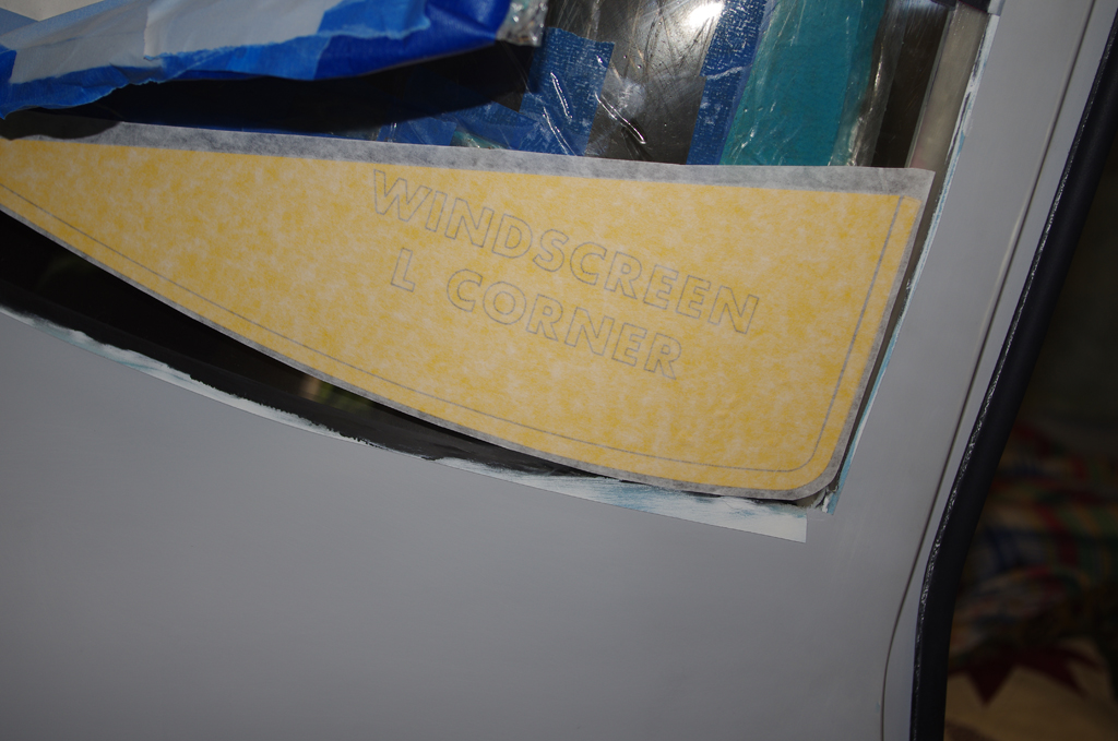
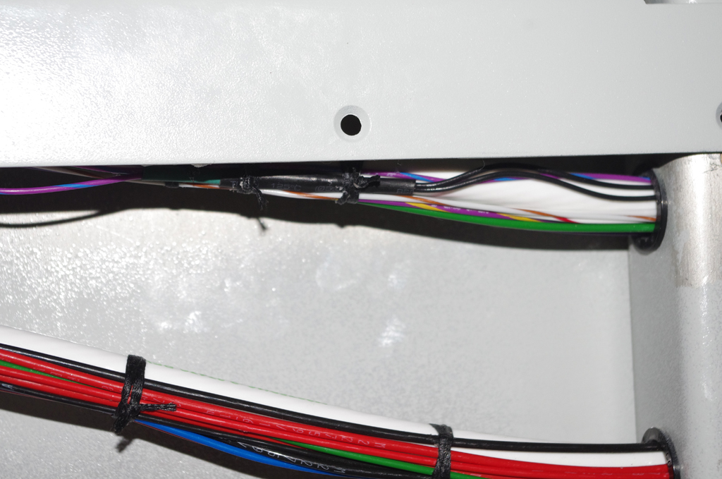
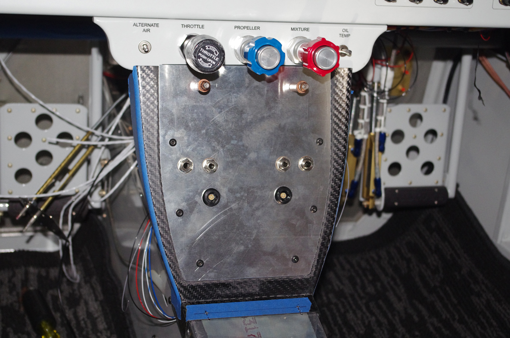
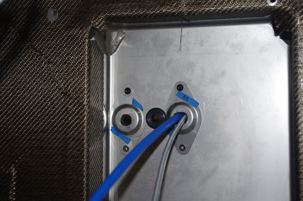
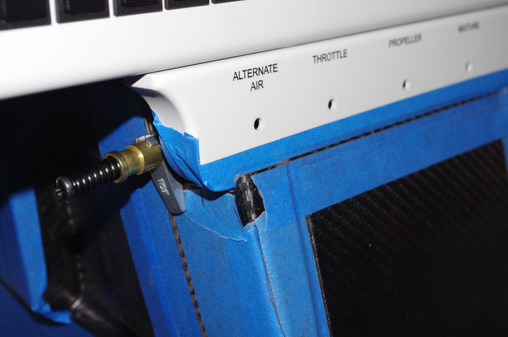
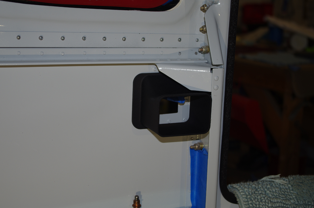
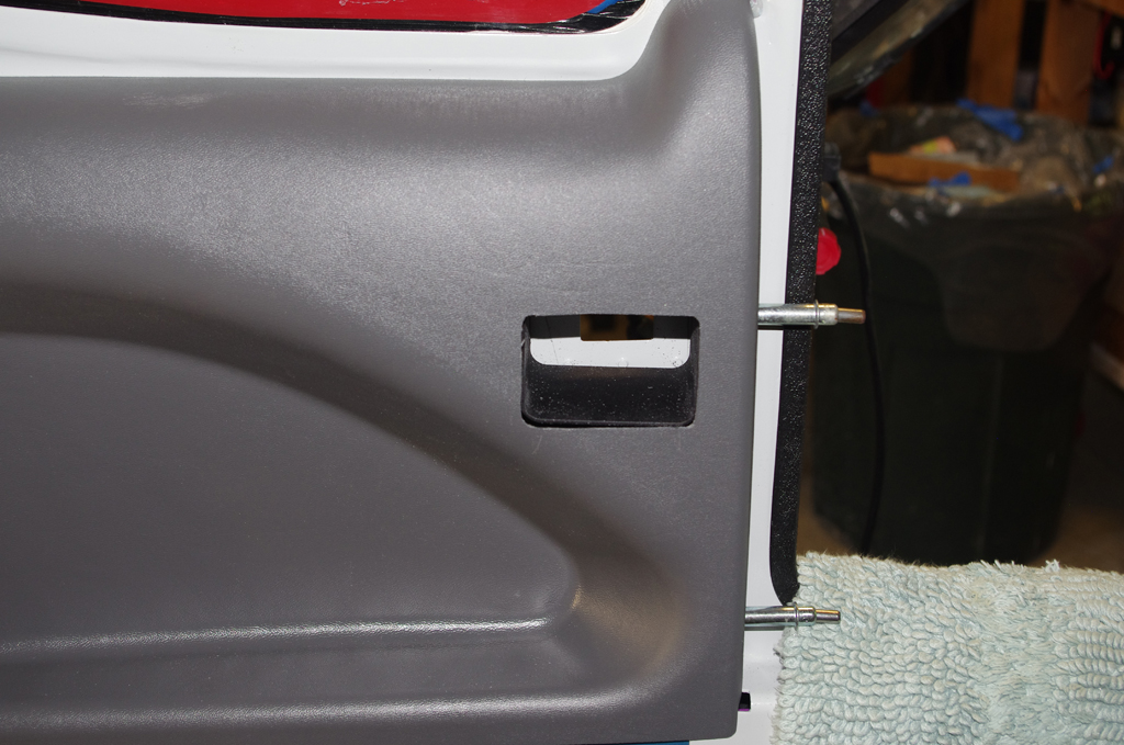
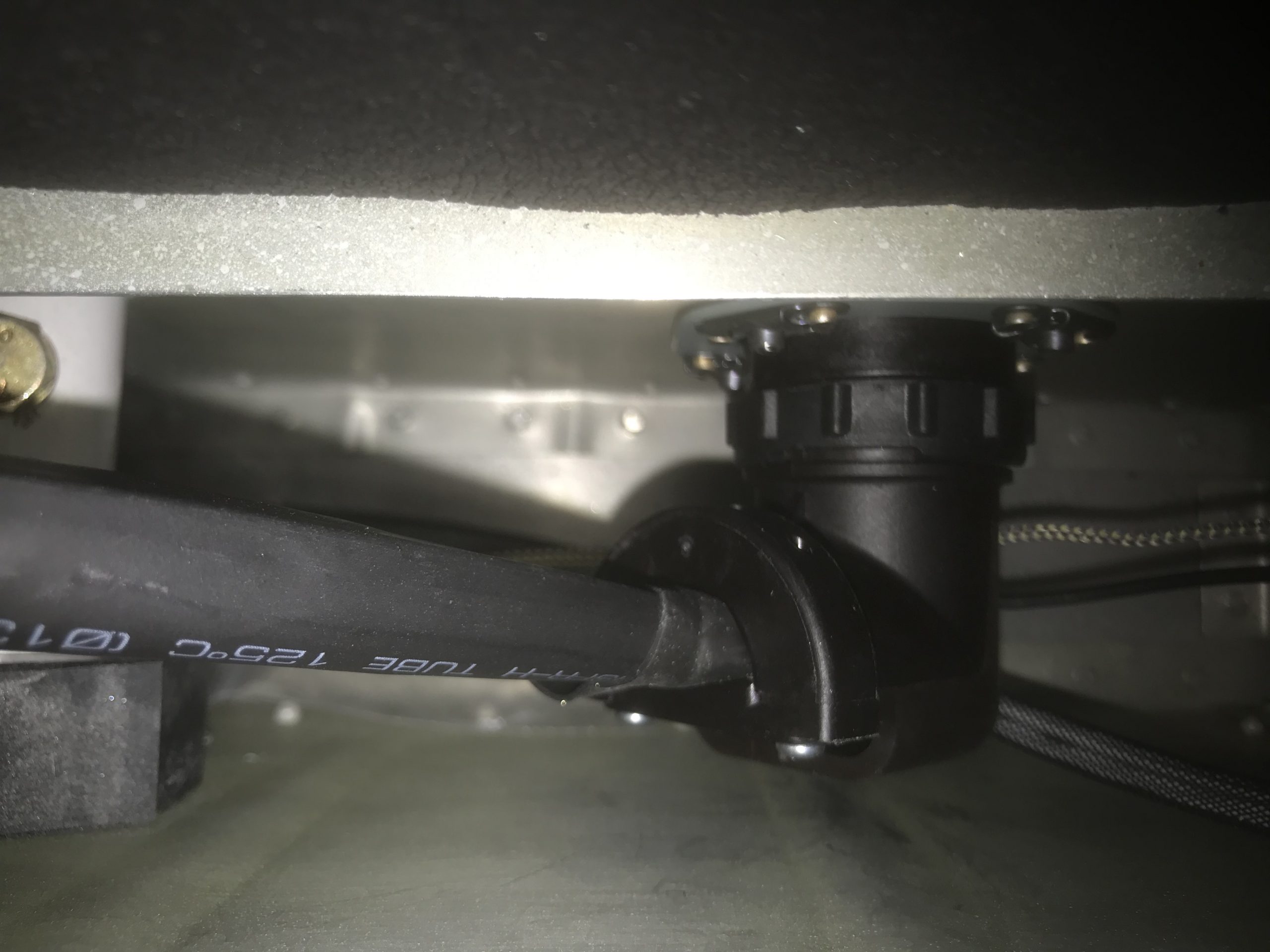
The final CPC configuration – inside the mid-skin cavity and from outside the fuselage.  The outcome was very good (more on the testing later).


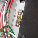
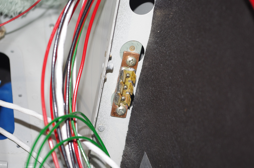
Custom ground block terminators were described in an earlier post.  One of them was installed in the rear seat area for access from the wing roots and the aircraft rear conduits, which feed wires from the rear section under the baggage/seat floors to the forward compartment. The right photo shows a series of prototype brackets for the forward air vents.


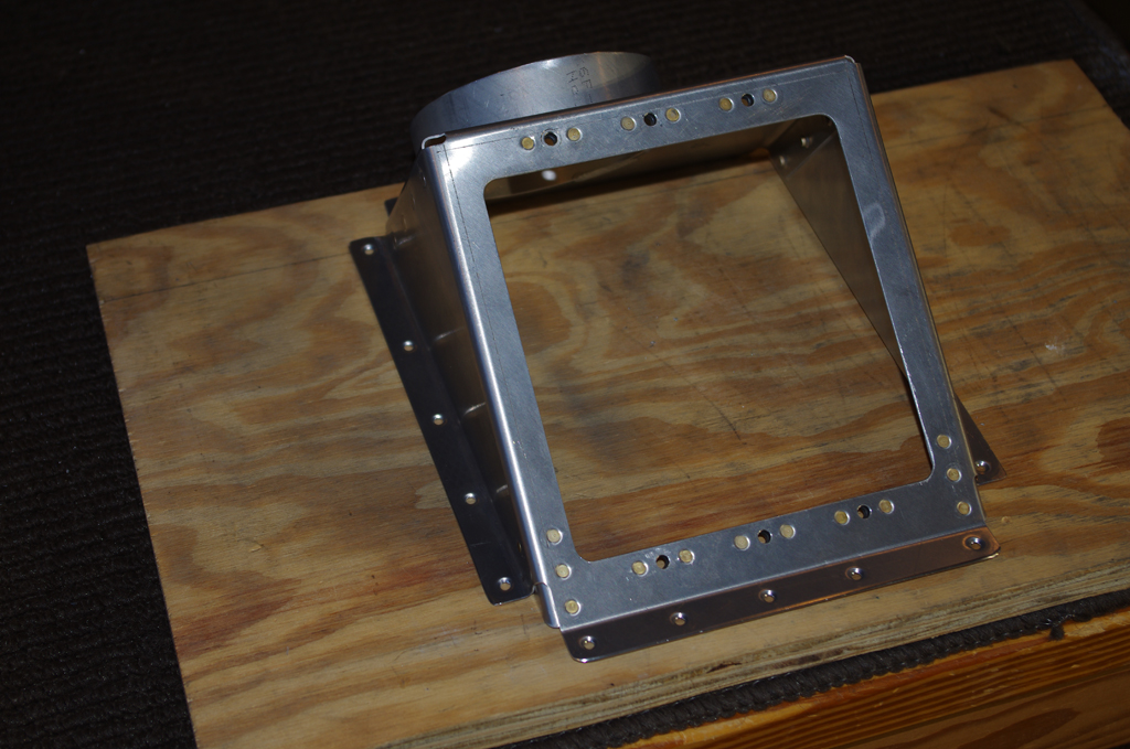
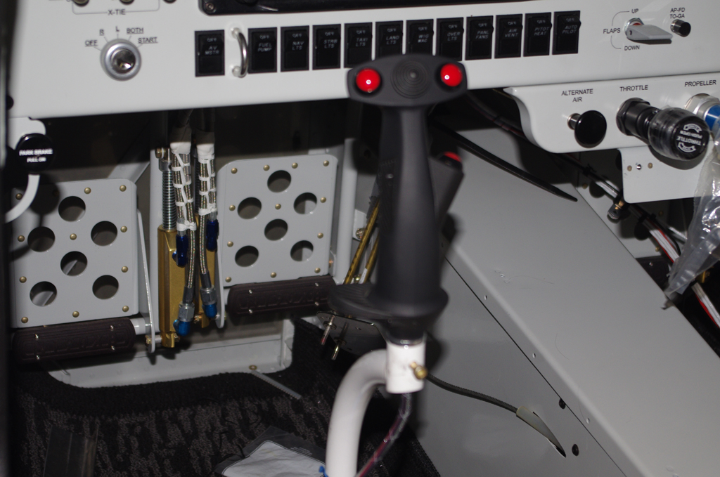
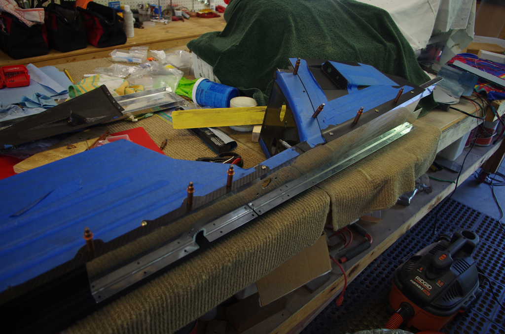
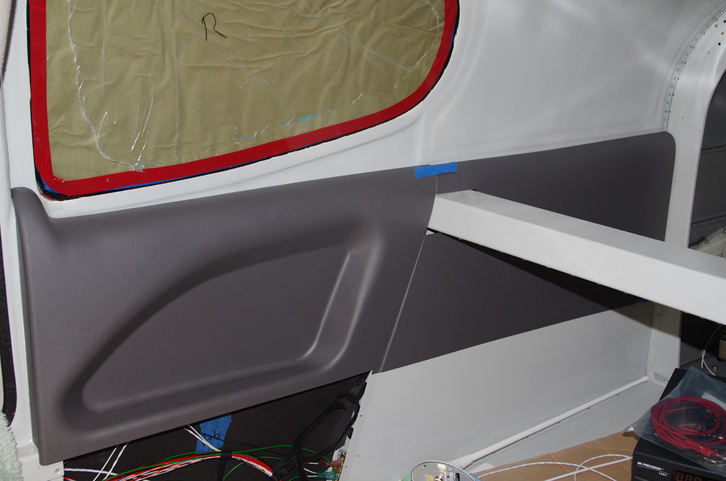
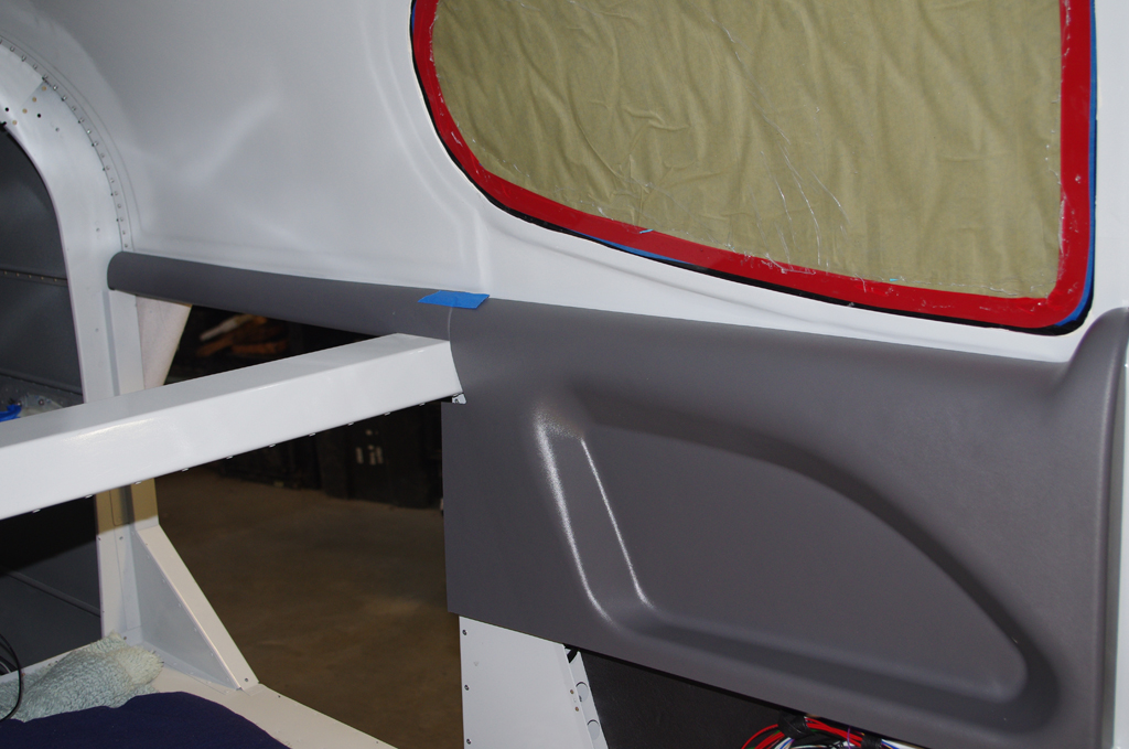
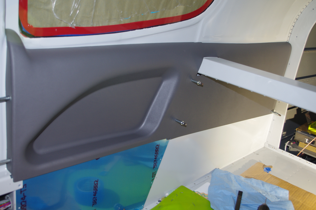
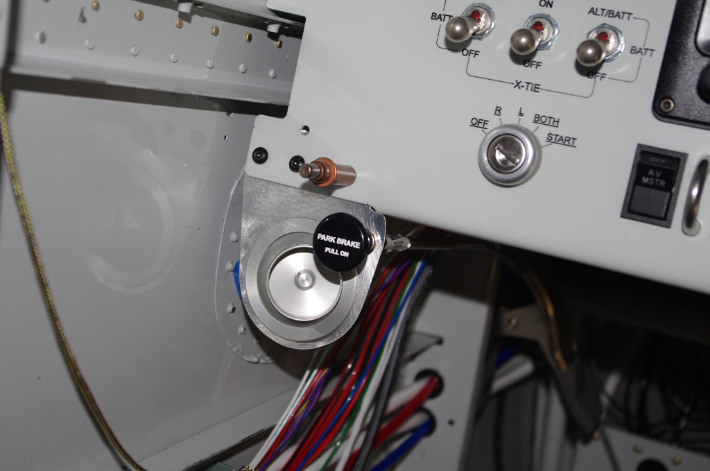
The Park Brake push-pull cable will be located in the left side air vent bracket.  Here a mock-up of the intended configuration is shown. While the vent is close to the brake lever, it does have a free range of motion and should have air flow impacted very much.  The final painted and installed bracket is on the right.


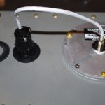
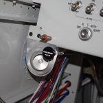
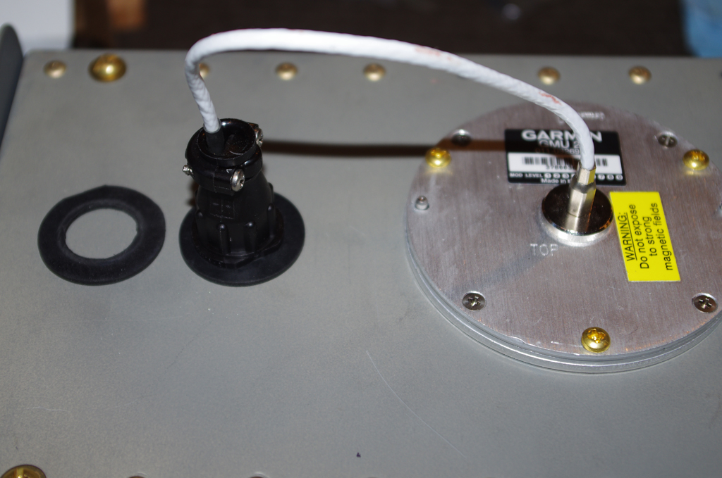
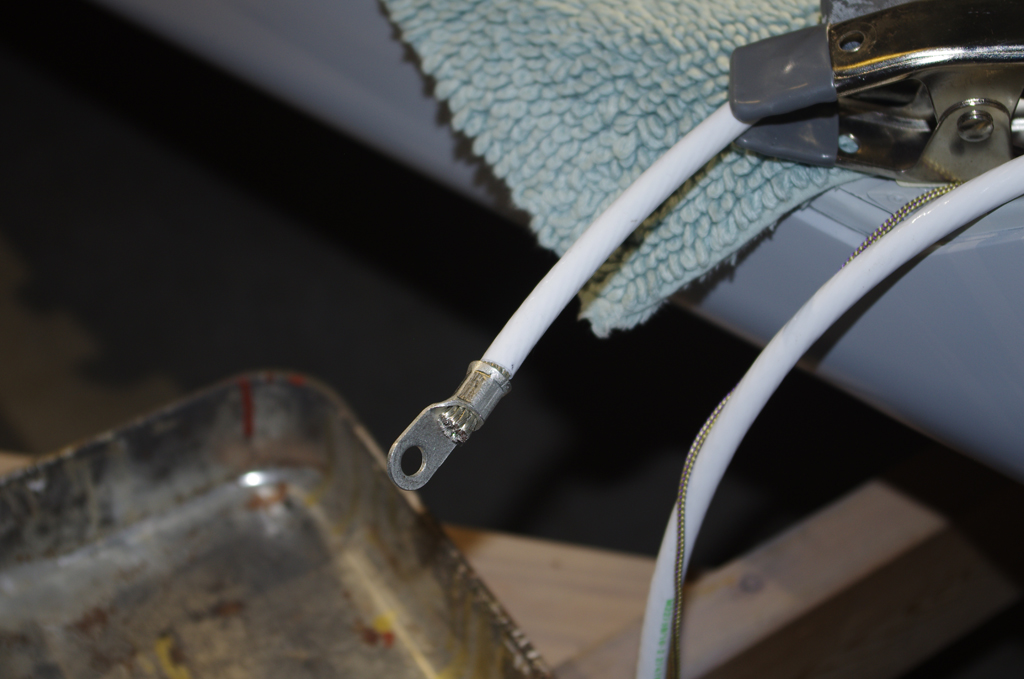
The previously free hanging Garmin GMU22 magnetometer cable was replaced with a custom rubber washer in 5/8″ hole drilled into the mounting bracket.  This new setup now provides secure fastening of the connector to the transmission wiring.


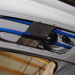
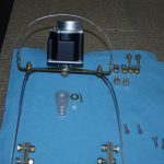
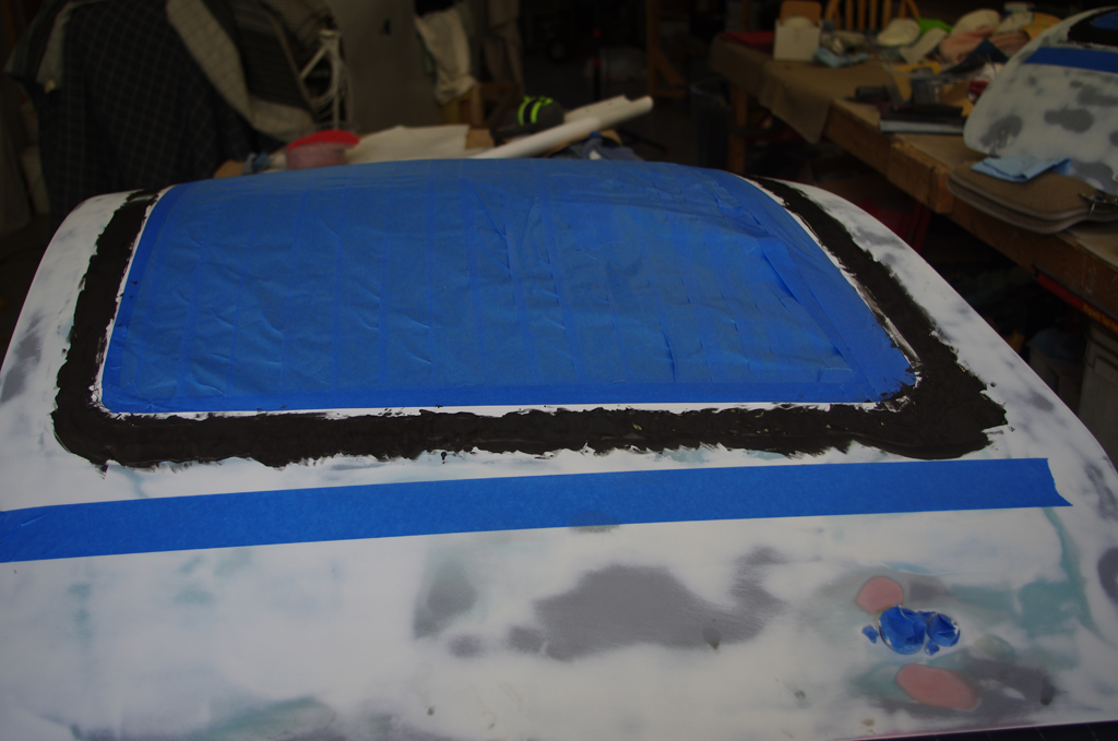
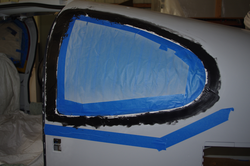
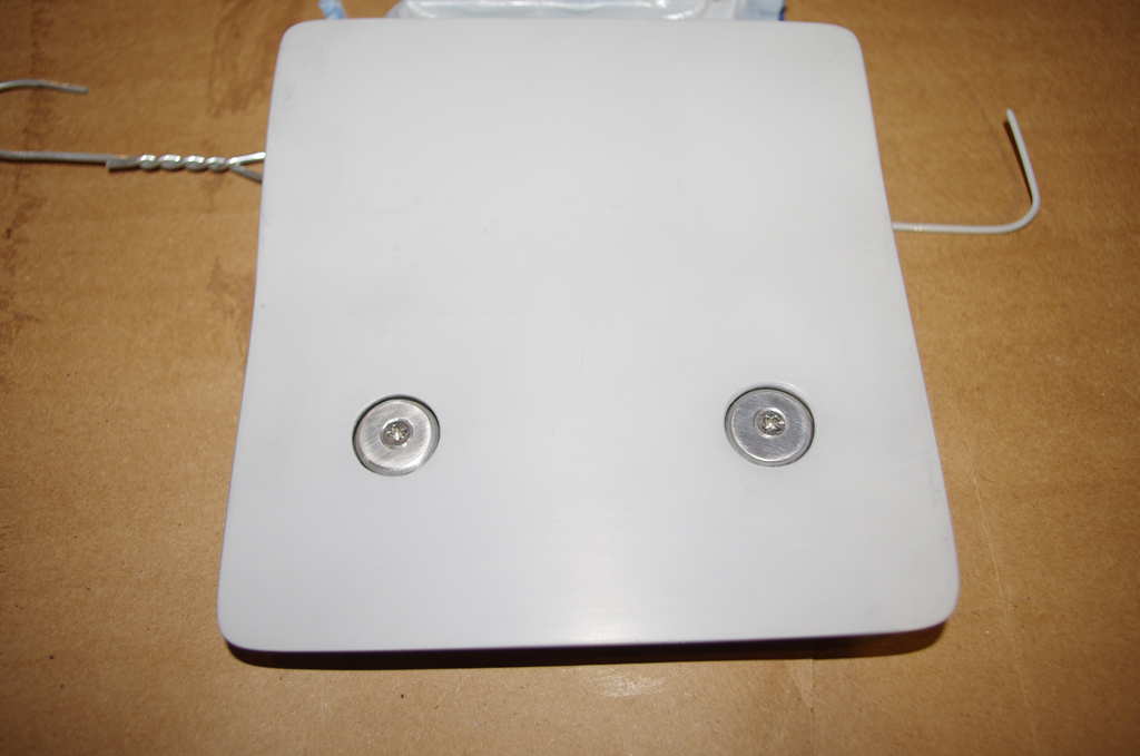
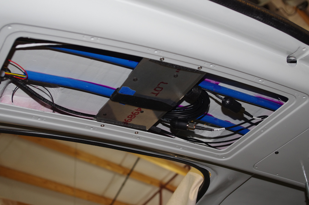
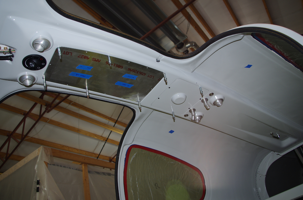
Custom brackets were fabricated to mount the two Garmin GA26C and one GA35 antennas under the fiberglass canopy above the overhead console tunnel. The cover plate will be painted the same interior colors after the shoulder strap and headphone mounts have been attached.  Note the GA26C antennas drive the Garmin G5 and PFD devices, while the GA35 provides WAAS-enabled signal for IFR flight with the certified GNC355 GPS/COM navigator.


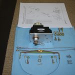
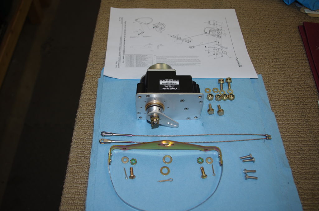
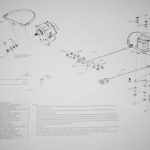
Mounting the Garmin GSA28 autopilot servos to the rear bellcrank mounts required configuration of the movement arms.  The parts for the pitch servo are on the right. A diagram of the yaw servo parts are on the left.


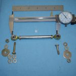
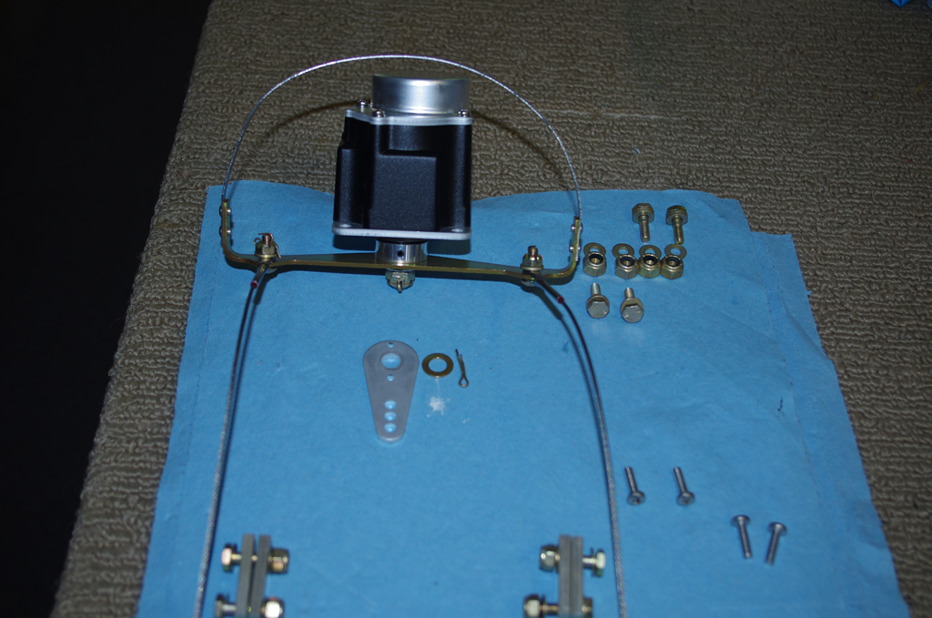
The yaw servo attaches to the rudder cables via a special yoke.  This kit replaces the standard movement arm for the GSA28 servos.


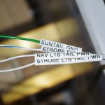
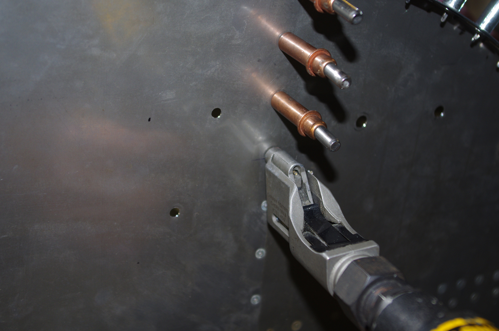
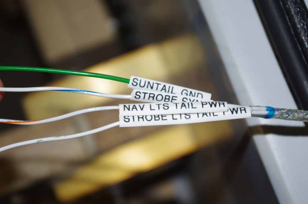
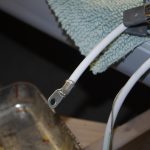
In general throughout the whole build every wire was labelled with the same indications as shown on the AS-BUILT drawing.  The rear AeroLED Suntail wires were no exception.  These were pulled along with NAV2, AUX/COM, and ELT antennas, and pitch trim wire through the rear conduits to the tail.  The #2 Tefzel power and ground wires were then terminated with a 10 ton hydraulic crimper.


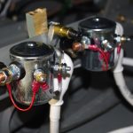
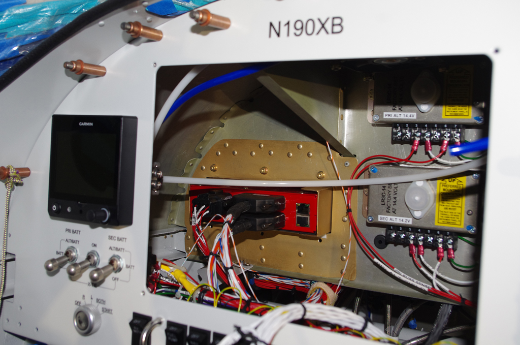
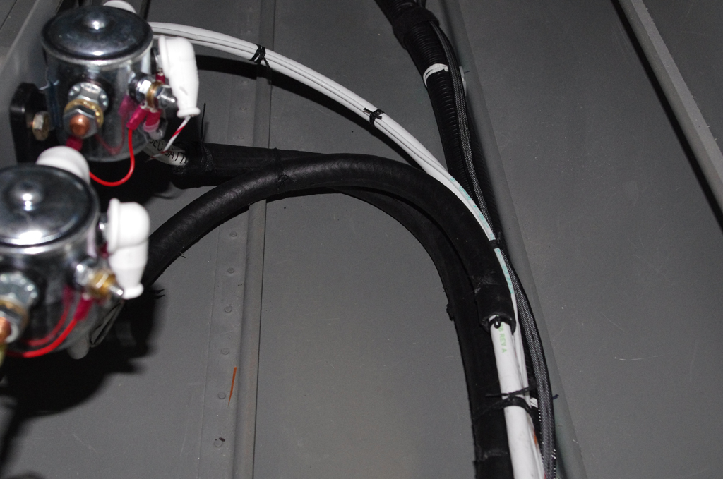
The terminated power wires connected to the PRI BATT and SEC BATT contactors.  The final wires were cable laced with a rubber fuel line as protection against chaffing on the floor and J-channel stringers.


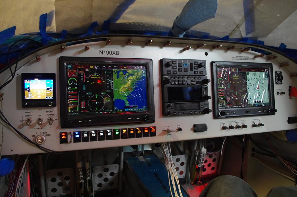
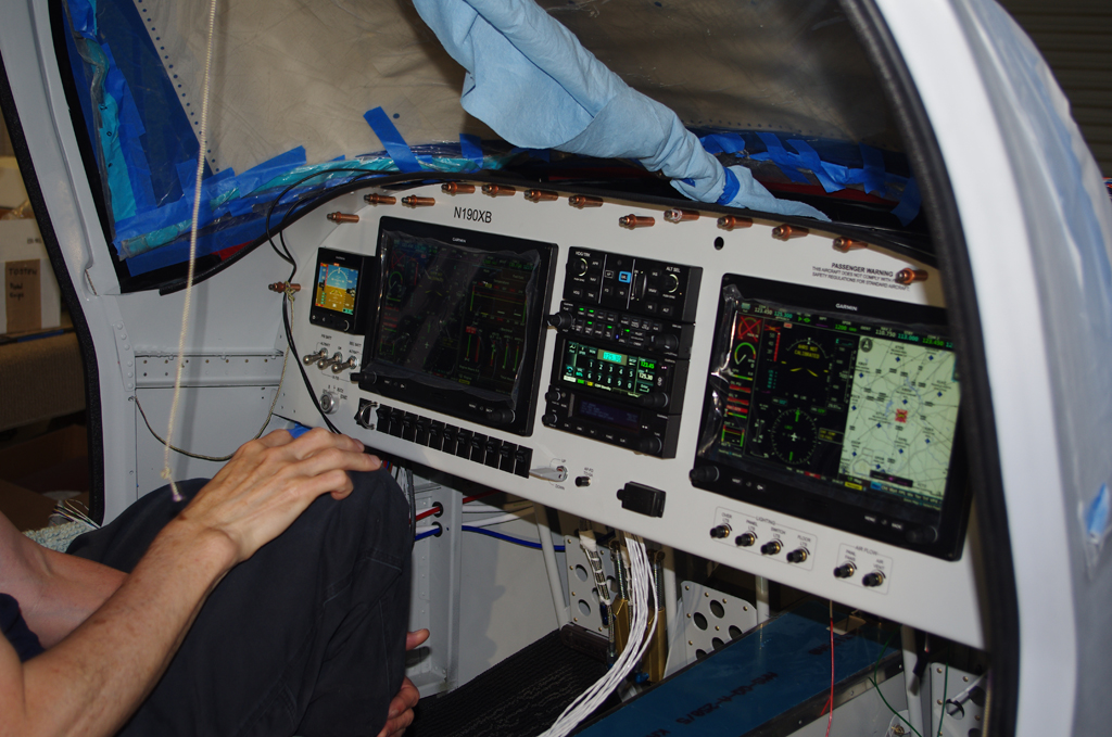
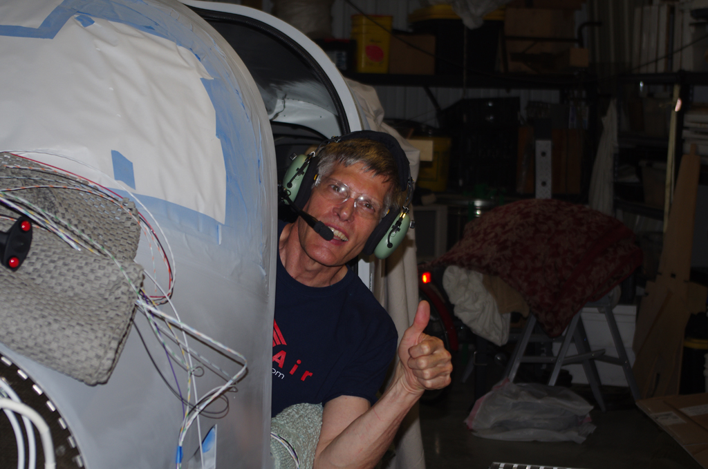
With internal wiring completed a complete range of power on tests were again performed.  The CPC wiring, pitch/yaw servos and trims, battery contactors, flap motor, fuel pump, air vent, transponder, magnetometer, overhead lighting, GPS antennas and other components located within the core fuselage all passed initial functional testing.  While the majority of electrical connectivity has been successfully tested, the remote wing devices and engine monitoring sensors remain.


MISCELLANEOUS

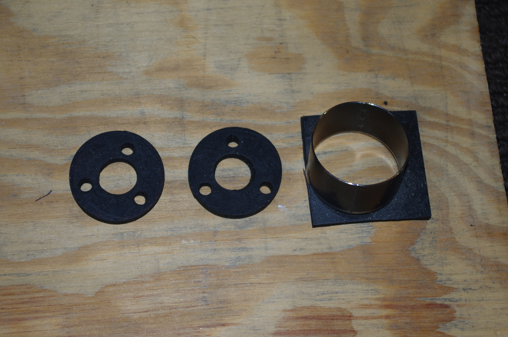
Using leather punches I have started making custom washers from rubber or neoprene sheets of various thickness.  Here are two 1/4″ thick rubber washers for the floor light mounts.
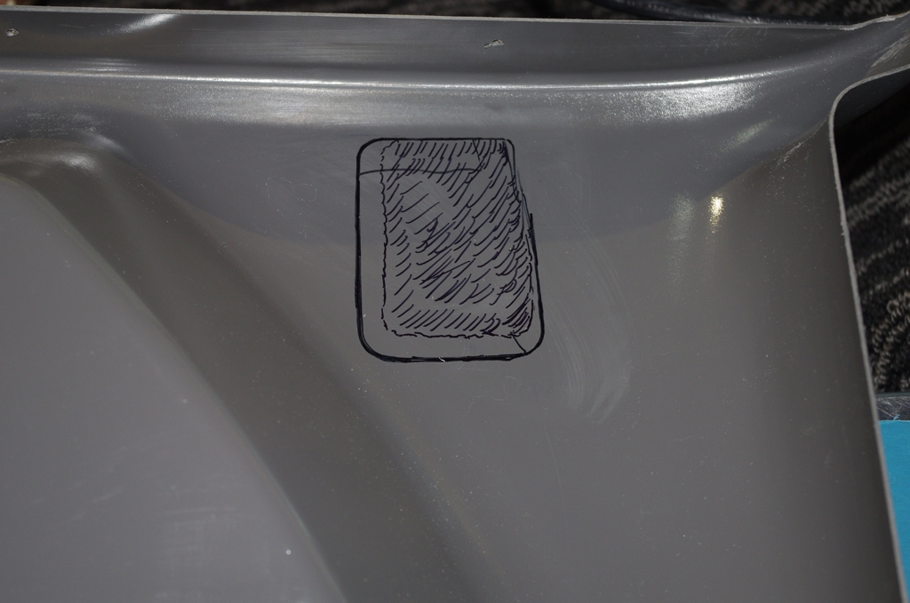
 

Instrument Panel (5)

With the fuselage now initially primed, the installation of the instrument panel could begin.  As many connections as possible were first completed before insertion of the panel.

PREPARATIONS

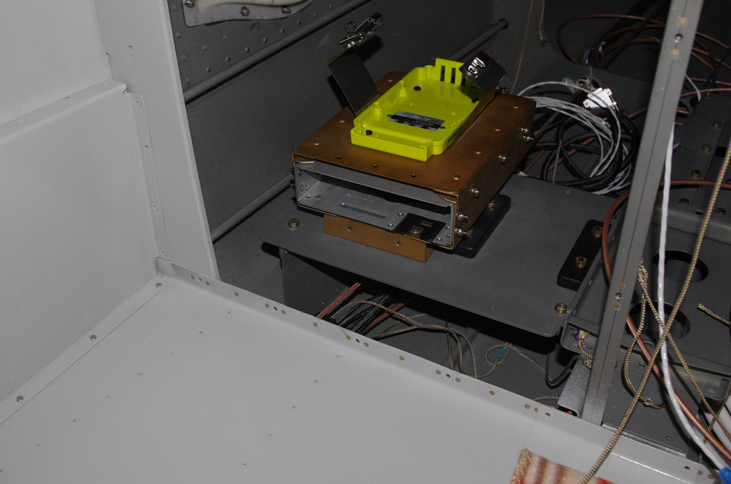
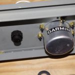
Here the GTX45R remote transponder / ELT brackets were installed behind the baggage bulkhead.  Termination of the major NAV/COM antennas with BNC or TNC connections behind the front sub-panel was also done.


ANL fuse and ammeter shunts were installed on the firewall side by Rich. The remote Airwolf oil filter bracket was bolted into place.  Inside, the forward cabin heating tube was attached in the center tunnel.  Many other items were added to the cockpit-side of the firewall – cross-tie contactor, ground blocks, GAD29 ARINC adapter, GEA24 engine monitor…


Initial wiring for B+C LR3C voltage regulators, VPX-PRO electronic circuit breakers, Guardian CO detector, floor lights, panel fans, etc. all were set to final configuration where possible.  The instrument panel was repacked in the original shipping crate for migration from my basement to the workshop for installation.


INSTALL

Rich and Tal unbox the instrument panel from the shipping crate, then hand to me for positioning under the dashboard.  Notice the PFD and MFD were removed to save weigh and allow easier access during installation.


Job done on the basic installation.  I had expected a tougher battle getting everything aligned, but was pleasantly surprised how well the panel fit on the first try.  In retrospect this was probably due to the time/effort/diligence applied to the mock-up and bench testing previous done in the basement workshop.


FURTHER CONFIGURATION AND INITIAL TESTING

With the panel now fastened in place, final attachment of wire bundles to VPX-Pro, voltage regulators, avionic stack, ground blocks, fuse holder… could occur.


Here was the first power-on testing performed with the panel inside the fuselage. Checks on basic functions were good, but a few tweeks were needed for control stick inputs, autopilot servos and trim motors.  All of these turned out to be simple repositioning of DSUB connector pins.


The G3X configuration pages show most of the main equipment details in their responses to CANBUS signals.  A few items have not yet been connected, so further testing will be performed as these devices are brought online.


Thumbs up on the radio COM1 and COM2 checks!  Now on to pulling and terminating more wire through the side cable chases.


Prime/Paint (2)

Completion of body work and initial priming of the fuselage with DesoPrime CF took many weeks to accomplish.

The frame around the baggage door was just one example where the height difference between parts was leveled and smoothed.  After scuffing the raw aluminum surface and degreasing thoroughly, a mixture of West Marine resin/colloidal silica was applied to provide a hard substrate for later Superfil covering.  Multiple layers and many hours of sanding ensued to get the final result.


The treatment for just aluminum surfaces was scuff, degrease, apply Prekote, then prime.  The fuselage top was primed in a separate sequence than the bottom. (more on that later).


Before and after shots of the fuselage from the rear. The left photo shows filler transitions on the rear window, door openings, rear air scoop, and canopy/skin seams.


Before and after shot of the fuselage from the front.  The left photo shows body work around the windscreen base, door openings, forward air scoop and upper/side fuselage skin seams.


After the first prime on the upper fuselage, additional filler and smoothing was needed in a few places.  Particular improvements were applied for the windscreen base – where the transition to aluminum to the fiberglass base needed attention. The left photo shows the sanded elements ready for a second primer round.  The fuselage was then lifted about 6″ to provide more room to spray the bottom.


Having never painted upside-down before, applying primer to the bottom was a real challenge.  It took a few days of preparation before the painting session.  The results seemed fine, but later sanding will reveal whether the primer thickness is uniform across the surface.ad


MISCELLANEOUS

Custom elements were made prior to installation of the instrument panel and wiring harness.  The left photo shows 1/4″ connection tabs made into ground blocks for the wing roots and tail section.  The right photos shows brackets to hold cable bundles under the Aerosport kick panels near the rudder pedals.  These were needed as the default Vans brackets were too ‘proud’ (too high to fit under the plastic panels).


On the left is the SEM primed bracket with 2 AWG cables for PRI BATT and SEC BATT running from behind the baggage area to the firewall.  The kick panel was rough fit for the dummy instrument panel.  Later adjustments will be made when the real panel is installed.


Upper Fuselage (1)

Now that the instrument panel had passed basic bench testing, it was time to permanently attach to the fuselage and firewall.

The metal surfaces were treated with SEM Self-etch primer.


The fiberglass reinforcement plate prepared in previous posts was then added to help strengthen the grips.


The underside portion of the dashboard was painted in the standard interior 707 Boeing grey color.


Here the upper dashboard / glare shield area is taped and prepared for painting.  While the intention is to later cover with some fabric material, the flat black base coat could be used AS-IS in the meantime.


Now that the upper dashboard was ready, the firewall was prepared for final attachment.  Here a 4-mil acrylic sheet is taped to the firewall.  Holes were traced using a blue Sharpie pen.  The acrylic template was used for precisely cutting LavaShield insulation material. (more on that in a later post.)


The oil cooler bracket was riveted together and nutplates applied.  The completed unit was then riveted onto the firewall with AN470AD4-4 rivets.


The main wiring pass-through in the upper center of the firewall is 1″ diameter stainless steel.  The photos show from the firewall side and the cockpit side. This location will contain most of the general sensor wires (fuel pressure, oil pressure, oil temperature, tachometer,…), plus starter contactor, Surefly and Slick ignitions, and voltage regulator connections.


The smaller 3/4″ pass-through on the far right side will house the CHT and EGT sensor wires.


Here the upper fuselage / dashboard unit is clecoed onto the main fuselage.


The longitudinal ribs were connected to the firewall with CherryMax CR3212-4-2 rivets. Using structurally rated pull rivets was much easier to install than bucking, plus just as strong.


Next were the cowl attach hinges.  These were prepared earlier, now just held in place with clecoes and spring clamps. The alligator jaw, dual piston pneumatic squeezer was perfect for rivet installation.


Cowl hinge results shown from top and bottom turned out very well.


The technique used to rivet the side seams was different from previous work on the fuselage. In this case a large, heavy bucking bar was held on the outside and the shop heads were back driven from the inside. This approach helped smooth the seams, plus reduced the shallow skin cupping seen on earlier efforts.


The upper forward fuselage interior is now ready for installation of the instrument panel. However, there are some further fuselage activities to be performed prior to then.